1
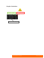
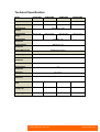
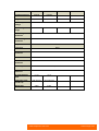
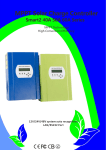
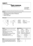
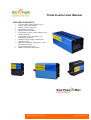
Theta Inverter User Manual FEATURES & BENEFITS True sine wave output (THD 5% Typ.) Input & output fully isolated Thermo control cooling fan High efficiency inverter Advanced microprocessor Input polarity reverse / under voltage / over voltage protection Output short circuit / overload / over temperature protection Capable of driving highly reactive and capacitive loads LED Color indicators display input, output level & failure status CE and ROSH Approved Quality construction & durability www.solarpower-mart.com www.scorigin.com Introduction Your new Theta power inverter is a member of the most advanced line of DC to AC inverters available today. It will give you years of dependable service in your vehicle, boat, RV, or remote home. To get the most out of your Theta inverter, it must be installed and used properly. Please read the installation and operating instructions in this manual carefully before installing and using your Theta Inverter. Pay special attention to the CAUTION and WARNING statements in this manual and on the Theta Inverter. CAUTION statements identify conditions or practices which could result in damage to your Theta inverter or to other equipment. WARNING statements identify conditions or practices that could result in personal injury or loss of life. CAUTION WARNING How Your Theta Works An inverter is an electronic device that converts low voltage DC (direct current) electricity from a battery or other power source to the standard 240 volts AC (alternating current) household power. In designing the Theta, SC Origin has used design techniques previously employed in computer power supplies to give you an inverter that is smaller, lighter, and easier to use than any other inverter with a similar power rating. Principle of operation The Theta converts power in two stages. The first stage is a DC-to-DC converter that raises the low voltage DC at the inverter input to 240 volts DC. The second stage is the actual inverter stage. It converts the high voltage DC into 240 volts, 60 Hz or 50 Hz AC. The DC-to-DC converter stage uses modern high frequency power conversion techniques that makes the bulky transformers found in inverters based on older technology obsolete. The inverter stage uses advanced power MOSFET transistors in a full bridge configuration. This gives you excellent overload capability and the ability to operate tough reactive loads like lamp ballasts and small induction motors. Theta Modified Sine Wave output waveform The AC output waveform of the Theta is called a “quasi-sine wave”or a “modified sine wave. ”It is a stepped waveform that is designed to have characteristics similar to the 3 sine wave shape of utility power. A waveform of this type is suitable for most AC loads, including linear and switching power supplies used in electronic equipment, transformers, and motors. This waveform is much superior to the square wave produced by many other DC to AC inverters. The modified sine wave produced by the Theta is designed to have a RMS (root mean square) voltage of 240 volts, the same as standard household power. Most AC voltmeters (both digital and analog) are sensitive to the average value of the waveform rather than the RMS value. They are calibrated for RMS voltage under the assumption that the waveform measured will be a pure sine wave. These meters will not read the RMS voltage of a modified sine wave correctly. They will read about 2 to 20 volts low (i.e. about 230V) when measuring the output of the Theta. For accurate measurement of the output voltage of the Theta, a true RMS reading voltmeter such as a Fluke 87, Fluke 8060A, Beckman 4410, or Triplett 4200 must be used. www.solarpower-mart.com www.scorigin.com Installation Power source For optimum performance, the power source must provide between 11 and 14.5 volts (22-30 volts for Theta 24V input system) and must be able to supply sufficient current to operate the load. The power source may be a battery or a well regulated DC power supply. As a rough guideline, divide the power consumption of the load (in watts) by 10 (by 20 for Theta 24V input system) to obtain the current (in amperes) the power source will deliver. Example: Load is rated at 120 watts. Power source will be able to deliver: 120 ÷ 10 = 12 amps (or 6 amps for Theta 24V input system) CAUTION: The Theta must be connected only to batteries with a nominal output voltage of 12 volts (24 volts for Theta 24V input system). The Theta will not operate from a 6 volt battery and will be damaged if connected to a voltage source above 16 volts. WARNING: RISK OF EXPLOSIVE GASES Sparks may occur when connecting the inverter to the battery. These sparks can ignite accumulated battery gases and cause an EXPLOSION. VENTILATE BATTERY IMMEDIATELY BEFORE CONNECTING BATTERY TO INVERTER. For temporary connections a) Connect the inverter’ s positive DC wire/clip to the positive battery terminal. b) Connect the inverter’ s negative DC wire/clip to the free end of the cable (negative). When disconnecting the inverter, always do so in the reverse sequence of the connecting procedure and break the first connection as far away from the battery as possible. The purpose of this procedure is to eliminate the possibility of a spark from the battery when connecting and disconnecting, to avoid possible ignition of gases. Placement of inverter For best operating results, the inverter should be placed on a flat surface, such as the floor or seat of a vehicle. Approximately 0.6 m (2 feet) of cord has been provided for this purpose. The inverter should only be used in locations that meet the following requirements: a) Dry - do not allow water to drip or splash onto the Theta. b) Cool - ambient air temperature should be between 0º C and 40º C - ideally between 15º C and 25º C. Do not place the inverter on or near a heating vent or any piece of equipment which is generating heat above room temperature. Do not place the inverter in direct sunlight unnecessarily. c) Ventilated - allow at least one inch of clearance around the Theta for air flow. Do not place items on or over the inverter during operation. Make sure that air is allowed to circulate freely around the unit. A fan is helpful in the case where the inverter is operating at maximum power output for extended periods. The unit will shut down if the internal temperature exceeds 90ºC. It will restart once it cools off. CAUTION: THETA CASE GETS HOT The case of the Theta acts as a heat sink, dispersing internally generated heat. When the Theta is operating at high power levels (above 100 watts) for extended periods, the case will get hot. Surface temperatures may approach 60º C (140º F) on some parts of the case. When operating at high power levels, do not place the Theta on or near materials that may be affected by these temperatures. Use caution when handling the Theta if it is operating at high power levels. Safe - do not use the Theta near flammable materials or in any location which may accumulate flammable fumes or gases. www.solarpower-mart.com www.scorigin.com Rated versus actual current draw of equipment Manufacturers of electrical and electronic equipment often over rate the current drawn by their products. If a piece of electrical or electronic equipment is rated at 300 watts or less, the Theta 300W will probably operate it. The inverter has overload protection, so it is safe to try it with equipment rated at 300 watts or more. The inverter will shut down if it is overloaded, and will restart once the overload is removed. Safety instructions This equipment should be installed and serviced by a qualified electrician or professional that is familiar with the inverter functions and operations. Failure to do may result in injury or inverter damaged. 1. Do not connect the Theta inverter unit to AC distribution wiring, such as your house wiring. 2. Keep the Theta inverter unit away from water. Do not allow water to drip or splash onto the inverter. Do not insert or pull out plug with wet hands. 3. Keep the Theta inverter unit in cool environments. Ambient air temperature should be between 0º C and 40º C. Keep from direct sunlight and away from heating vents. 4. Keep the Theta inverter unit away from flammable material or in any. 5. With heavy usage, the Theta inverter unit will become warm and possibly hot. Keep it away from any heat sensitive materials. 6. Make sure the opening to the ventilation fan and vent holes are not blocked. 7. Do not open the Theta inverter unit because it is a high voltage device and can induce an electrical shock. It may result in injury or even death. 8. Use the proper size wiring provided. The Theta inverters can draw many amps from the DC source and can easily melt wires if not fused and sized properly. 9. Make sure to connect the Theta inverter with battery/batteries correctly. Reverse polarity connection may burn invert fuse. Immediate switch off the inverter and do not use the equipment. 10. When cleaning the Theta inverter, please switch off power (unplug the inverter). Carefully clean with dry cloth. Do not use wet cloth or cleanser. How to use the Theta Inverter 1. Power supply selection - It must get power from storage battery/batteries or a car cigarette lighter port. Input voltage can be 12Vor 24V or 48V depending on the model. 1. Connect Theta inverter to power supply.Set the switches into the OFF position(including inverter and appliances). 2. Get power from battery/batteries: Connect the black U shape end of battery cable with the Black connecting pole(-) of inverter and the red U shape end with the red connecting pole (+). 3. Get power from car cigarette lighter port, insert the car cigarette lighter plug into the car cigarette lighter port. 4. Connect inverter to appliances. Make sure the load power within the rated power of inverter and the start power should not exceed the peak power of the inverter. When having the inverter connected with appliances and a power supply, switch on the inverter and appliances. Input low voltage protection A: When battery voltage is low, a buzzer will alarm, which indicates DC power supply voltage is descending and batteries need to recharge. B: When input voltage is below 10V 0.5V(for 12V input inverter)/20V 1.0V(for 24V input inverter), AC output will be automatically shut off, a buzzer alarm and ALARM/WARNING light turns red at the same time. www.solarpower-mart.com www.scorigin.com Input over voltage protection When input voltage reach 15V 0.5V (for 12V input inverter)/30V 1.0V (for 24V input inverter), ALARM/WARNING light turns red and the AC output will be shut off automatically. Short circuit protection When short circuits occur, output will be shut off and ALARM/WARNING light turns red. Overload protection When overloads occur, output will be shut off and ALARM/WARNING light turns red. Reverse polarity input protection When battery terminals are reverse connected, fuse will be burned to protect appliances. Invert thermal protection When inner temperature exceeds 70ºC, AC output will ALARM/WARNING light turns red. It is unusable for 15 minutes. automatically shut off, Charge thermal protection When radiator temperature exceeds 50ºC, the inner cooling fan will automatically turn on to cool the inverter. www.solarpower-mart.com www.scorigin.com TROUBLESHOOT & SOLUTION Acoustics buzzer alarms When applying the inverter to acoustics devices, some inferior acoustics devices will buzz, this is because the output wave from the inverter is a modified sine wave. TV Interference You can get minimum interference through use of a filter. On some occasions, when the interference of very weak signals becomes too obvious, you can try the following: Place the inverter far from the TV and TV antenna. Try to change the direction of TV signal cable and TV antenna to reduce the interference to minimum, Use screen cable antenna of high quality. Unresponsive Inverter 1. Poor connection between batteries & inverter, reconnect them. 2. Reverse polarity connection and fuse burned out, replace the fuse with a same spec fuse and reconnect. Output voltage very low 1. Overload. Load power exceeds rated power, shut off part of the appliances and restart inverter. 2. Input voltage too low. Make sure input voltage is within the rated range. Low-voltage alarm 1. Battery has no power. Recharge the battery via charger or solar. 2. Battery voltage too low or in poor connection. Recharge the batteries, check terminal connection or clean terminals with a dry cloth. Inverter no output 1. Battery voltage too low, recharge or replace the batteries. 2. Load power too high, shut off some of the appliances and restart inverter. 3. Inverter thermal protection. Cool the inverter and place it in an area with good ventilation. 4. Inverter start-up fails. Restart the inverter. 5. Reverse polarity connection and fuse burned out, replace the fuse with a same spec fuse and reconnect. Inverter does not work Check the power switch, fuse and battery connecting cables or car cigarette lighter port. Indicator light on AC side: WORK/WORKING: When inverter is working, this light turns on. ALARM/WARNING: When low voltage, over voltage, short circuit, overload, or thermal protection occur, this light turns on. www.solarpower-mart.com www.scorigin.com Graphic illustration On LED - Green Alarm LED - Red Universal Power Socket www.solarpower-mart.com www.scorigin.com Technical Specification Model SPM150MS SPM300MS SPM500MS SPM1000MS Continuous Power 150W 300W 500W 1,000W Surge Power 300W 600W 1,000W 2,000W Rated Output Voltage VAC 240V +/-10% Input Voltage Range DC11V-15V DC11V-15V DC11V-15V Over Voltage Shutdown Over DC 15V Under Voltage Shutdown Below DC 11V Output Wave Form DC11V-15V Modified Sine Wave Frequency 60Hz Over Load Shutdown Yes Thermal Shutdown Yes Short Circuit Shutdown Yes Efficiency Up to 90% Total Harmonic Distortion <5% No Load Current Draw <0.3A <0.3A <0.4A <0.6A Dimension (mm) (L x W x H) 105*55*120 105*55*120 105*55*150 105*70*210 0.6kg 0.7kg 0.8kg 1.8kg Weight (kg) www.solarpower-mart.com www.scorigin.com Model SPM2000MS SPM3000MS Continuous Power 2,000W 3,000W Surge Power 4,000W 6,000W Rated Output Voltage VAC 240V +/-10% Input Voltage Range DC22V-30V DC22-30V Over Voltage Shutdown Over DC 30V Under Voltage Shutdown Below DC 22V Output Wave Form Modified Sine Wave Frequency 60Hz Over Load Shutdown Yes Thermal Shutdown Yes Short Circuit Shutdown Yes Efficiency Up to 90% Total Harmonic Distortion <5% No Load Current Draw <0.6A <0.6A Dimension (mm) (L x W x H) 310*150*70 340*150*152 2.7kg 3.3kg Weight (kg) www.solarpower-mart.com www.scorigin.com Model SPM300PS SPM500PS SPM1000PS Continuous Power 300W 500W 1,000W Surge Power 600W 1,000W 2,000W Rated Output Voltage VAC 240V +/-10% Input Voltage Range DC11V-15V DC11V-15V DC11V-15V Over Voltage Shutdown Over DC 15V Under Voltage Shutdown Below DC 11V Output Wave Form Pure Sine Wave Frequency 60Hz Over Load Shutdown Yes Thermal Shutdown Yes Short Circuit Shutdown Yes Efficiency Up to 90% Total Harmonic Distortion <5% No Load Current Draw <0.6A <0.6A <0.8A Dimension (mm) (L x W x H) 150*130*52 210*150*70 310*150*70 0.9kg 1.5kg 2.6kg Weight (kg) www.solarpower-mart.com www.scorigin.com Model SPM2000PS SPM3000PS Continuous Power 2,000W 3,000W Surge Power 4,000W 6,000W Rated Output Voltage VAC 240V +/-10% Input Voltage Range DC22V-30V DC22V-30V DC22V-30V Over Voltage Shutdown Over DC 30V Under Voltage Shutdown Below DC 22V Output Wave Form Pure Sine Wave Frequency 60Hz Over Load Shutdown Yes Thermal Shutdown Yes Short Circuit Shutdown Yes Efficiency Up to 90% Total Harmonic Distortion <5% No Load Current Draw <0.1A <0.1A Dimension (mm) (L x W x H) 395*150*70 370*150*152 3.2kg 4.2kg Weight (kg) www.solarpower-mart.com www.scorigin.com SC ORIGIN LIMITED PRODUCT WARRANTY SC Origin manufactures its hardware products from parts and components that are new or equivalent to new in accordance with industry-standard practices. SC Origin warrants the Theta to be free from defects in workmanship or materials for 12 months from the date of purchase. During this period, SC Origin will, at its option, repair or replace the defective product free of charge. This warranty will be considered void if the unit has suffered any physical damage or alteration, either internally or externally, and does not cover damage arising from improper use, attempting to operate products with excessive power consumption requirements, or from use in an unsuitable environment. This warranty will not apply where the product has been misused, neglected, improperly installed, or repaired by anyone other than SC Origin. In order to qualify for the warranty, the product must not be disassembled or modified without prior authorization by SC Origin. Repair or replacement are your sole remedies and SC Origin shall not be liable for damages, whether direct, incidental, special, or consequential, if caused by negligence or fault. SC Origin owns all parts removed from repaired products. SC Origin uses new and reconditioned parts made by various manufacturers in performing warranty repairs and building replacement products. If SC Origin repairs or replaces a product, its warranty term is not extended. THIS IS A SC ORIGIN ONLY WARRANTY, AND THE COMPANY MAKES NO WARRANTIES, EXPRESS OR IMPLIED, INCLUDING WARRANTIES OF MERCHANTABILITY AND FITNESS FOR A PARTICULAR PURPOSE. LIMITED LIABILITY The Limited Warranty set forth herein are expressly in lieu of and exclude all other expressed or implied warranties, including but not limited to warranties of merchantability and of fitness for particular purpose, use, or application, and all other obligations or liabilities on the part of SC Origin, unless such other warranties, obligations or liabilities are expressly agreed to in writing signed and approved by SC Origin. SC Origin shall have no responsibility or liability whatsoever for damage or injury to persons or property, or for other loss or injury resulting from any cause whatsoever arising out of or related to misuse or installation of the inverters. Under no circumstances shall SC Origin be liable for incidental, consequential or special damages, howsoever caused. Loss of use, loss of profits, loss of production and loss of revenues are therefore specifically excluded. Send product purchased in Pan Asia to: SC Origin (M) Sdn Bhd No. 87, Jalan TPP 1/13 Taman Industri Puchong 47100 Puchong Selangor THE LIMITED WARRANTY IS THE ONLY WARRANTY OF SC ORIGIN (M) SDN BHD. THERE ARE NO OTHER WARRANTIES, EXPRESSED OR IMPLIED, EXCEPT AS PROVIDED BY LAW, INCLUDING THE IMPLIED WARRANTY OF QUALITY, MERCHANTABILITY OR FITNESS FOR A PARTICULAR PURPOSE AND SUCH IMPLIED WARRANTIES, IF ANY, ARE LIMITED IN DURATION TO THE TERM OF THE LIMITED WARRANTY. Think before you print! www.solarpower-mart.com www.scorigin.com