1
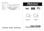
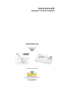
CA-32 & CA-32F
Colormix™ & Foot Controller
USER MANUAL
Both items sold individually!
Chauvet, 3000 N 29th Ct, Hollywood, FL 33020 U.S.A
(800) 762-1084 – (954) 929-1115
FAX (954) 929-5560
www.chauvetlighting.com
TABLE OF CONTENT
BEFORE YOU BEGIN........................................................................................................................................................... 3
WHAT IS INCLUDED ................................................................................................................................................................................ 3
UNPACKING INSTRUCTIONS .................................................................................................................................................................... 3
SAFETY INSTRUCTIONS .......................................................................................................................................................................... 3
INTRODUCTION ................................................................................................................................................................... 4
FEATURES ............................................................................................................................................................................................ 4
PRODUCT OVERVIEW (CA-32F)............................................................................................................................................................. 4
PRODUCT OVERVIEW (CA-32) ............................................................................................................................................................... 5
SETUP ................................................................................................................................................................................... 6
CONNECTION ........................................................................................................................................................................................ 6
CA32 Colormix™ Controller.......................................................................................................................................... 6
CA32F Colormix™ Foot Controller ............................................................................................................................... 6
OPERATING FUNCTIONS......................................................................................................................................................................... 7
CA32 Colormix™ Controller.......................................................................................................................................... 7
Master Slider ...................................................................................................................................................................................................... 7
Hold .................................................................................................................................................................................................................... 7
Spectrum Mix...................................................................................................................................................................................................... 7
Chase ................................................................................................................................................................................................................. 7
Sound ................................................................................................................................................................................................................. 7
Full On ................................................................................................................................................................................................................ 7
Blackout.............................................................................................................................................................................................................. 7
CA32F COLORMIX™ FOOT CONTROLLER MODES ................................................................................................................................... 8
Chase Mode ....................................................................................................................................................................................................... 8
Hold Color Mode................................................................................................................................................................................................. 8
Full On ................................................................................................................................................................................................................ 8
Blackout.............................................................................................................................................................................................................. 8
APPENDIX............................................................................................................................................................................. 9
DMX PRIMER ....................................................................................................................................................................................... 9
Fixture Linking .................................................................................................................................................................................................... 9
MAINTENANCE .................................................................................................................................................................................... 10
RETURNS PROCEDURE ........................................................................................................................................................................ 10
CLAIMS .............................................................................................................................................................................................. 10
GENERAL TROUBLESHOOTING .............................................................................................................................................................. 11
TECHNICAL SPECIFICATIONS ................................................................................................................................................................ 12
CA32 & CA32F User Manual
2
Revision: 2004-11-03/15:00
BEFORE YOU BEGIN
What is included
This manual includes instructions for both the CA-32 and CA-32F controllers.
CA-32 Colormix™
¾ 1 x CA-32
¾ DC 9V power adapter
¾ Warranty Card & Manual
CA-32F Colormix™ Foot Controller
¾ 1 x CA-32F Foot Controller
¾ 10m/32.8ft 5-pin XLR cable
¾ Warranty Card & Manual
Unpacking Instructions
Immediately upon receiving a fixture, carefully unpack the carton, check the contents to ensure that
all parts are present, and have been received in good condition. Notify the shipper immediately and
retain packing material for inspection if any parts appear damaged from shipping or the carton itself
shows signs of mishandling. Save the carton and all packing materials. In the event that a fixture
must be returned to the factory, it is important that the fixture be returned in the original factory box
and packing.
Safety Instructions
Please read these instructions carefully, which includes important
information about the installation, usage and maintenance?
•
•
•
•
•
•
•
•
•
•
Caution!
Please keep this User Guide for future consultation. If you sell the unit to another user, be sure that
they also receive this instruction booklet.
Always make sure that you are connecting to the proper voltage and that the line voltage you are
connecting to is not higher than that stated on decal or rear panel of the fixture.
This product is intended for indoor use only!
To prevent risk of fire or shock, do not expose fixture to rain or moisture. Make sure there are no
flammable materials close to the unit while operating.
The unit must be installed in a location with adequate ventilation, at least 50cm from adjacent
surfaces. Be sure that no ventilation slots are blocked.
Always disconnect from power source before servicing or replacing lamp or fuse and be sure to
replace with same lamp source.
In the event of serious operating problem, stop using the unit immediately. Never try to repair the unit
by yourself. Repairs carried out by unskilled people can lead to damage or malfunction. Please
contact the nearest authorized technical assistance center. Always use the same type spare parts.
Don’t connect the device to a dimmer pack.
Make sure power cord is never crimped or damaged.
Never disconnect power cord by pulling or tugging on the cord.
There are no user serviceable parts inside the unit. Do not open the housing or attempt
any repairs yourself. In the unlikely event your unit may require service, please contact
CHAUVET.
CA32 & CA32F User Manual
3
Revision: 2004-11-03/15:00
INTRODUCTION
Features
CA-32 Colormix™ Controller
•
•
•
•
•
•
•
•
•
9 different hold-color buttons for immediate color access
fader access to 32 predefined mixed colors
fade time control
12 different chase patterns to choose from
chase speed control
master dimmer level
blackout button
full on button
sound button
CA-32F Colormix™ Foot Controller
•
•
•
•
•
powered by CA-32 controller
10m/32.8ft 5-pin XLR cable
rugged pedal buttons
access to Down, Up, Full On and Mode functions
works exclusively with CA-32 Colormix™ Controller
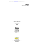
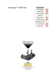
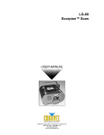
Product Overview (CA-32F)
Operating Modes
> Blackout (LED On)
> Hold Color (LED Off)
> Chase (LED Blinking)
Down
Up
Full On
Mode
Pedal
Function
Down
Toggles hold colors or chase patterns
Up
Toggles hold colors or chase patterns
Full On
Turns all lamps to full output
Mode
Selects operating modes, blackout, hold-color
& chase
CA32 & CA32F User Manual
4
Revision: 2004-11-03/15:00
Introduction
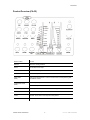
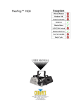
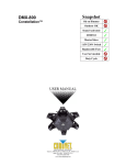
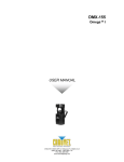
Product Overview (CA-32)
Button or Fader
Function
Blackout
Blackout for all Stage Washes
Full On
Turn all lamps to full output
Sound
Activates Sound to Light Mode
Master
Overall Intensity
Speed-Fade
(fader)
Chase speed adjust between .1 and 2.5 seconds while conversely affecting fade
time between chases.
Chase/Spectrum Mix
(fader)
Select from preset pattern chases
Select from 32 predefined colors
Hold Colors
9 buttons provide immediate activation of the most popular colors available
Hold
Activates “Hold Colors” palette
Chase
Activates “Chase” fader control of preset chase patterns
Spectrum Mix
Activates “Spectrum Mix” fader for control of 32 predefined colors
CA32 & CA32F User Manual
5
Revision: 2004-11-03/15:00
SETUP
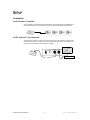
Connection
CA32 Colormix™ Controller
Using a qualified 3-pin XLR DMX cable as described in the Appendix section under DMX Primer,
connect the output of the CA-32 Controller to the input of the first TFX-900 Stage Wash 900.
CA32F Colormix™ Foot Controller
The CA32F foot controller connects to the CA32 using the 5-pin XLR cable foot controller output,
located at the rear of the controller. This cable is included with your purchase of the CA32F. The
CA32F will only work with the CA32 Colormix™ Controller.
To Fixtures
CA32 & CA32F User Manual
6
Revision: 2004-11-03/15:00
Operating Functions
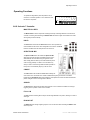
Operating Functions
6
256
5
64
4
128
3
32
2
8
4
1
16
2
be set to the off position.
1
Colormix™ Controller, dipswitch # 10 on all fixtures must
OPTION
To operate the Stage Wash (TFX-900) with the CA-32
7
8
9 10
OFF
ON
CA32 Colormix™ Controller
M AST ER SL ID ER
The Master Slider is used to adjust the overall light intensity of all Stage Washes connected to the
controller. Increasing and decreasing the Master Slider will result in slight color deviation from what
was originally set at full intensity.
HOLD
The Hold button will activate the Hold Color function which provides the
user immediate access to the colors designated on the buttons. The Hold
button is activated when the LED just above it is turned on.
SPECTRUM MIX
The Spectrum Mix button will activate the Spectrum Mix
slider which provides the user immediate access to 32 predefined/mixed colors as listed along the right side of the
slider. Simply slide the slider up and watch tentatively as the
colors change gradually. It is best to move the slider very
slowly in order to achieve the greatest resolution possible so
that you don’t unintentionally skip any of the 32 colors.
CHA SE
The Chase button will activate the Chase slider enabling the
user to select from 12 defined color chases as labeled directly along the left side of the slider.
Positioning the Speed/Fade slider will increase the chase speed and shorten the fade time between
pattern changes or do the exact opposite as labeled.
SOUND
The Sound button will activate the internal microphone on the controller and enable sound to light
triggering of the 12 pattern chases in the controller.
FU LL ON
The Full On button will bring all the lamps in all the Stage Washes to full power, resulting in a wash of
white light.
BLACKOUT
The Blackout button brings all lighting output to 0 or off. The same affect as sliding the Master slider
all the way down.
CA32 & CA32F User Manual
7
Revision: 2004-11-03/15:00
Operating Functions
CA32F Colormix™ Foot Controller Modes
The CA32F was created specifically to work with the CA32 Colormix™ Controller. No other device
should be connected to its 5-pin XLR connector.
Turning on the power button on the CA32F will disable the CA32 Colormix™ Controller. This is
normal operation. To regain control using the CA32 Controller simply turn off the CA32F.
CHA SE MOD E
To enable the Chase mode, press the {Mode}
pedal and hold until the LED blinks. The Up and
Down pedals allows the user to select any of the
12 chase patterns available.
HOLD COLOR MOD E
To enable the Hold Color Mode, press the
{Mode} pedal until the LED is off. The Up and
Down pedals allows the user to select any of the 9 preset primary colors available.
FU LL ON
The Full On pedal will bring all the lamps in all the Stage Washes to full power, resulting in a wash of
white light.
BLACKOUT
To enable the Blackout Mode, press the {Mode} pedal until the LED is on. All light output will be
brought to 0 or off.
CA32 & CA32F User Manual
8
Revision: 2004-11-03/15:00
APPENDIX
DMX Primer
There are 512 channels in a DMX-512 connection. Channels may be assigned in any manner. A
fixture capable of receiving DMX 512 will require one or a number of sequential channels. The user
must assign a starting address on the fixture that indicates the first channel reserved in the controller.
There are many different types of DMX controllable fixtures and they all may vary in the total number
of channels required. Choosing a start address should be planned in advance. Channels should
never overlap. If they do, this will result in erratic operation of the fixtures whose starting address is
set incorrectly. You can however, control multiple fixtures of the same type using the same starting
address as long as the intended result is that of unison movement or operation. In other words, the
fixtures will be slaved together and all respond exactly the same.
DMX fixtures are designed to receive data through a serial Daisy Chain. A Daisy Chain connection is
where the DATA OUT of one fixture connects to the DATA IN of the next fixture. The order in which
the fixtures are connected is not important and has no effect on how a controller communicates to
each fixture. Use an order that provides for the easiest and most direct cabling. Connect fixtures
using shielded two conductor twisted pair cable with three pin XLR male to female connectors. The
shield connection is pin 1, while pin 2 is Data Negative (S-) and pin 3 is Data positive (S+). CHAUVET
carries 3-pin XLR DMX compliant cables, DMX-10 (33’), DMX-4.5 (15’) and DMX-1.5 (5’)
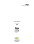
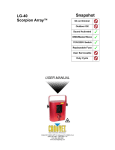
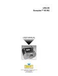
F I X T URE L I NKING
Figure 1 - DMX connector configuration
1
3
2
COMMON
INPUT
Note!
1
3
2
1
3
2
DMX +
Resistance 120
ohm 1/4w between
pin 2 (DMX -) and
pin 3 (DMX +) of
the last fixture.
OUTPUT
DMX -
Termination reduces signal errors and to
avoid signal transmission problems and
interference, it is always advisable to connect
a DMX signal terminator.
If you use a controller with a 5 pin DMX output connector, you will need to use a 5
pin to 3 pin adapter. CHAUVET Model No: DMX5M.
The chart below details a proper cable conversion:
3 Pin to 5 Pin Conversion Chart
Conductor
3 Pin Female (output)
5 Pin Male (Input)
Ground/Shield
Pin 1
Pin 1
Data ( - )signal
Pin 2
Pin 2
Data ( + ) signal
Pin 3
Pin 3
Do not use
Do not use
Do not use
Do not use
CA32 & CA32F User Manual
9
Revision: 2004-11-03/15:00
Appendix
Maintenance
To maintain optimum performance and minimize wear fixtures should be cleaned frequently. Usage
and environment are contributing factors in determining frequency. As a general rule, fixtures should
be cleaned at least twice a month. Be sure to power off fixture before conducting maintenance.
Unplug fixture from power. Use a vacuum or air compressor and a soft brush to remove dust
collected on external vents and internal components. Clean all glass when the fixture is cold with a
mild solution of glass cleaner or Isopropyl Alcohol and a soft lint free cotton cloth or lens tissue. Apply
solution to the cloth or tissue and drag dirt and grime to the outside of the lens. Gently polish optical
surfaces until they are free of haze and lint.
Returns Procedure
Returned merchandise must be sent prepaid and in the original packing, call tags will not be issued.
Package must be clearly labeled with a Return Merchandise Authorization Number (RA #). Products
returned without an RA # will be refused. Call CHAUVET and request RA # prior to shipping the
fixture. Be prepared to provide the model number, serial number and a brief description of the cause
for the return. Be sure to properly pack fixture, any shipping damage resulting from inadequate
packaging is the customer’s responsibility. CHAUVET reserves the right to use its own discretion to
repair or replace product(s). As a suggestion, proper UPS packing or double-boxing is always a safe
method to use.
Claims
Damage incurred in shipping is the responsibility of the shipper; therefore the damage must be
reported to the carrier upon receipt of merchandise. It is the customer's responsibility to notify and
submit claims with the shipper in the event that a fixture is damaged due to shipping. Any other claim
for items such as missing component/part, damage not related to shipping, and concealed damage,
must be made within seven (7) days of receiving merchandise.
CA32 & CA32F User Manual
10
Revision: 2004-11-03/15:00
Appendix
General Troubleshooting
Applies to
Symptom
Solution(s)
Lights
Auto shut off
Check fan thermal switch reset
9
Beam is very dim or not
bright
Clean optical system or replace lamp
Breaker/Fuse keeps
blowing
Check total load placed on device
Chase is too slow
Check users manual for speed adjustment
Device has no power
Check for power on Mains.
Foggers
& Snow
Controllers
Dimmers
& Chaser
9
Check 220/110v switch for proper setting
9
9
9
9
9
9
9
9
9
9
9
Check device’s fuse. (internal and/or external)
Fixture is not
responding
Check DMX Dip switch settings for correct addressing
Check DMX cables
Check polarity switch settings
Fixture is on but there
is no movement to the
audio
Make sure you have the correct audio mode on the control
switches. If audio provided via ¼” jack, make sure a live
audio signal exists
9
9
Adjust sound sensitivity knob
Lamps cuts off
sporadically
Possible bad lamp or fixture is overheating.
Light will not come on
after power failure
Some discharge lamps require a cooling off period before
the electronics in the fixture can kick start it again, wait 5 to
10 minutes before powering up
Loss of signal
Use only DMX cables
9
Lamp may be at end of its life.
9
Install terminator
Note: Keep DMX cables separated from power cables or
black lights.
9
Moves slow
Check 220/110v switch for proper setting
9
No flash
Re-install bulb, may have shifted in shipping
9
No laser output
Bounce mirror motor may have shifted during shipping,
readjust
9
No light output
Check slip ring & brushes for contact
9
9
Install bulb
Call service technician
Relay will not work
Check reset switch
9
Check cable connections
Remote does not work
Make sure connector is firmly connected to device
9
Stand alone mode
All Chauvet lighting fixtures featuring stand-alone functions
do not require additional settings, simply power the fixture
and it will automatically enter into this mode
9
CA32 & CA32F User Manual
11
9
Revision: 2004-11-03/15:00
Appendix
Technical Specifications
WEIGHT & DIMENSIONS (CA32 COLORMIX™ CONTROLLER)
Length............................................................................................................................. 210 mm (8.3 in)
Width .............................................................................................................................. 140 mm (5.5 in)
Height ............................................................................................................................. 46 mm (1.81 in)
Weight ........................................................................................................................ .0.93 Kg (2.06 lbs)
WEIGHT & DIMENSIONS (CA32F FOOT CONTROLLER)
Length.............................................................................................................................. 305 mm (12 in)
Width ............................................................................................................................ 174 mm (6.85 in)
Height ............................................................................................................................. 44 mm (1.73 in)
Weight ......................................................................................................................... 1.27 Kg (2.82 lbs)
POWER
Operating Range ........................................................................................................DC 9V 300mA min
Adapter ...................................................................................................................................... Provided
THERMAL
Maximum ambient temperature............................................................................................ 40° (104° F)
CONTROL & PROGRAMMING
Data output ........................................................................................... locking 3-pin XLR female socket
Data pin configuration ..............................................................................pin 1 shield, pin 2 (-), pin 3 (+)
Protocols........................................................................................................................ DMX-512 USITT
ORDERING INFORMATION
Colormix™ Controller ......................................................................................................................CA32
Colormix™ Foot Controller ............................................................................................................CA32F
CA32 & CA32F User Manual
12
Revision: 2004-11-03/15:00