1
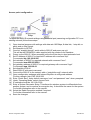
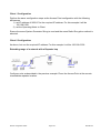
905U-E wireless Ethernet modem Configuration Guide
Introduction
The 905U-E Wireless Ethernet modem provides wireless communications between Ethernet
devices or Ethernet wired networks (LAN’s). It has an internal 900MHz spread spectrum
frequency hopping wireless transceiver, which can be used without a radio licence in many
countries
The 905U-E has a standard RJ45 Ethernet connection which will operate at up to 100Mbit
per sec. The module will transmit the Ethernet messages on the wireless band at up to
200Kbit per sec
To use the 905U-E modem with the DT8x range of data loggers, use the 905U-E modem as
an “Access Point” or “Client” modem.
Further information including the user's manual for the 905U-E radio modem can be found on
the Elpro website www.elprotech.com. Refer to the user's manual for more detailed
explanations of 905U-E commands and settings.
Access Point vs Client
The Access Point unit acts as the “wireless master” unit. The Access point sets up the
wireless links to the Client units, and controls the wireless communications.
An Access Point can connect to multiple Clients. In this example, the Access Point should be
the “central” unit.
905U-E Configuration Guide
Page 1 of 4
UM-0087-A0
An Access Point could be used as a “Repeater” unit to connect two 905U-E Clients which do
not have direct reliable radio paths.
Configuration Examples
To configure the 905U-E modem use the built-in web server.
To access the configuration make an Ethernet connection from your PC to the modem. There
are two methods of doing this.
1) Adjusting the PC
This requires the PC to be set to the same network as the default settings on the 905U-E,
using the 905U-E webpage. For further information refer to the manual.
2) Adjusting the 905U-E
This requires the 905U-E to be set on the same network as the PC, using a terminal
package such as DeTransfer or Hyperterminal.
As most installations will require the 905U-E modems to be connected to existing
networks, following are the details of how to configure the 905U-E modem using terminal
software.
NOTE: For your Gateway, Netmask and IP address settings, please consult your network
administrator.
905U-E Configuration Guide
Page 2 of 4
UM-0087-A0
Access point configuration
To adjust the 905U-E network settings using the serial port (assuming configuration PC is on
existing network) follow these steps
1)
2)
3)
4)
5)
6)
7)
8)
9)
10)
11)
12)
13)
14)
15)
16)
17)
Open terminal program with settings with data rate 19200bps, 8 data bits, 1 stop bit, no
parity and no flow control.
Set dipswitch to SETUP
Connect “straight through” serial cable to 905U-E and power up unit.
This will be the PROMOD-6 cable supplied with the modem from Datataker.
Power up the 905U-E. When prompted, strike the Enter key to abort automatic boot
Set IP address of 905U-E to required IP address with command “bip”.
For example bip 192.168.0.200
Set netmask of 905U-E to required netmask with command “bnm”.
For example bnm 255.255.255.0
Set gateway address of 905U-E to required gateway with command “bgw”.
For example bgw 192.168.0.1
Set dipswitch to RUN
Reset 905U-E with reset command.
Connect the 905U-E to the network with a “straight-through” network cable.
Open configuration webpage with Internet Explorer at configured address.
For this example: http://192.168.0.200/
Enter “Quick Start”, enter default username “user” and password “user” when prompted.
Under “Operating Mode” select Access Point.
IP address should be 192.168.0.200
Enter a System Generator String. This allows the wireless system to differentiate from
another system, and is used as an encryption key. It should be the same for the system.
For further information refer to the manual.
Select the Radio Encryption method if required.
For further information refer to the manual.
Save the changes.
905U-E Configuration Guide
Page 3 of 4
UM-0087-A0
Client 1 Configuration
Perform the same configuration steps as the Access Point configuration with the following
differences:
1) set IP address of 905U-E for the required IP address. For this example it will be
192.168.0.201
2) set the Operating Mode to Client
Ensure the same System Generator String is used and the same Radio Encryption method is
selected.
Client 2 Configuraiton
As above, but use the required IP address. For this example it will be 192.168.0.202
Extending range of a network with a Repeater hop
Configure units as described in the previous example. Place the Access Point at the remote
intermediate repeater location.
905U-E Configuration Guide
Page 4 of 4
UM-0087-A0