1
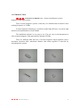
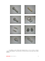
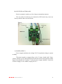
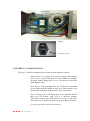
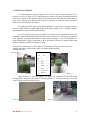
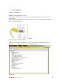
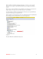
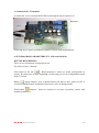
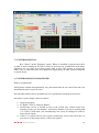
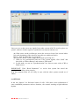
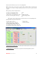
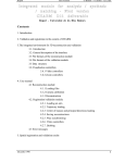
58Khz ACOUSTO MAGNETIC SYSTEMS WIRING HANDBOOK E.A.S. SISTEMAS ANTIHURTO, S.L. 1 Revisión 1 06/2012 1. INTRODUCTION. 2. SYSTEM DESCRIPTION. a. TRANSMITER ANTENNA TX. b. RECEIVER ANTENNA RX. c. POWER SUPPLY. 3. DIFFERENT CONFIGURATIONS. 4. ANTENNAS WIRING. 5. PC CONEXION. 1) Drivers installation. 2) Connexion Pc-Tx. 6. PARAMETERS SETTINGPROGRAMM. 1) Button description. 7. SYNCHRONIZATION. 8. OPTIONS. 9. COMMON PROBLEMS. 10. SAFETY RECOMMENDATIONS. E.A.S. SISTEMAS ANTIHURTO, S.L. 2 1. INTRODUCTION. E.A.S. SISTEMAS ANTIHURTO, S.L. design, manufacture acousto magnetic technology systems. These acousto magnetic systems, when they are installed and in function, their working frequence is 58 Khz. Acousto magnetic technology is typified to make high efficiency in system, high detection and small number of false alarms. The installation software is very easy to use. You can vary several parameters in order to match magnetic field generated by antennas 58 KHz. There are different kind and size of acousto magnetic alarm tag/labels with a maximum detection field (maximum distance that alarm tag/label is detected by acustomagnetic system). E.A.S. SISTEMAS ANTIHURTO, S.L. 3 According to space features that antennas have to cover we have to choose suitable alarm tag/label, so the patch has to be done between system and selected alarm tag/label. E.A.S. SISTEMAS ANTIHURTO, S.L. 4 2. SYSTEM DESCRIPTION. a. TRANSMITTER ANTENNA TX. Transmitter antenna is made up of 2 loops. Each loop is joined to an electronic transmitter board (photo 3), in the top connectors (X5) & (X6). TX Board Photo 3. X6 X5 CS1 CS2 Photo Monnoantena. ANTENNA LOOP MINI USB CONNECTOR PC + BUZZER - LED MASTER SLAVE CONNECTION E.A.S. SISTEMAS ANTIHURTO, S.L. POWER SUPPLY 5 B). RECIEVER ANTENNA RX. Receiver antenna is made up of two loops as transmitter antenna. The two ends of each loop are connected to RX board, they come one from up and the other one from down. Photo 6 Lower loop 1 A1 2 1 Upper loop 2 A2 RX Board S1 Buzzer/Light out X1 C) POWER SUPPLY. Power supply transforms net voltage 220 V in optimum voltage to system working. This power supply is composed by a coil of 1 Amp, a board with 3 fuses, electric current way in, with switch on/off with fuse-carrier and connector cables between board and coil. In photo 7 is shown power supply installed. Connexion of Power Supply is of 6 strands, keeping free nº 1. E.A.S. SISTEMAS ANTIHURTO, S.L. 6 Power Supply Photo 7 Interruptor on/off 3. DIFFERENT CONFIGURATIONS. There are 3 possible configurations to install acousto magnetic systems - Monoantenna. Is a system of an unique antenna. This antenna can be put in a side of the door or in the middle according to detection wished. Range door is even 1.20 metres by each side (with Hammer tag). - Dual System. In this configuration the TX board is assembled in one antenna and RX board in other one. Each antenna is put in each side of the door. Range door is even 2,50 meters. - Three antenna system. TX board goes in one antenna and the other two RX boards, each one in a different antenna. Transmitter antenna goes between the two leaves of the door and each receiver antenna in each side of door. Range big door. - For more types ask connections in factory. E.A.S. SISTEMAS ANTIHURTO, S.L. 7 4. ANTENNAS WIRING. In acustomagnetic system wiring, we need a less space to put antennas. If it’s possible we leave a space of 5-10 cm between the wall or exit door and outside limit of each one of antennas. We make the hole in the ground to fix each antenna on its ends. If there is pre-wiring each antenna will be put in each hole to coincide cable pass holes with holes of the bottom of antenna. It’s important observing around where antennas it’s going to be wired because if there is a bulb with neon lights (that works in frequency range of 50 - 60 KHz) or other acustomagnetic system wired in proximities. In case of being systems in proximities we only have to synchronize them (see parameter patch with program and synchronization), but in case of being near a bulb of neon light this can make interferences with system working. To solve the problem we must change bulbs of place (put them as far as possible of system) or replace them with another working in different frequency range. With the two antennas put in their places (TX antenna will be put nearer of power supply) and always one front the other, we make cable assembly: Configuration is: Power Supply P.S Photo 8 TX 1X 1 2 Blue 6 3 Grey 5 4 Black 4 5 6 Red 3 Yellow 2 White 1 7 Photo 9 Cable between 2 antennas (photo 10) has to be connected in the RX board through RJ45 connector and in the TX board (photo 11). Colours code have to be the same in both connexions (pin to pin). Photo 10 E.A.S. SISTEMAS ANTIHURTO, S.L. Photo 11 8 When we have assembled cables between antennas and cable of power supply to transmitter board, we can switch on power supply, to make this possible we press the switch on/off of one side of power supply TX board shows us if system is working properly. To obtain this well operation, leds line must be completely switched on (are located in the upper half part of the board). In the case this not happen, we must go changing jumpers position to get both led lines switch on. Jumpers Photo 13 When system is switched on right, we connect TX board with computer to match with the program. E.A.S. SISTEMAS ANTIHURTO, S.L. 9 5. PC CONEXION. 1) Drivers installation. Plugging in and turning on a device To install any USB device, just plug it in to your computer. Then, turn it on before connecting it. Next, decide which USB port to connect your device to. You can use any port the next time you plug in the device. Imagen 1. Plug the device into the USB port Windows can’t detect new hardware. You have to install it manually from control panelDevice manager_Other devicesUSB serial EAS Imagen 2. E.A.S. SISTEMAS ANTIHURTO, S.L. 10 Then appears the following message: How do you wish you to search driver software? Then you click on: “Search device software on the computer”. Imagen 3. Insert CD Then select folder: Drivers USB EAS The installation progress will be running. Imagen 4. E.A.S. SISTEMAS ANTIHURTO, S.L. 11 When installation in finished would appear this again: “Hardware can’t be found”. Thus you can see number 1 that USB Serial EAS has been recognized by Windows System. But the drivers of port COM haven’t been installed yet (see image 4) as you can see in image 4 number 2 in Other devices USB serial port it’s not installed If click Serial Port in USB Port with right button of the mouse you may install drivers from the CD following same steps than before. When installation is already finish you will see the USB Serial EAS in Control Panel Device Manager Port (COM & LPT) as seen in the image below. Imagen 5. Then the USB will be installed and ready to use. E.A.S. SISTEMAS ANTIHURTO, S.L. 12 2) Connection Pc- Transmiter. To make this we use an input MINI USB connecting the input connector J9. Board TX USB TX USB al PC Following step is shown in parameters patch of system with program point. 6. SET PROGRAM PARAMETERS (TX – RX) and (MONO). BUTTON DESCRIPTION There are several buttons on program screen: Up in left we have 3 buttons: First button on the left “Read parameters” shows us actual configuration of system. We must press it at the beginning of each setting to see the configuration stored in the Tx board. Button “apply changes” store in board memory all data we have insert in cells. If we don’t push this button, transmitter board won’t store in changed made. Third button “analyzer” shows us analysis in real time of position system with modified parameters. E.A.S. SISTEMAS ANTIHURTO, S.L. 13 The three next buttons you can use them to choose the program language. The top right button that shows a door is the exit of program. It’s important the connector cable between PC and TX board be connected before exit the program, if not will be an error in program because it’s not detecting the system when exit from it. EDITION: MODE: 1) SWITCHES: System works with the configuration selected on the TX board selectors. 2) PROGRAM: works with setting configuration from the program. TRANSMISSION: It must works at 100% of power. Transmitter power might be modified from the software moving potential cursor TX (patented) to reduce the tag/label detection area if it would be necessary. Transmission may be locked in BLOCK cell. In this way, system continues operating in RECEPTION mode. This is helpful when system is beeping and we do not know exactly if is caused by tag/label or other interferences (once locked transmission system to stop beeping), we may determinate clearly that there are some tag/label around. E.A.S. SISTEMAS ANTIHURTO, S.L. 14 ALARM INHIBIT: 1) ALL: System works normally but without acoustic/light warning. Is useful to figure out where noise comes from avoiding continuous system beep. Tick = INHIBITED. 2) SABOTAGE: System alerts when a LRAD Noise generator system is locking it and therefore tag/labels detection. Tick = INHIBITED. DELAYS: Window = Fixed value. Synchro = (go to pag nº 17) CHANNEL 1 – CHANNEL 2: 1) GAIN: Values from 1 – 250. System sensitivity. Increase Gain it means more detection (more noise). Useful value for detection setting. Always be set at minimum with optimums tag/labels detection. 2) SIGNAL THRESHOLD: Value from 0 – 100. Horizontal yellow line in the Oscilloscope. System advises when tag/label is detected. 58 KHz tag/label signal has to overtaken the threshold (green line on the oscilloscope) to achieve system trigger. As higher threshold signal, more 58 KHz signal will needs system to trigger. If there is environmental noise (real noise / nivel de lectura) and it causes false alarms, we can avoid it increasing the threshold. 3) SABOTAGE THRESHOLD: Value from 0 – 100 Red horizontal line in the Oscilloscope. Minimum determinate interference level to triggers the acoustic/light signal. Standard value is 80. 4) REAL NOISE: It can be seen on the oscilloscope represented by irregular red lines. System informs about real environmental noise (close frequencies of 58 kHz). 5) READING LEVEL: It can be seen through the oscilloscope represented by green lines (level of 58 kHz tag/labels that system detects). If we have on the oscilloscope 58 kHz lecture signal and once locked the transmission this has disappeared, that mean there are tag/labels around. Otherwise it will mean that there is any LRAD Noise generator device around at 58 KHz. Avoiding false alarms is recommendable reduced the Gain or increase the Signal Threshold. E.A.S. SISTEMAS ANTIHURTO, S.L. 15 7. SYNCHRONIZATION. Box “Sincro” on the “Retardos” square. When we installed a system where there is other as them emitting at 58 kHz. It must be necessary be synchronized with them. Otherwise we can come across that system starts to give false alarms or trigger the others. This is caused because our transmission signal enters in other systems reception or upside down. a) SYNCHRONIZATION PROCEDURE. What is synchronism? AM Systems emitted discontinuously way, that means that do not emit all the time, but intermittently and at a specific time. Provided that AM System is installed, has to be synchronized with the rest around. Procedure is quite simple with our software. 1. Open the program. 2. In “Radar” click in “Detector Barrier”. 3. Oscilloscope screen is divided in two by the yellow line, which creates two separate screens, one for channel 1 and one for channel 2 (if you're working with 1 or 2 RX). GAIN mark (10) automatically, but it may be changed in order to detect farest signals. 4. If there is a system close to our system, oscilloscope screen will reflect this, as you can see in the picture below, with a few signals. E.A.S. SISTEMAS ANTIHURTO, S.L. 16 Lines you see on the screen are signals from other systems AM. We need to place our system, with one of these signals to synchronize our system with the rest: 4a) Slide cursor on the oscilloscope across the screen to locate first vertical white line at the beginning of the signal (to keep this one within our block). Block = from 1ts white line – to green line. We could see that Nº of RS change unless good sync being in 0. 5. When we are synchronized with rest of the system signals, click “Send” and then click on "Detect Barrera" and return to “Edit mode”. 6. In edit mode, we can see "Synchronization" box show us same value of RS as Radar screen. IMPORTANT: Click “Read Parameters” to review that system has stored the synchronization delay value properly. Is in this moment when we are really in sync with the other systems around us of 58Khz. 9. OPTIONS. In the tab “Options” we find three blocks of cells. Cells show us the information of some established parameters such as, duration, the acoustic warning or light indicator rhythm. E.A.S. SISTEMAS ANTIHURTO, S.L. 17 System works in Selector way, let’s see its configuration: Block selectors show us the status of switches SW1 and SW2. Both are situated in the TX board, we use them to change manually parameters such as power, gain, and other variables. SW1 (potency) consist of eight selectors: 1 in ON, syst. Transmitted at 50%. 3 slave 2 in ON, syst. Transmitted at 75%. 5x 1 and 2 in ON, syst. Transmitted at 100%. 6 inhibir bluetoolth 4 in ON, reverses the phase of the syst 7 inhibit sabotage alarm 8x SW2 (gain) consist of eight selectors, where the first six are corresponding to the gain adjustment in geometric progression. 1 in ON, creates a value 8. 1 and 2 in ON, creates a value 16. 1,2 and 3 in ON, creates a value 32. 1,2,3 and 4 in ON, creates a value 64. 1,2,3,4 and 5 in ON, creates a value 128. 1,2,3,4,5 and 6 in ON, creates a value 256. 7 without alarm 8 without emmision. - DURATION OF SABOTAGE: Time that must be blocked by the real noise system to give us the alarm. - COMPATIBILITY: Modifies the best position of detection tag/labels (vertical – horizontal). E.A.S. SISTEMAS ANTIHURTO, S.L. 18 VERY IMPORTANT: (*)Reset transmitter board. The way to reset emitter board is simple. Switch Off power supply and placed all the CPU switches SW1 and SW2 in "OFF" and then connect the power supply again. At this moment, Emitter board make a "scanning" that can be viewed on LEDs. Switch Off power supply again and CPU selectors will return to the initial configuration. Switch On power supply, connect to the program and start with the setting. Once is reset, the configuration is "SELECTOR" mode, so when we connect to the PC first thing we have to change is "Program" mode, to make the other changes be stored in the CPU. 10. MOST FREQUENT PROBLEMS. PROBLEM CAUSE / REASON There are low or not detection areas. -Insufficient increase value - Faulty alarm label System detects alarm tag/label but doesn’t beep - Wrong buzzer connections. -Inhibition alarm cell of the program selected. -Faulty buzzer Analyst detects much electric noise -Unfavourable environment for the system by the presence of ballasts, pc´s, TV´s. - Badly synchronized. Tx board turn but detection tag/labels -Tx board without set or bad connection to RX. without E.A.S. SISTEMAS ANTIHURTO, S.L. SOLUTION -Increase value of that channel - Prove with other tag/label of the same sort - Change connection cables of buzzer in the Rx board. -Click in alarm inhibition cell and button of modif. Parameters or take off the selector. -Change buzzer of the system -Look at environment of system -Modify Gain values of selected channel -Bring close distance between antennas, if it is possible - Well synchronized. -Check RJ45 connection with RX. 19 11. SECURITY RECOMMENDATIONS. Following information represent different security measures technician and installer must know while wiring or keeping acustomagnetic systems. Systems must be far from wet areas. Avoid installing the system near neon tubes or lamps before testing it. We must switch off power supply when board cables were handled. Exist danger of electric contact with wet hands. If we manipulate connectors, only in case we manipulate connector that comes from power supply we must unplug it. So we avoid the sudden lost of electric current of TX antenna that may damage it. Keep labelled products away from the antennas at least 1,5 m (minimum) Wiring between antennas must be done in the ground floor straight line, never must be done over the antennas or in doorframes. 12. BEFORE INSTALLATION Congratulations on purchasing one of the best AM systems in the market. Once received the system, inspect all packages carefully for possible damage. If you find any, contact the carrier. Place the packages in a clean and level surface with enough room to move. Inspect the equipment and make sure everything is properly assembled and in perfect condition and no damage as a glimpse broken housings, cables pinched, bent pins etc. If any item is damaged, DO NOT connects your computer or makes any connections unless instructed by Technical Support. E.A.S. SISTEMAS ANTIHURTO, S.L. 20