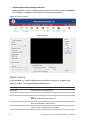
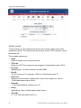
Download UltraView Encoder 10 and UltraView Decoder 10 User Manual

Transcript
UltraView Encoder 10 and
UltraView Decoder 10
User Manual
P/N 1063971 • REV 2.0 • ISS 01MAR11
Copyright
Trademarks and
patents
© 2011 UTC Fire & Security Company. All rights reserved.
Interlogix, UltraView Encoder 10 and UltraView Decoder 10, and
logo are trademarks of UTC Fire & Security.
Other trade names used in this document may be trademarks or
registered trademarks of the manufacturers or vendors of the
respective products.
Manufacturer
UTC Fire & Security Americas Corporation, Inc.
2955 Red Hill Avenue, Costa Mesa, CA 92626-5923, USA
Authorized EU manufacturing representative:
UTC Fire & Security B.V.
Kelvinstraat 7, 6003 DH Weert, Netherlands
FCC compliance
This device complies with part 15 of the FCC Rules. Operation is
subject to the following two conditions: (1) This device may not
cause harmful interference, and (2) this device must accept any
interference received, including interference that may cause
undesired operation.
Class B: This equipment has been tested and found to comply with
the limits for a Class B digital device, pursuant to part 15 of the FCC
Rules. These limits are designed to provide reasonable protection
against harmful interference in a residential installation. This
equipment generates, uses, and can radiate radio frequency energy
and, if not installed and used in accordance with the instructions,
may cause harmful interference to radio communications.
There is no guarantee that interference will not occur in a particular
installation. If this equipment does cause harmful interference to
radio or television reception, which can be determined by turning the
equipment off and on, the user is encouraged to try to correct the
interference by one or more of the following measures:
•
•
•
•
European Union
directives
Reorient or relocate the receiving antenna.
Increase the separation between the equipment and receiver.
Connect the equipment into an outlet on a circuit different from
that to which the receiver is connected.
Consult the dealer or an experienced radio/TV technician for
help.
1999/5/EC (R&TTE directive): Hereby, UTC Fire & Security
declares that this device is in compliance with the essential
requirements and other relevant provisions of Directive 1999/5/EC.
2002/96/EC (WEEE directive): Products marked with this symbol
cannot be disposed of as unsorted municipal waste in the European
Union. For proper recycling, return this product to your local supplier
upon the purchase of equivalent new equipment, or dispose of it at
designated collection points. For more information see:
www.recyclethis.info.
Contact information
Customer support
For contact information, see www.interlogix.com.
[email protected] (EMEA)
[email protected] (USA)
[email protected] (Australia)
[email protected] (China and Hong Kong)
Content
Overview 3
Introduction 3
Product content 3
Hardware requirements 3
Software requirements 4
Before you begin 4
References and related documentation 4
UltraView Encoder 10 5
Physical description and technical specifications 5
Functionality and features 6
Interface ports 7
UltraView Decoder 10 9
Physical description and technical specifications 9
Functionality and features 10
Interface ports 11
Installing the unit 13
Packing list 13
Installation 13
Connecting the power supply 16
Connecting the unit 17
Unit front panel 17
Unit back panel 18
Back panel module connectors 18
Connecting the unit 19
Front panel LED 20
LED colors 20
Selected LED modes and scenarios 21
Starting and configuring the unit 22
Start the unit 22
Accessing the extended web server 23
Accessing and monitoring the unit 24
Homepage 24
Live view (UltraView Encoder 10 with VOS 4.2 or later) 24
Health monitoring 25
System configuration 27
Video ports 28
Network interfaces 28
UltraView Encoder 10 and UltraView Decoder 10 User Manual
i
Configuring the unit 29
Configuration 29
Network configuration 29
Video inputs 31
Video analytics 33
Digital inputs 34
Relay outputs 35
Serial ports 36
System security 38
Firmware update 39
Configuration download 40
Event Manager 40
NTP Server 41
Restart 41
Clear 41
Help 41
Contacting technical support 42
Glossary 43
ii
UltraView Encoder 10 and UltraView Decoder 10 User Manual
Overview
Introduction
The UltraView Encoder 10 and UltraView Decoder 10 are part of a mobile
surveillance solution that addresses the needs of remote site applications
typically found in highway, transportation, and city surveillance. These
applications form the backbone of the deployed UltraView EVP solutions.
UltraView Encoder 10 and UltraView Decoder 10 are compatible with other
UltraView EVP products and have:
•
•
•
Scalable H.264 SVC streaming / H.264-SVC video decoder
Low latency with max of <150 ms
Upgradable platform
Also support:
•
•
PTZ port, alarm input, and relay output
Basic analytics
and can operate in various environmental conditions, for example, it can be used
indoors within a light industrial environment.
Two models are available:
•
UltraView Encoder 10 unit is a small size form-factor single channel encoder.
It comprises a DM6446, capable of converting a PAL or NTSC analog video
input to digital, scaling and compressing it to H.264 SVC.
•
UltraView Decoder 10 unit is a small size form-factor single channel decoder,
capable of converting a H.264 SVC stream into a PAL or NTSC analog video
output.
Note: The USB port is used as an extension port, enabling a full range of
additional features, all accessed through the main unit. Currently not available,
reserved for future use.
Product content
The unit package includes:
•
•
1 box containing the unit and installation sheet
1 box containing 12 VDC power supply (optional)
Hardware requirements
The unit requires the following:
•
•
•
Cat 5 network cable
110 V or 220 V main power supply or 12 VDC power supply
BNC video cable
UltraView Encoder 10 and UltraView Decoder 10 User Manual
3
Software requirements
The UltraView Encoder 10 unit requires the following:
•
•
UltraView Central Configuration Server version 4.1.1 (or later) or UltraView
Video Security Center version 4.1.1 (or later)
NTP Server
The UltraView Decoder 10 unit requires the following:
•
•
UltraView Central Configuration Server version 4.2 (or later) or UltraView
Video Security Center version 4.2 (or later)
NTP Server
Before you begin
Inspect the package and contents for visible damage. If any components are
damaged or missing, do not use the unit; contact the supplier immediately. If you
need to return the unit, you must ship it in the original box.
References and related documentation
•
•
UltraView Central Configuration Server (CCS) user manual
UltraView Video Security Center (VSC) user manual
Note: Always consult the technical support team before making any hardware
configuration changes; as this may void warranty against damages and limit
support.
4
UltraView Encoder 10 and UltraView Decoder 10 User Manual
UltraView Encoder 10
Physical description and technical specifications
This section provides detailed specifications of UltraView Encoder 10.
Figure 1: UltraView Encoder 10
Video input
•
PAL or NTSC analogue camera
Video encoding
•
•
•
•
•
H.264-SVC (Spatial & Temporal scalability)
Unicast and multicast connection
Resolution up to 4CIF
Frame rates up to 30 (NTSC) or 25 (PAL)
Bit rates up to 3 Mbps
Security
•
Password protection for restricted access to setup and management.
Installation, management, and maintenance
•
Internet Explorer 5.x (or later)
System integration
UltraView Encoder 10:
•
UltraView SDK 4.1.1 (or later)
Supported protocols
•
HTTP, TCP, UDP, IGMP, SMTP, DHCP, DNS
UltraView Encoder 10 and UltraView Decoder 10 User Manual
5
Connectors
•
•
•
•
•
•
•
•
Ethernet 10BaseT or 100BaseTX (RJ-45)
USB 2.0 Hi-Speed (host, Mini-A)
Terminal connector (Phoenix P/N: FK-MC 0,5/9-ST-2,5)
BNC composite video
Power 8-16 VDC, min. 5 W
1 dry contact input
1 open collector output
1 serial (RS-485)
Processors and memory
•
•
•
•
CPU: TI DM6446
System: Linux 2.6 kernel
RAM: 128 MB
Flash memory: 32 MB
Operating conditions
•
•
Temperature: −10°C (14°F) to 50°C (122°F)
Humidity: 20% to 80% RH (non-condensing)
Dimensions (H × W × D) and weight
•
•
19 × 72 × 95 mm
300 g (excluding power adapter)
Power supply and consumption
The UltraView Encoder 10 is equipped with a 12 VDC, 5 W power supply. Power
consumption is 5 W (full-load across the whole temperature range).
There is no on-board battery to secure data retention when the power is off. The
time and date synchronization is done through a NTP server on the network, and
this server is necessary for the correct operation of UltraView Encoder 10.
Functionality and features
UltraView Encoder 10 represents an extension of the UltraView EVP family of
digital video devices, providing customers with a single channel real-time
embedded Digital Video Server (DVS) utilizing the scalable H.264 video
compression developed within the H.264 SVC program.
Main product features are:
•
•
•
•
•
•
6
Video surveillance system: 1 channel input
Mechanical system: Self contained unit
Ethernet connectivity: 10/100 Ethernet port
GUI: Embedded Web Server for basic configuration
I/O connectivity: Dry contact and RS-485 serial port
Electrical: 12 VDC, 5 W power supply
UltraView Encoder 10 and UltraView Decoder 10 User Manual
Encoding
UltraView Encoder 10 resides on an IP network. The product primary purpose is
to convert PAL or NTSC analog video source to IP video.
Analytics
UltraView Encoder 10 support embedded analytics.
This includes the established EVP analytics:
•
•
Activity Detection (AD)
Camera Maintenance Agents (CMA)
These analytics are embedded on the DaVinci chip instead of being run on a PC
platform.
Configuration
The unit is normally configured from CCS. Default configuration is set to D1 PAL
at 2 Mbps at 25 fps. The unit is designed to connect video, power on, and stream
video automatically via a static address. Additionally, there is support for DHCP
and a fixed IP address configuration via a web browser.
Interface ports
Camera input channels
•
•
•
•
•
•
•
Input format: PAL or NTSC
Input connection: BNC
Input signal type: Vp-p at 75 Ω
Frame rate (capture): Frame rates up to 30 (NTSC) or 25 (PAL)
Color system: Color, black & white and monochrome
Number of video channels: 1
Power supply: Not required
Digital inputs
•
•
•
Number: 1
Type: TTL (compliant with 48 V input voltage)
Connector Type: Pin terminal
Digital outputs
•
•
•
Number: 1
Type: Open collector (compliant with 48 V external power)
Connector type: Pin terminal
Serial ports
•
•
•
Number: 1
Type: RS-485 Master input or output pass through
Connector type: Pin terminal
UltraView Encoder 10 and UltraView Decoder 10 User Manual
7
USB ports
•
•
Number: 1
Type: USB 2.0 Hi-Speed (host, Mini-A)
Ethernet ports
•
•
•
Number: 1
Type: 802.3 type 10/100 Mbps (RJ-45)
DHCP: Yes
Status
The following LED is visible on the front panel
•
Status LED: Green or Red (see section “Front panel LED” on page 20 for
more information)
Factory reset
•
•
8
Number: 1
Type: Pinhole
UltraView Encoder 10 and UltraView Decoder 10 User Manual
UltraView Decoder 10
Physical description and technical specifications
This section provides detailed specifications of UltraView Decoder 10.
Figure 2: UltraView Decoder 10
Video output
•
PAL or NTSC analogue camera
Video decoding
•
•
•
•
H.264-SVC video stream
Resolution up to 4CIF
Frame rates up to 30 (NTSC) or 25 (PAL)
Bit rates up to 3 Mbps
Security
•
Password protection for restricted access to setup and management.
Installation, management and maintenance
•
Internet Explorer 5.x (or later)
System integration
•
UltraView SDK 4.2.0 (or later)
Supported protocols
•
HTTP, TCP, UDP, IGMP, SMTP, DHCP, DNS
Connectors
•
•
•
•
Ethernet 10Base-T/100Base-TX (RJ-45)
USB 2.0 Hi-Speed (host, Mini-A)
Terminal connector (Phoenix P/N: FK-MC 0,5/9-ST-2,5)
BNC composite video
UltraView Encoder 10 and UltraView Decoder 10 User Manual
9
•
•
•
•
Power 8-16 VDC, min. 5 W
1 dry contact input
1 open collector output
1 serial (RS-485)
Processors and memory
•
•
•
•
CPU: TI DM6446
System: Linux 2.6 kernel
RAM: 128 MB
Flash memory: 32 MB
Operating conditions
•
•
Temperature: −10°C (14°F) to 50°C (122°F)
Humidity: 20-80% RH (non-condensing)
Dimensions (H × W × D) and weight
•
•
19 × 72 × 95 mm
300 g excluding power adapter
Power supply and consumption
The UltraView Decoder 10 is equipped with a 12 VDC, 5 W power supply.
Power consumption is 5 W (full-load across the whole temperature range)
There is no on-board battery to secure data retention when power is off. The time
and date synchronization is done through a NTP server on the network, and this
server is necessary for the correct operation of UltraView Decoder 10.
Functionality and features
UltraView Decoder 10 represents an extension of the UltraView EVP family of
digital video devices, providing customers with a single channel embedded video
decoder, compatible with any stream of the H.264 SVC product family.
Main product features are:
•
•
•
•
•
•
Video surveillance system: 1 channel output
Mechanical system: Self contained unit
Ethernet connectivity: 10/100 Ethernet port
GUI: Embedded web server for basic configuration
I/O connectivity: Dry contact and RS-485 serial port
Electrical: 12 VDC, 5 W power supply
Decoding
UltraView Decoder 10 resides on an IP network. The product primary purpose is
to convert an H.264-SVC video stream into a PAL or NTSC analog video signal.
10
UltraView Encoder 10 and UltraView Decoder 10 User Manual
Analytics
UltraView Decoder 10 supports embedded analytics display.
This includes the established analytics:
•
•
Activity Detection
Camera Maintenance Agents
In UltraView Decoder 10, the On Screen Display (OSD) of the analytic result is
embedded on the DaVinci chip and is overlaid over the video signal.
Configuration
The unit is normally configured from CCS. Default configuration displays a GE
logo. The unit is designed to connect video, power on and stream video
automatically via a static address. Additionally, there is support for DHCP and a
fixed IP address configuration via a web browser.
Interface ports
Camera output channels
•
•
•
•
Output format: PAL or NTSC
Video connection: BNC
Output signal type: Vp-p at 75 Ω
Number of video channels: 1
Digital inputs
•
•
•
Number: 1
Type: TTL (compliant with 48 V input voltage)
Connector Type: Pin terminal
Digital 0utputs
•
•
•
Number: 1
Type: Open collector (compliant with 48 V external power)
Connector type: Pin terminal
Serial ports
•
•
•
Number: 1
Type: RS-485 master input or output pass through
Connector type: Pin terminal
USB ports
•
•
Number: 1
Type: USB 2.0 Hi-Speed (host, Mini-A)
Ethernet ports
•
•
•
Number: 1
Type: 802.3 type 10/100 Mbps (RJ-45)
DHCP: Yes
UltraView Encoder 10 and UltraView Decoder 10 User Manual
11
Status
The following LED is visible on the front panel:
•
Status LED: Green and red, see section “Front panel LED” on page 20 for
more information
Factory reset
•
•
12
Number: 1
Type: Pinhole
UltraView Encoder 10 and UltraView Decoder 10 User Manual
Installing the unit
UltraView Encoder 10 and UltraView Decoder 10 units come with all applicable
parts installed. The hardware installation procedure consists of mounting the
video equipment on a wall or using DIN rail adapters.
Packing list
The following items should be included with each UltraView Encoder 10 and
UltraView Decoder 10 package:
•
•
1 UltraView Encoder 10 or UltraView Decoder 10 unit
1 installation sheet
Note: Power supply needs to be ordered separately.
Installation
Caution: Make sure that the equipment is turned off before proceeding.
To install the wall mount:
1. Lift the unit safely out of the packing container.
2. As you unpack the unit, check for signs of shipping damage (damaged box,
scratches, dents, etc.). If the unit is damaged or fails to meet specifications,
notify the Interlogix support team or your local representative immediately.
Also notify the carrier. Retain the shipping cartoon and packing material for
inspection by the carrier.
3. Ensure the power service at the site is suitable for the video equipment you
are installing.
4. Check the packing slip to ensure that all the proper components are present.
The wall bracket is by default attached to the unit.
5. It can be easily removed by bending the bracket itself. This may help with the
mounting procedure.
UltraView Encoder 10 and UltraView Decoder 10 User Manual
13
Figure 3: Wall bracket
6. Mount the wall bracket on the wall using appropriate screws (not included).
7. Attach the unit to the wall bracket using appropriate fixation points, see
Figure 4 below.
Figure 4: Attach device to the bracket
To install the DIN rail adapters:
1. For horizontal mount, attach the DIN rail adapter to the wall mount bracket
using the holes in the bracket. See Figure 5 on page 15.
Note: you must first detach the mount bracket to get access to the fixation holes.
2. Mount the DIN rail on the rack.
14
UltraView Encoder 10 and UltraView Decoder 10 User Manual
Figure 5: Attach the adapter for horizontal mount
3. For vertical mount, attach the DIN rail adapter to the wall mount bracket using
the holes in the bracket, see Figure 6 below.
Note: you must first detach the mount bracket to get access to the fixation holes.
4. Mount the DIN rail on the rack.
Figure 6: Attach the adapter for vertical mount
Mounting points on the bracket
Figure 7 on page 16 shows three methods of attaching the unit to the wall
bracket and to the horizontal mount and vertical mount adapters. Attach points
(for all the methods) are highlighted by different numbers.
UltraView Encoder 10 and UltraView Decoder 10 User Manual
15
Figure 7: Mounting points on the bracket
1. Attach to adapter for horizontal mount.
2. Attach to adapter for vertical mount.
3. Attach to the unit for wall mount.
Connecting the power supply
To connect power supply:
1. Connect the power cable to the power supply connector situated on the back
of the unit.
•
•
Pin 1 = GND
Pin 2 = 12 VDC
See Figure 10 on page 18 for the back panel connectors.
2. Connect the opposite end of the power cable to an appropriate power source.
The input power to the chassis is self-sensing and should be 110 to 230 V,
50 to 60 Hz.
Note: The socket outlet should be installed near the unit and be easily
accessible.
16
UltraView Encoder 10 and UltraView Decoder 10 User Manual
Connecting the unit
Unit front panel
UltraView Encoder 10
The UltraView Encoder 10 front panel contains (see Figure 8 below):
•
•
•
A single BNC (75 Ω) video input connector, item 1.
A single status LED, see item 2 (see section “Front panel LED” on page 20
for more information on LED status).
A pinhole factory reset, see item 3. To reset the device to factory
configuration press and hold the reset button for 5 sec. The factory default
access settings are:
• http://10.1.2.11
• Network mask: 255.255.0.0
• Administration login: admin
• Password: admin
• PAL 4CIF 2 Mbps video encode
Figure 8: UltraView Encoder 10 front panel
UltraView Decoder 10
The UltraView Decoder 10 front panel contains (see Figure 9 on page 18):
•
•
•
•
A single BNC (75 Ω) video output connector, see item 1.
A single status LED, see item 2 (see section “Front panel LED” on page 20
for more information on LED status).
A pinhole factory reset, see item 2. To reset the device to factory
configuration press and hold the reset button for 5 sec. The factory default
access settings are:
• http://10.1.2.11
• Network mask: 255.255.0.0
• Administration login: admin
• Password: admin
GE logo display
UltraView Encoder 10 and UltraView Decoder 10 User Manual
17
Figure 9: UltraView Decoder 10 panel
Unit back panel
All device functions are accessible via the back panel. For UltraView Encoder 10
and UltraView Decoder 10 back panel, see Figure 10 below.
The UltraView Encoder 10 and UltraView Decoder 10 back panel contains:
•
•
•
A single RJ-45 Ethernet (Cat 5), see item 1.
A single USB 2.0 port (host only), see item 2, reserved for future extensions
Pin terminal (Phoenix P/N: FK-MC 0,5/9-ST-2,5), see item 3, used for:
• DC power connection
• Dry contact input
• Open collector output
•
Serial connection (RS-485)
Figure 10: UltraView Encoder 10 and UltraView Decoder 10 back panel connectors
Back panel module connectors
The peripheral devices are connected by the pin terminal (Phoenix P/N: FK-MC
0,5/9-ST-2,5) or and the RJ-45 Ethernet port.
In the back panel module, pins are numbered from left to right when facing the
interface module.
18
UltraView Encoder 10 and UltraView Decoder 10 User Manual
Figure 11: The Interface module connector
Detailed specifications for the module’s pins are provided in Table 1 below.
Table 1: Pin description
Pin number connector
1
2
3
4
5
6
7
8
9
Description
DC − (GND)
DC + (12 VDC)
TX TX +
GND
OUT
GND
IN
GND
The following wires must be used with this connector:
•
•
•
Conductor size: 20 to 26 AWG
Solid wire: 0.14 to 0.5 mm²
Stranded wire with ferrule: 0.25 to 0.5 mm²
For stranded wires, it is strongly advised that ferrules with or without plastic
sleeves are used. An automated insertion (plug and play) is only possible with
solid (>0.2 mm²) or stranded wires with ferrules
Connecting the unit
After mounting the unit on the wall or another surface (for example, a rack),
follow the procedure below to connect all the cables and activate the unit.
1. Connect the BNC cable to the BNC video input connector, see item 1 on the
front panel. For UltraView Encoder 10 see Figure 8 on page 17, for UltraView
Decoder 10 see Figure 9, on page 18.
2. Connect the Ethernet cable to the RJ45 Ethernet port, see item 1 on the back
panel, see Figure 10 on page 18.
3. Prepare the terminal cable and plug into the connector, see item 3 on the
back panel, see Figure 10 on page 18.
4. See whether the device is properly connected by checking LED display. See
“Front panel LED” on page 20 for details about LED states.
UltraView Encoder 10 and UltraView Decoder 10 User Manual
19
Front panel LED
On the front panel there is one LED conveying unit status to the user.
Figure 12: Front panel LED
LED colors
Green LED shows the operating state of the equipment. Red LED shows errors
or events that require human intervention. See below for more detailed
information.
Green
Green is used for conveying information about the current state of the equipment.
It should reflect the following general states:
•
•
•
Booting
Updating
Running
Red
Red is used to indicate errors or events that require human intervention:
•
•
•
Not booting
Hardware problems (voltages, temperature)
Not configured
Note: See section “Selected LED modes and scenarios” on page 21 and
“Starting and configuring the unit” on page 22 for details about LED states.
20
UltraView Encoder 10 and UltraView Decoder 10 User Manual
Selected LED modes and scenarios
Table 2: LED modes and scenarios
State
LED
User action
1. Wait max. 2 minutes
Booting
Fixed green
Updating
1. Wait max. 5 minutes
Green heartbeat or
VOS running - no
video detected
(100 ms on, 100
ms off)
VOS running video detected
(500 ms on, 500
ms off)
Factory reset
button pressed
VOS is running but
no configuration
available
Voltage or
temperature alarm
Fast green blinking
1. Check camera is
connected
2. Check the power is on
Slow green blinking
Simple user feedback
Red Double Heartbeat
Slow green (with red) blinking
Red heartbeat
In recovery mode
Red triple heartbeat
Equipment must be
Fixed red
replaced
UltraView Encoder 10 and UltraView Decoder 10 User Manual
1. Connect to CCS or EWS
2. Verify the configuration
3. Configure the equipment
4. Apply the configuration
1. Connect to CCS or EWS
2. Check voltage or
temperature
3. Check logs
4. Check environment
5. Possibly replace device
1. Connect to EWS
2. Check status of recovery
mode
3. Configure IP address of
the device and of CCS
4. Upload firmware through
EWS
Replace device
21
Starting and configuring the unit
This section contains information about the start up procedure and the necessary
software configuration.
Start the unit
To start the unit:
1. Switch on the unit. The front status LED provides feedback on the unit’s
operating conditions.
2. The Video Operating System (VOS) and the service software will then start
up automatically. If the video equipment has been switched on for the first
time, the network parameters need to be configured. Otherwise the Central
Configuration Server will not detect the video equipment on the network.
Table 3: LED states
LEDs
Explanation
Fixed green LED on
Boot in progress
Green LED blinking
Ready
Slow blinking
Video detected
Fast blinking
No video detected
Red triple heartbeat
Boot in recovery mode
Installing on a network
The device is designed for installation on an Ethernet network. This involves
assigning it an IP address, either manually or via an automated network service
(DHCP). Depending on your network, select one of the following procedures:
•
•
Automatic installation using DHCP
Manual Installation using fixed IP address
Note: The device has a default IP address 10.1.2.11. DHCP is disabled by
default.
Monitoring system
The monitoring system is designed to detect abnormal system operating
conditions and generate alarm outputs or messages, allowing users to take the
necessary action before system failure.
The monitoring system can detect a wide variety of internal system conditions
including temperature, voltage, and power supply status. It can generate several
different alarm outputs, including sending out alarm messages through the serial
port for remote notification. SNMP traps are also available.
22
UltraView Encoder 10 and UltraView Decoder 10 User Manual
Accessing the extended web server
To access the web server for the device, the default fixed IP address is:
http://10.1.2.11
Figure 13 below presents the homepage for UltraView Encoder 10, seen after
connecting to the web server.
Figure 13: Embedded web server homepage
UltraView Encoder 10 and UltraView Decoder 10 User Manual
23
Accessing and monitoring the unit
Homepage
On the homepage, these menu options are available (the menu options are also
available in other widows):
•
•
•
•
•
Home - return to homepage
Live view (UltraView Encoder 10 only) - display the live stream
Health monitoring - used for monitoring the health of the device
Configuration - used for login in, network configuration, setting/changing
access rights, and setting video formats
Restart - used for restarting the device (for example, for changes to take
effect)
Home
Select Home to return the extended web server to the starting screen.
Live view (UltraView Encoder 10 with VOS 4.2 or later)
Note: Not available in some devices.
In this window you can display a live stream from the selected device. You can
also control PTZ movement, set zoom, focus, and iris (as well as set and save
PTZ presents).
You need to have the VLC Media Player Mozilla and ActiveX Plugin installed to
display the video. See this link www.videolan.org for more information.
Note: When streaming video using VLC Player, the MTU size of the network
interface must be configured to a value of less than 10,000.
To get live video, you need to use one of the following browsers:
•
Internet Explorer 7.0 or higher
The available options are:
•
RTSP stream links
Select RTSP stream from the drop down menu. Start or Stop the stream.
•
Show current Pan, and Zoom values (only available in some models)
Displays the current camera position and zoom values on the stream video.
•
Set Pan, Tilt, Zoom, Focus, and Iris values (only available in some models)
Control the PTZ camera position, zoom, focus, and iris (light exposure), using
an online control panel associated with Live view.
•
Store PTZ values as specified presets (only available in some models)
Store current camera position and other settings (PTZ values) as presets,
using a specific name (up to 10 presets for each device).
•
List PTZ presets (only available in some models)
View all the preset names defined by any user.
24
UltraView Encoder 10 and UltraView Decoder 10 User Manual
•
Recall a PTZ preset (only available in some models)
Select a preset name from the PTZ list and set camera position defined by
this preset.
•
Change display size
If available, you can set sub-resolutions to request specific video size
streams.
Figure 14: Live view
Health monitoring
Select Health monitoring in the homepage menu to be directed to the Health
monitoring window. These monitoring options are available:
•
•
•
•
Health monitoring - monitors the health status of the device
System configuration - monitors system configuration and status
Video ports - monitors video ports status and configuration
Network interfaces - monitors the network interface status and configuration
UltraView Encoder 10 and UltraView Decoder 10 User Manual
25
Health monitoring
In the Health monitoring window you have access to information about the status
of the system. The following information is provided by the system:
Value
Description
CPU temperature
Current temperature of the main processor.
Core voltage
Power supply voltage supplied to the device.
Power supply voltages (+1.2 V, +1.8
V, +5 V, +12 V)
Reference voltage values required by the device.
Free memory
Indicates the amount of free memory available.
CPU usage
Indicates the percentage of time the processor is working.
System date and time
Indicates the current system date and time.
Uptime
Indicates how long the device has been active
Note: Green value means status is OK and within suitable range. Red value
means status is outside the normal operating range. If the value is red and an
alarm is generated, the user can acknowledge the alarm by clicking on the red
value. The value changes to orange and an alarm acknowledged message is
generated.
Figure 15: Health metrics window
26
UltraView Encoder 10 and UltraView Decoder 10 User Manual
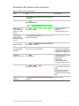
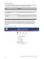
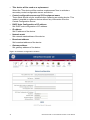
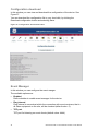
System configuration
In the System configuration window you can display the configuration of any
video equipment.
The following information is provided by the system:
Value
Description
Equipment name
Unique name of the device.
Serial number
Unique serial number of the device.
Software revision
Video operating system version.
U-Boot revision
Indicates the booting software version.
Software recovery revision
Video operating system version to which the system will revert,
after failure.
Memory size
Memory available on the device.
Number of fans (motherboard) Number of fans used on the motherboard.
Power supply units
Number of supply units used.
Figure 16: System configuration window
UltraView Encoder 10 and UltraView Decoder 10 User Manual
27
Video ports
In the Video ports window you have access to information about video ports.
Figure 17: Video ports window
Network interfaces
In the Network interfaces window you have access to information about the
available network interfaces.
Figure 18: Network Interfaces window
28
UltraView Encoder 10 and UltraView Decoder 10 User Manual
Configuring the unit
Configuration
In this window you can set various system and video configuration options, such
as network configuration, system security, event manager’s configuration, and
configuration access and video port configuration.
Note: The default login is “admin” and the default password is “admin”.
The available options are:
•
•
•
•
•
•
•
•
•
•
•
Network configuration
Video inputs
Video analytics
Digital inputs
Digital outputs
Serial Ports
System security
Firmware update
Configuration download
Event manager
NTP server
Network configuration
In this window you can set the network configuration for the device.
Note: Network settings will take effect on the next system restart.
Note: If the system becomes unreachable because of an IP address or network
configuration problem, you can try the default IP address (10.1.2.11,
255.255.255.0) or you can push the reset factory button to reset all settings to
default.
The available options are:
•
Fully qualified host name
Define a unique name of the fully qualified host. This field should include a
domain name, if possible.
•
DNS server
Define a comma separated list of DNS servers IP addresses. Primary server
should be added first. DNS-less operation is supported, but with the
restriction that other equipment and CCS must be configured with static IP
addresses.
•
DNS search path
When a hostname is specified with a domain name, the domain of this host
will be searched as well as the other domains defined in this field.
UltraView Encoder 10 and UltraView Decoder 10 User Manual
29
•
This device will be used as a replacement
Select the "This device will be used as a replacement" box to activate a
secondary central configuration server and device.
•
Central configuration server and CCS equipment name
These fields should only be modified when replacing an existing device. This
makes it possible to replace a device without any intervention from the
Central Configuration Server.
•
DHCP Auto Configuration of IP address
Set DHCP auto configuration of IP address.
•
IP address
Set IP address of the device.
•
Network mask
Set network mask address of the device.
•
Broadcast address
Set broadcast address of the device.
•
Gateway address
Set gateway address of the device
Figure 19: Network configuration window
30
UltraView Encoder 10 and UltraView Decoder 10 User Manual
Video inputs
In this window you can set video input parameters.
To set video inputs:
1. Set capturing parameters
2. Add slave inputs, up to 4 (if needed)
3. Set master input parameters for a stream
4. Set slave input parameters for a stream
5. Click Apply to set the parameters or Remove to delete input.
The available options are:
Encoding parameters
•
Format
Encoding system used PAL (BGHI) or NTSC (M).
•
FULL/CIF/QCIF
If enabled, the spatial sub-resolution will be encapsulated within the video
stream (for example, if the highest spatial resolution is FULL, enabling lower
resolution will embed CIF & QCIF) It is strongly advised to keep this option
activated, otherwise, the scalability could be reduced, although effective
bandwidth might increase.
•
Bandwidth
Defined target bandwidth.
•
Encoding mode for FULL
Standard: Stream progressive frames (default) 25/30p.
Low bitrate: Stream 2CIF format (1 field only), to save bandwidth (2CIF,
25/30i)
High quality: Stream Interlaced fields to optimize video output quality (FULL,
50/60i)
Streaming parameters
Master input:
•
Name
A unique name of the master input (for each video stream).
•
Streaming FPS
Video streaming rate in frame per second.
•
TCP port
The TCP port defined to stream video.
•
Scale
Sampling resolution: FULL or CIF or QCIF (if applicable).
•
Format
Encoding system used: PAL (BGHI) or NTSC (M).
UltraView Encoder 10 and UltraView Decoder 10 User Manual
31
•
Include subscales
If enabled, the spatial sub-resolution will be encapsulated within the video
stream (for example, if the highest spatial resolution is FULL, enabling lower
resolution will embed CIF & QCIF) It is strongly advised to keep this option
activated, otherwise, the scalability could be reduced, although effective
bandwidth might increase.
•
RTSP session
Real Time Streaming Protocol (RTSP) streaming session.
•
RTSP link
A link to Real Time Streaming Protocol (RTSP) streaming session.
Slave inputs (four can be set):
•
Name
A unique name of the slave input (for each video stream).
•
Streaming FPS
Video streaming rate in frame per second.
•
TCP port
The TCP port defined to stream video.
•
Scale
Sampling resolution: FULL or CIF or QCIF (if applicable).
•
RTSP session
Real Time Streaming Protocol (RTSP) streaming session name.
•
RTSP link
A link to Real Time Streaming Protocol (RTSP) streaming session.
Figure 20: Video inputs
32
UltraView Encoder 10 and UltraView Decoder 10 User Manual
Video analytics
In this window you can set activity detection (AD) parameters.
Note: You need Java Runtime Environment version 1.6 or higher.
The available options are:
•
Enable activity detection
Enable activity detection plugin on video input. The TCP port is read-only.
•
Video Input
Select the video stream on which activity detection will be activated.
•
Activity detection modes
Set the activity detection area to full screen or ROI (region of interests).
•
Set sensitivity
Set sensitivity of detected activity in the plug-in. Three predefined values can
be set: LOW, MEDIUM, and HIGH.
•
Set activation interval
Set a time period (sample interval) after which the alarm is triggered if activity
is detected. Minimum value is 20 ms.
•
Define minimum alarm time
Define the minimum time after the AD is activated, before an alarm is
triggered.
•
Define minimum and maximum change size in %
Define the minimum and maximum size of activity detected area (calculated
in % of pixels).
•
Define ROI by drawing a basic shape (rectangle, polygon or hexagon)
Define ROI (region of interest) of activity detection, by drawing an appropriate
shape on the screen. Click and move cursor to draw a region. ROI can be
selected as a polygon, rectangle and hexagon. Use select radio button to
select specific image. Multiple region of interests can be drawn on a single
screen.
•
Activate bad exposure detection
Select this box to activate bad exposure detection on the stream.
•
Verification interval
Enter the time required to confirm that enough pixels values have changed
(ms).
•
Under exposure
Select this box to activate under exposure detection, when there is a loss of
detail due to dark parts of an image being all black. The TCP port is readonly.
•
Over exposure
Select this box to activate over exposure detection, when there is a loss of
detail due to bright parts of an image being all white. The TCP port is readonly.
UltraView Encoder 10 and UltraView Decoder 10 User Manual
33
•
Activate permanent change detection
Select this box to detect a permanent change of the scene under investigation
(for example, a change in the camera's centering and position).
Figure 21: Video analytics
Digital inputs
In this window you can list digital inputs and define a name for a digital input
change of state. The displayed parameters will be:
Parameters
Description
Input name
Unique name for the digital input.
TCP port
TCP port used for digital inputs.
Line
A number identifying a configured digital input used for signal
input.
Note: Not available in some devices.
Poll interval
Line state refresh period in ms.
Note: Not available in some devices.
Event name (low to high)
Defines an event name for the change of state on the digital input
(when the input changes from low to high).
34
UltraView Encoder 10 and UltraView Decoder 10 User Manual
Event name (low to high)
Defines an event name for the change of state on the digital input
(when the input changes from high to low).
Figure 22: Digital inputs
Relay outputs
In this window you can define an event that will trigger a change on output.
The displayed parameters will be:
Parameters
Description
Input name
Unique name for the digital output.
TCP port
TCP port used for digital output.
Device type
Whether USB device or other.
Initial state
The initial relay state at startup.
Line
A number identifying a configured digital input used for signal input.
Note: Not available in some devices.
In this window you can also set:
•
Name
Define the name of the event, which triggers this relay action.
•
Action type
Define whether the action is open or closed.
•
Action time (MS)
Duration of the action in milliseconds (MS). Value “0” means it is permanent.
Click Apply to set an event. Add, save or remove an event using appropriate
buttons.
UltraView Encoder 10 and UltraView Decoder 10 User Manual
35
Figure 23: Relay outputs
Serial ports
In this window you can configure the serial communication ports of the video
equipment used for connecting telemetry devices, such as PTZ cameras, control
keyboards, etc.
The available options are:
•
Name
Define a unique name for the serial port.
•
TCP port
Define the TCP Port number for the reception of data (default value: 8501).
•
Port type
Signaling type. For these devices it will be RS485.
•
Port ID
The ID of the port. For example, COM1 for UltraView Encoder 10.
•
Baud rate
Speed at which the data is transmitted. Value in the range from 1200 to
115200 bps (default value: 2400).
•
Data bits
7 or 8 bit data packets (default value: 8).
•
Parity
Select Even, Odd, or None (default value: None).
•
Stop bits
0, 1 or 2. stop bits (default value: 1).
36
UltraView Encoder 10 and UltraView Decoder 10 User Manual
•
Flow control
Select the Flow Control option from the drop down menu. Flow control
compensates for the difference between the rate at which data reaches a
device and the rate at which the device processes and transmits. The two
common types of flow control are RTS/CTS signaling (a hardware based
method, employing an electrical signal) and XON/XOFF (a software-based
method using standard ASCII control characters to pause or resume
transmission).
•
PTZ camera
Set for PTZ cameras.
•
Camera name
Define a unique PTZ camera name.
•
Camera TCP port
Define a PTZ TCP port.
•
PTZ camera protocol
From the drop down list select the PTZ protocol to be used.
Figure 24: Serial ports
UltraView Encoder 10 and UltraView Decoder 10 User Manual
37
System security
In this window you can configure the security settings for the device.The
available options are:
Reset password
In this section you can a set a new unique password.
Note: If you loose or forget your administrative password, you will only be able to
reset it using the reset factory button.
To set new password:
1. Enter old password
2. Enter new password
3. Confirm new password
4. Click Save password
Configuration Access
In this section you can select the check box to only allow device configuration
through EWS. Click save configuration access to store this option.
HTTPS Settings
In this section you can set EWS security policy. Access to EWS will be managed
via HTTP (non-secure) or HTTPS (secure).
Note: The system starts working using the HTTP mode.
A self-signed certificates are treated as untrusted and the browser will give the
user a warning that this connection is unsecure.
To generates and installs self-signed or CA-signed trusted certificates:
1. Click the Generate & install self-signed certificate button
2. Fill out the Generate & install self-signed certificate form
3. Generate and save the certificate
4. Browse for the self-signed certificate
5. Install self-signed certificate
OR
1. Click the Generate certificate signing request button
2. Fill out the Generate certificate signing request
3. Generate and save the certificate signing request
4. Email the certificate signing request to CA
5. Browse for the CA -signed certificate
6. Install CA-signed certificate
You can set security policy as HTTP (non-secure) or HTTPS (secure).
38
UltraView Encoder 10 and UltraView Decoder 10 User Manual
Figure 25: System security window
Firmware update
In this window you can upload a new firmware. See Figure 26.
This will reset the firmware part of flash memory, but all settings will be kept. The
system will download the image and restart automatically after the upgrade.
Note: If the device is reset or power is lost during the update, the device will
switch to recovery mode and a new update should be made using Central
Configuration Server or this web server.
Figure 26: Firmware update window
UltraView Encoder 10 and UltraView Decoder 10 User Manual
39
Configuration download
In this window you can view and download the configuration of the device. See
Figure 27.
You can download the configuration file to your local disk, by clicking the
Download configuration button and selecting Save.
Figure 27: Configuration download window
Event Manager
In this window you can configure the event manger.
The available options are:
•
Enabled
Define whether to enable event manager for the device.
•
Ping interval
Ping interval in seconds at which the connection with event receivers, that is
all video equipment on the site, will be checked (default value: 5).
•
TCP port
TCP port for listening on event clients (default value: 4444).
40
UltraView Encoder 10 and UltraView Decoder 10 User Manual
Figure 28: Event manager window
NTP Server
Specify the location of the NTP server.
Figure 29: NTP server window
Restart
In this window you can reboot the device and re-apply configuration changes. To
apply changes press “OK” in the Restart window.
Clear
Clears all temporary settings and fields that have not been applied and saved.
Help
In this window you can display topic sensitive help, which explains various
functional options, fields and terms used in Extended Web Server.
UltraView Encoder 10 and UltraView Decoder 10 User Manual
41
Contacting technical support
For help installing, operating, maintaining, and troubleshooting this product, refer
to this document and any other documentation provided. If you still have
questions, contact us during business hours (Monday through Friday, excluding
holidays).
Note: Please be ready at the unit before calling.
Table 4: Technical support
North America
Latin America
T: 888 GE Security (888.437.3287) Toll-free in T: +1.305.593.4301
the US, Puerto Rico, and Canada.
F: +1.305.593.4300
503.885.5700 outside the toll-free area.
E: [email protected]
F: 888.329.0332 (Tualatin tech support)
[email protected]
561.998.6232 (Boca Raton tech support)
E: [email protected]
Australia, New Zealand
Europe, Middle East, and Africa
E: [email protected]
T: + 48 (58) 326 2240
F: + 48 (58) 326 2241
E: [email protected]
W: www.interlogix.com
Asia and Hong Kong
E: [email protected]
42
UltraView Encoder 10 and UltraView Decoder 10 User Manual
Glossary
CODEC
Compressor/Decompressor, any technology for compressing and decompressing
data
COM
The name of a serial communication port
CPU
Central Processing Unit, the brain of the computer where most calculations take
place
EVP
Enterprise Video Platform
DHCP
Dynamic Host Configuration protocol, a protocol for assigning IP addresses to
devices on a network
I/O
Input/Output
IP
Internet protocol that specifies the format of packets, also called datagrams and
addressing scheme
LAN
Local Area Network, a network spanning a small physical area and operating at high
speed
LED
Light Emitting Diode
SNMP
Simple Network Management Protocol, a set of protocols for managing complex
networks
USB
Universal Serial Bus
VOS
Video Operating System, UltraView EVP global solution for video security
UltraView Encoder 10 and UltraView Decoder 10 User Manual
43