1
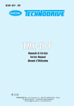
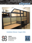
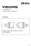
Divisione
ELCO
S.r.l.
USER MANUAL
Control System for EMS
µRUN_CRD
File: MN001509ENG.doc
DATE
23.05.05
CONTROL SYSTEM FOR EMS
µRUN_CRD
USER MANUAL
µRUN SYSTEM
PAGE
1/26
Divisione
ELCO
S.r.l.
USER MANUAL
Control System for EMS
µRUN_CRD
File: MN001509ENG.doc
DATE
23.05.05
PAGE
2/26
CONTENTS
CONTENTS _________________________________________________________________________________ 2
GENERAL __________________________________________________________________________________ 3
WARNING AND CAUTION NOTES ____________________________________________________________ 4
WARNING_________________________________________________________________________________ 4
CAUTION _________________________________________________________________________________ 4
IDENTIFICATION LABEL ____________________________________________________________________ 5
INTRODUCTION TO THE SYSTEM____________________________________________________________ 6
MODULO RACK_CRD _______________________________________________________________________ 7
ELECTRICAL CHARACTERISTICS __________________________________________________________________ 7
ASSEGNAZIONE SLOTS _________________________________________________________________________ 8
SPLY_CRD CARD___________________________________________________________________________ 11
TERMINAL STRIP AND CONNECTORS _____________________________________________________________ 11
ELECTRICAL CHARACTERISTICS _________________________________________________________________ 12
FAILURES OR IMPROPER OPERATIONS ____________________________________________________________ 12
PAM_CRD CARD ___________________________________________________________________________ 13
PAM_CRD OPERATING MODES ________________________________________________________________
TERMINAL STRIPS AND CONNECTORS ____________________________________________________________
ELECTRICAL CHARACTERISTICS _________________________________________________________________
PAM CARD - PROJECT HELP __________________________________________________________________
13
14
16
17
COM_CRD CARD ___________________________________________________________________________ 18
COM_CRD OPERATING MODES ________________________________________________________________ 18
TERMINAL STRIPS AND CONNECTORS ____________________________________________________________ 20
ELECTRICAL CHARACTERISTICS _________________________________________________________________ 21
AVGT_CRD CARD __________________________________________________________________________ 22
TERMINAL STRIPS AND CONNECTORS ____________________________________________________________ 22
ELECTRICAL CHARACTERISTICS _________________________________________________________________ 23
µRUN SYSTEM
Divisione
ELCO
S.r.l.
USER MANUAL
Control System for EMS
µRUN_CRD
File: MN001509ENG.doc
DATE
23.05.05
PAGE
3/26
GENERAL
• This Manual is an integral and essential part of the product. Please read carefully
the instructions contained since they provide important information about safety in
installation, use and maintenance.
• This equipment shall only be destined to the use it was expressly designed for .
Any other use is to be considered incorrect and therefore dangerous.
• The Manufacturer shall not be held responsible for any damages caused by
improper, incorrect or unreasonable use.
• Divisione ELCO srl shall be responsible of this equipment in its original
configuration. Any action that modifies the structure or the operating cycle of this
equipment shall be carried out or by the Technical Department of Divisione Elco
srl or under their explicit authorisation.
• Divisione Elco srl shall not be held responsible for the consequences resulting
from the use of non-original spare parts.
• Any repair shall be carried out by the authorised department of Divisione Elco srl.
The Manufacturer shall not guarantee any repair carried out outside this
department.
• The contents of this Manual are subject to modifications at any moment as it might
be required and without prior notice from the Divisione ELCO srl
• If typing errors or any other errors are found, the rectification will be included in the
new releases.
µRUN SYSTEM
Divisione
ELCO
S.r.l.
USER MANUAL
Control System for EMS
µRUN_CRD
File: MN001509ENG.doc
DATE
23.05.05
PAGE
4/26
WARNING AND CAUTION NOTES
WARNING
• Tampering or modifications or repairs by unqualified personnel are not allowed.
• Divisione ELCO srl do not guarantee against any risks deriving from incorrect use
of their products or from the installation, use and maintenance carried out by
unqualified personnel.
• The products described in this Manual are powered. The risks associated to the
use under such conditions are limited if all necessary safety measures are taken.
• Before attempting to service the system, cut power supply of from all circuits by
means of the safety devices installed in the main control panels.
• Do not energise circuits with a higher voltage than specified.
• Higher or lower voltage supply than specified can result in serious damage to
internal components.
• Do not connect wires other than described in the relevant electric diagrams.
• Do not operate without proper earth connections.
CAUTION
• Cable lengths should be calculated for compliance with the specified tolerances.
• All connectors should be suitably tightened. If terminal strips are fitted, terminal
leads must be suitably tightened.
• Operating conditions: in a closed environment , do not install in an area exposed
to corrosive gases.
• System electronic cards must be suitably fitted in the corresponding connectors on
the rack bottom plate. Use provided guide rails for correct insertion.
µRUN SYSTEM
Divisione
ELCO
S.r.l.
USER MANUAL
Control System for EMS
µRUN_CRD
File: MN001509ENG.doc
DATE
23.05.05
IDENTIFICATION LABEL
Each card is provided with an identification label of the type shown below:
The label consists of three main fields: :
1 - logo of the associated µRun System
2 – main characteristics of the card
2.1 – name of the card ...................… PAM, COM, AVGT, SPLY, RACK;
2.2 - family ........................................ CRD;
2.3 – card model ............................... type of controls, operating voltage;
(numerical identification code)
3 – serial number (0000 to 9999);
µRUN SYSTEM
PAGE
5/26
Divisione
ELCO
S.r.l.
USER MANUAL
Control System for EMS
µRUN_CRD
File: MN001509ENG.doc
DATE
23.05.05
PAGE
6/26
INTRODUCTION TO THE SYSTEM
The system consists of 5 main parts :
- RACK This is the aluminium housing with guides for card fitting.
A board is installed on the bottom of the metal frame with SLOTS housing a
number of cards in cascade and connecting them to owner supply and interface
signals. The bottom board also carries the connectors for system cards.
- SPLY Power supplier for the cards installed in the RACK.
- PAM Card for part presence detection and start signals:
- trolley present;
- direct lock/unlock;
- lock/unlock remote control (e.g. from. PLC);
- COM Control management card generating the signals to be transmitted to the moving
units (trolley on overhead lines, etc.)
- AVGT Card for monitoring signal reading from moving units:
- failure 1 (general);
- failure 2 (no continuity to earth);
It is recommended to read thoroughly this Manual before attempting any operation of
installation of the system.
µRUN SYSTEM
Divisione
ELCO
S.r.l.
USER MANUAL
Control System for EMS
µRUN_CRD
File: MN001509ENG.doc
DATE
23.05.05
PAGE
7/26
Modulo RACK_CRD
The RACK_CRD card is the mother board gathering in a suitably designed mechanical
frame the whole system for power supply and distribution to the installed cards (BUS
system). 3 different types of RACK_CRD are available with a different number of slots : 7,
9 and 19 slots.
Electrical characteristics
Reference voltage
Operating frequency
Voltage supply to stabilised CMOS Logic
Voltage supply to control interconnecting signals
Separation voltage beetween potentials
Max. reference current
Max. supply current to CMOS Logic
Max. current of interconnecting signals
Available slots in a standard rack
Dimensions of a 7 slots RACK
Dimensions of a 9 slots RACK
Dimensions of a 19 slots RACK
24 ⇔ 220 Vac
50 / 60 Hz
12 Vdc
24 Vdc
2500 V RMS
8A
2.5 A
5A
7 or 9 or 19
240L x 132H x 240P mm
280L x 132H x 240P mm
482L x 132H x 240P mm
The rack can be installed on a rack-holder or on a board inside a cabinet.
On the internal bus, cards are connected via C32-series female connectors to I IEC 603 /
DIN41612 standards. On the mother board, slots are numbered 1 to “n” . Card guides
with card locks are fitted on the outside of the rack and a threaded bar is provided for
power supplier in slot 1.
Should additional RACKs be fitted, this does not necessarily require a separate power
supplier for each RACK.
If the total power input, obtained by summing up each
individual card input, does not exceed the capacity of one power supplier, than the
µRun_SUPPLY-RR can be used to distribute power to the additional racks from the same
supplier.
Recommended slots for the connection from power supplier to remote units:
- Slot 1 for power supplier;
- Slot 2 for remote unit;
The maximum number of remote racks unit is 2 (two).
µRUN SYSTEM
Divisione
ELCO
S.r.l.
USER MANUAL
Control System for EMS
µRUN_CRD
File: MN001509ENG.doc
DATE
23.05.05
PAGE
8/26
Assegnazione slots
With the exception of Slot 01 that is dedicated to the power supplier and the consequent
need for installing the PAM_CRD cards (with special functions that shall be described
later in this Manual) in adjacent slots, all remaining slots are available to house any type
of card: therefore any card can be installed in any available location.
The most suitable arrangement of the cards depends on the need to optimise the
installation (wiring, cable routing, ease of inspection, etc. ).
µRUN SYSTEM
Divisione
ELCO
S.r.l.
USER MANUAL
Control System for EMS
µRUN_CRD
File: MN001509ENG.doc
DATE
23.05.05
PAGE
9/26
An example of two-rack configuration with one single power supplier and two “RR” and
“RCM” cables.
µRUN SYSTEM
Divisione
ELCO
S.r.l.
USER MANUAL
Control System for EMS
µRUN_CRD
File: MN001509ENG.doc
DATE
23.05.05
PAGE
10/26
Dimensioni
In the next figures dimensions and quote for the fixing holes for a 19 slots rack are
showned.
µRUN SYSTEM
Divisione
ELCO
S.r.l.
USER MANUAL
Control System for EMS
µRUN_CRD
File: MN001509ENG.doc
DATE
23.05.05
PAGE
11/26
SPLY_CRD card
The SPLY_CRD card is the system power supplier.
It is supplied by the same alternated voltage used for control reference signal and
generates the stabilised voltage to the PAM_CRD and AVGT_CRD card CMOS Logic in
switching mode.
Terminal strip and connectors
The front panel houses three (3) connectors:
- 5-pole 5mm-pitch screw connector (J2) for power supply and earth connection.
Pin addressing:
Pin number
1
2
3
4
5
Description
GND chassis
L1 phase
L1 phase
L2 phase
L2 phase
L1 = Ref. phase on board of the rack and referrement for signals
L2 = Ref. phase on board of the trolley
-
4-pole 5mm-pitch screw connector (J3) for power supply connection to interconnecting
signals (PLC; wired logic, etc. )
Pin addressing :
Pin number
1
2
3
4
Description
common 0 Vdc
common 0 Vdc
common +24 Vdc
common +24 Vdc
- 2-pole 5mm-pitch screw connector (J5) for power supply clean contact to CMOS-OK.
Pin addressing :
Pin number
1
2
Description
N.O.
N.O.
µRUN SYSTEM
Divisione
USER MANUAL
Control System for EMS
µRUN_CRD
File: MN001509ENG.doc
ELCO
S.r.l.
DATE
23.05.05
PAGE
12/26
The connections on bus are made via C32-series female connectors to IEC 603 /
DIN41612 standards.
A fuse-holder with 3.15A fuse protecting the CMOS Logic power supply is fitted on the
front panel.
A green led shows good working conditions of the power supply unit.
The thermal overload protections for the reference voltage and the interconnection supply
voltage shall be calculated by summing up the power inputs of all CRD_PAM, CRD_COM,
CRD_AVGT cards installed in the system.
Electrical characteristics
Power supply xx Vac 50/60Hz ±10%
Input power
Power supply to CMOS Logic
[xx = 16,24,42,110,220 a richiesta]
30 VA
12 Vdc
2,5 A [max. direct current with electronic
Supply current to CMOS Logic
protection and fuse]
24 Vdc [with protection against inversion of
polarity]
8 A [max direct]
5 A [max continuous]
Interconnecting voltage
Reference current
Interconnecting current
Failures or improper operations
Failure
- power failure
action
-
check input power supply;
check fuse and replace if blown;
replace with new power supplier;
Note : the power supply green led must be always on to show proper operation of the
power supplier.
µRUN SYSTEM
Divisione
USER MANUAL
Control System for EMS
µRUN_CRD
File: MN001509ENG.doc
ELCO
S.r.l.
DATE
23.05.05
PAGE
13/26
PAM_CRD card
PAM_CRD card governs the EMS trolley start/stop command and detects trolley
presence on the line section.
The line section (TR) is a portion of the EMS route where busbars are separated from
the rest of the route and limit a well-specified area.
Part presence detecting system is a fully static system and the galvanic separation from
the outside system is made via photo-couplers.
Through the PAM_CRD card, the moving units can be instructed to stop on request at
specified locations (sections) and restart when desired by means of a 24 Vdc voltage
supplied from external devices such as a system management PLC or from other
PAM_CRD cards via the common bus of the RACK (lock/unlock signal).
The functions of this card are :
1. direct control of the sections through an “intelligent” control system of the switches,
dropping sections, etc.
2. creating accumulation zones independently controlled by the trolleys without any
intervention of external devices.
The trolley unlock system operates through a high-current minirelay.
All input and output signals from the PAM_CRD card are opto-isolated . The potential
used for data exchange is the 24 Vdc of the interconnecting voltage.
PAM_CRD operating modes
Accumulation control selection
-
Remote accumulation (rear section with front section)
[connect jumper in A position];
-
Buffer accumulation (via proximity switch on board of the trolley)
[connect jumper in B position];
This selection of commands is obtained by connecting the jumpers located near J1
connector, that are listed below:
jumper code
Channel reference
W01
W02
W03
W04
W05
Ch. 05
Ch. 04
Ch. 03
Ch. 02
Ch. 01
µRUN SYSTEM
Divisione
USER MANUAL
Control System for EMS
µRUN_CRD
File: MN001509ENG.doc
ELCO
S.r.l.
DATE
23.05.05
PAGE
14/26
Block/Unblock control selection
-
Unlock with external enabling (PLC control)
Direct unlock (control from HW card)
[connect jumper in A position];
[connect jumper in B position];
This selection of commands is obtained by connecting the jumpers located besides the
opto-insulator bank, that are listed below:
jumper code
Channel reference
W06
W07
W08
W09
W10
Ch. 05
Ch. 04
Ch. 03
Ch. 02
Ch. 01
The Accumulation function can be combined with any of the Unlock functions.
WARNING
The PAM_CRD cards controlling consecutive remote accumulation sections must be
installed into adjacent slots. In case of gaps, use the µRun_PAM-RCM cable.
Terminal strips and connectors
Two different connectors are fitted in the front panel: a 5-pole screw connector and a
connector for 16-core flat cable.
- J2 connector : 5-pole 5mm screw connector used to connect the 5 sections to the card.
-
Pin number
Description
1
2
3
4
5
Section input/output channel 01
Section input/output channel 02
Section input/output channel 03
Section input/output channel 04
Section input/output channel 05
J3 connector : for 16-pole insulation-cutting sockets used for card input/output signals:
- 5 outputs for trolley present on section;
- 5 inputs for trolley unlock enabling (EMS start);
- 5 aux. lock inputs;
µRUN SYSTEM
Divisione
USER MANUAL
Control System for EMS
µRUN_CRD
File: MN001509ENG.doc
ELCO
S.r.l.
Pin number
1
2
3
4
5
6
7
8
9
10
11
12
13
14
15
16
DATE
23.05.05
PAGE
15/26
Description
Output: EMS present channel 01
Input : EMS unlock channel 01
Output: EMS present channel 02
Input: EMS unlock channel 02
Output: EMS present channel 03
Input: EMS unlock channel 03
Output: EMS present channel 04
Input: EMS unlock channel 04
Output: EMS present channel 05
Input: EMS unlock channel 05
Input: EMS lock channel 01
Input: EMS lock channel 02
Input: EMS lock channel 03
Input: EMS lock channel 04
Input: EMS lock channel 05
spare
Five green leds are installed In the adjacent area to J3 connector, to show that the trolley
is present on the corresponding line section :
Led number
LD9
LD7
LD5
LD3
LD1
Description
EMS present on section channel 01
EMS present on section channel 02
EMS present on section channel 03
EMS present on section channel 04
EMS present on section channel 05
Five red leds are installed in the area below the set of jumpers for Unlock functions
(W06 to W10) to show that the trolley on the corresponding section of line is unlocked :
Led number
LD10
LD8
LD6
LD4
LD2
Description
EMS present on section channel 01
EMS present on section channel 02
EMS present on section channel 03
EMS present on section channel 04
EMS present on section channel 05
µRUN SYSTEM
Divisione
ELCO
S.r.l.
USER MANUAL
Control System for EMS
µRUN_CRD
File: MN001509ENG.doc
DATE
23.05.05
PAGE
16/26
At the backside, via J1 male connector, the connections are made to the C32-series bus
to IEC 603 / DIN41612 standard.
Electrical characteristics
Number of channels
5 (five)
Comandi
Voltage xx Vac
Input current
Chargeability
Insulating voltage
Protection
CMOS supply
CMOS current input
xx = 16,24,42,110 e 220
30 mA [max per channel]
100%
2500 V RMS
900 mA a 40°C [with self-restoring fuse]
12 Vac
75 mA max
Unlock Inputs
Interconnecting voltage
Input current
24 Vdc
20 mA typical for channel
Lock Inputs
Interconnecting voltage
Input current
24 Vdc
10 mA typical for channel
Outputs
Interconnecting voltage
output current
Chargeability
24 Vdc
250 mA max
100%
µRUN SYSTEM
Divisione
USER MANUAL
Control System for EMS
µRUN_CRD
File: MN001509ENG.doc
ELCO
S.r.l.
DATE
23.05.05
PAGE
17/26
PAM CARD - Project help
Running Direction
A
B
C
D
i
I
E
H
I
H
G
F
D
12.
C
G
U
F
B
8.
E
9.
10.
A
13.
PAM01
PAM01:
PAM02:
PAM02
I blocks H, H blocks G, G blocks F, F blocks E
E blocks D, D blocks C, C blocks B, B blocks A
Single PAM card block order:
superior section blocks inferior section
PAM cards block order:
the last section of the card at LEFT blocks the first
section of the nearest card at RIGHT
To mantein this order, PAM cards must be placed in the nearest slots of a rack from LEFT
to RIGHT. Placing the PAM_RCM cable in the nearest slot at the LEFT of the PAM01 card
and in the nearest slot at the RIGHT of the PAM02, section A will block section I.
µRUN SYSTEM
Divisione
USER MANUAL
Control System for EMS
µRUN_CRD
File: MN001509ENG.doc
ELCO
S.r.l.
DATE
23.05.05
PAGE
18/26
COM_CRD card
The COM_CRD card controls the type of command that the EMS must perform on a well
defined section of the line. The line section (TR) is a portion of the EMS route where
busbars are separated from the rest of the route and limit a well-specified area.
The control system can work both in association with PAM_CRD card or independently
when checking the presence of the EMS trolley is not necessary.
For each channel it is possible to set the type of command in direct or autonomous;
besides, the control may be enabled by an external device, by means of an 24Vdc input.
Galvanic insulation is provided on all inputs and outputs signals to and from the
COM_CRD ; the potential used for data exchange is the 24 Vdc of the interconnecting
voltage.
COM_CRD operating modes
Suitable operative commands:
- Command with positive signal
- Command with negative signal
This selection of commands is obtained by connecting the jumpers adjacent to J3
connector located in the areas marked with “CHANNEL 01 ...... 10” , listed below :
Jumper code
W11
W12
W13
W14
W15
W16
W17
W18
W19
W20
Channel reference
Channel 10
Channel 09
Channel 08
Channel 07
Channel 06
Channel 05
Channel 04
Channel 03
Channel 02
Channel 01
Type of operating command :
-
Positive reference …..................….…………......... [jumper inserito pos. A]
-
Negative reference …...........................…………... [jumper inserito pos. B]
-
Alternate reference …….…....................………….. [jumpers inseriti pos. A e B]
Above listed jumpers are found in the box of each channel :
E.g. : CHANNEL 01 .............................................................. jumpers W05
µRUN SYSTEM
Divisione
ELCO
S.r.l.
USER MANUAL
Control System for EMS
µRUN_CRD
File: MN001509ENG.doc
DATE
23.05.05
PAGE
19/26
This command selection can be obtained configuring the jumpers placed in the areas
named “CHANNEL 01 ,......CHANNEL 10”.
Table of correspondence JUMPER CHANNEL
jumper code
W1
W2
W3
W4
W5
W6
W7
W8
W9
W10
Channel reference
CHANNEL 05
CHANNEL 04
CHANNEL 03
CHANNEL 02
CHANNEL 01
CHANNEL 10
CHANNEL 09
CHANNEL 08
CHANNEL 07
CHANNEL 06
To enable the direct function mode it is necessary to insert the jumper from W11 to W20.
To enable the external function mode it is necessary to de-insert the jumpers. It is possible
to configure the function modo for each channel.
This command selection is obtained configuring the jumpers placed near the J3
connector, following the correspondence table listed below.
jumper code
W11
W12
W13
W14
W15
W16
W17
W18
W19
W20
Channel reference
Ch. 10
Ch. 09
Ch. 08
Ch. 07
Ch. 06
Ch. 05
Ch. 04
Ch. 03
Ch. 02
Ch. 01
µRUN SYSTEM
Divisione
USER MANUAL
Control System for EMS
µRUN_CRD
File: MN001509ENG.doc
ELCO
S.r.l.
DATE
23.05.05
PAGE
20/26
Terminal strips and connectors
Two different connectors are installed in the front panel : a 10-pole screw connector and a
10-core flat cable connector:
- J2 connector : 10-pole 5mm screw connector used to connect the 5 line sections to the
card:
-
pin number
description
1
2
3
4
5
6
7
8
9
10
Section output channel 01
Section output channel 02
Section output channel 03
Section output channel 04
Section output channel 05
Section output channel 06
Section output channel 07
Section output channel 08
Section output channel 09
Section output channel 10
J3 connector : for 10-pole insulation-cutting sockets used for input signals from the
card:
pin number
description
1
2
3
4
5
6
7
8
9
10
Input command channel 01
Input command channel 02
Input command channel 03
Input command channel 04
Input command channel 05
Input command channel 06
Input command channel 07
Input command channel 08
Input command channel 09
Input command channel 10
µRUN SYSTEM
Divisione
USER MANUAL
Control System for EMS
µRUN_CRD
File: MN001509ENG.doc
ELCO
S.r.l.
-
DATE
23.05.05
PAGE
21/26
Ten leds are fitted next to J3 connector to show the status of the command for each
channel:
led number
description
LD10
LD09
LD08
LD07
LD06
LD05
LD04
LD03
LD02
LD01
command channel 01 present
command channel 02 present
command channel 03 present
command channel 04 present
command channel 05 present
command channel 06 present
command channel 07 present
command channel 08 present
command channel 09 present
command channel 10 present
At the backside, via J1 male connector, the connections are made to the C32-series bus
to IEC 603 / DIN41612 standard.
Electrical characteristics
Number of channels
10 (ten)
Commands
Voltage
Input current
Chargeability
Insulating voltage
Protection
xx Vac [optional 16,24,42,110 and 220]
30 mA [max per channel]
100%
2500 V RMS
900 mA @ 40°C with self-restoring fuse
Inputs
Interconnecting voltage
Input current
24 Vdc
15 mA typical per channel
µRUN SYSTEM
Divisione
USER MANUAL
Control System for EMS
µRUN_CRD
File: MN001509ENG.doc
ELCO
S.r.l.
DATE
23.05.05
PAGE
22/26
AVGT_CRD card
The AVGT_CRD card manages signals from control boxes in the line section concerned.
Galvanic insulation is provided on all inputs and outputs signals to and from the “AVGT”
card; the potential used for data exchange is the 24 Vdc of the interconnecting voltage.
Operating signals received on the section may be a maximun of 2 (two); the meaning is
associated with the configuration set in the EMS central unit.
An example is provided here after:
-
negative signal ................................ GENERAL FAILURE
-
positive signal .................................. EARTH CONNECTION FAILURE
Another example is provided here after:
-
negative signal ................................ GENERAL FAILURE
-
positive signal .................................. PRESENCE
At the backside, via J1 male connector, the connections are made to the C32-series bus
to IEC 603 / DIN41612 specifications.
Terminal strips and connectors
Two different connectors are installed in the front panel : a 5-pole screw connector and a
10-core flat cable connector:
-
J2 connector : 5-pole 5mm screw connector used to connect the 5 line sections to the
card:
Pin number
Description
1
2
3
4
5
Input section channel 01
Input section channel 02
Input section channel 03
Input section channel 04
Input section channel 05
- J3 connector : for 10-pole insulation-cutting sockets used for ouput signals from the card
- 5 outputs for positive signal on the line section;
- 5 outputs for negative signal on the line section;
µRUN SYSTEM
Divisione
USER MANUAL
Control System for EMS
µRUN_CRD
File: MN001509ENG.doc
ELCO
S.r.l.
-
Pin number
Description
1
2
3
4
5
6
7
8
9
10
Negative output channel 01
Positive output channel 01
Negative output channel 02
Positive output channel 02
Negative output channel 03
Positive output channel 03
Negative output channel 04
Positive output channel 04
Negative output channel 05
Positive output channel 05
DATE
23.05.05
PAGE
23/26
adiacenti al connettore J3 ci sono 10 leds indicanti lo stato del comando ricevuto per
ciascuno dei canali :
Led number
Description
LD10
LD09
LD08
LD07
LD06
LD05
LD04
LD03
LD02
LD01
positive signal channel 01 present (red)
negative signal channel 01 present (green)
positive signal channel 02 present (red)
negative signal channel 02 present (green)
positive signal channel 03 present (red)
negative signal channel 03 present (green)
positive signal channel 04 present (red)
negative signal channel 04 present (green)
positive signal channel 05 present (red)
negative signal channel 05 present (green)
Electrical characteristics
Number of channels
5 (five)
Commands
Voltage
Input current
Insulating voltage
Protection
CMOS supply
CMOS current input
xx Vac [optional 16,24,42,110 and 220]
30 mA [max per channel]
2500 V RMS
900 mA @ 40°C with self-restoring fuse
12 Vdc
75 mA max per channel
Outputs
Interconnecting voltage
Output current
24 Vdc
250 mA maximum per channel
µRUN SYSTEM