1
Specifications:
ITEM
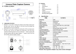
License Plate Camera
CLPR66B4B
Installation Precautions
1. Avoid installing camera where there are frequent vibrations or shocks.
2. Please keep the glass in front of the camera clean. Do not touch it directly.
Use a soft cloth with alcohol to wipe glass if necessary.
3. The available IR range of this camera is shown in the specification.
Please be sure to place the camera within the specified range.
3. In order to prevent damage to the camera, please do not loosen any screws or
covers unless modifying settings.
4. Please do not operate camera beyond conditions listed in the specification.
Use 12V DC regulated power supply to avoid damaging camera.
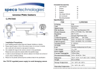
Included Accessories
User Manual
Screws
Anchors
x1
x4
x4
Mounting Template
Hex shape Wrench
DC Connector
x1
x1
x1
IP Rating
Type
Signal System
Pick Up Device
Picture Elements
Resolution
Number of LEDs
Min Illumination
Vertical Frequency
Horizontal Frequency
Clock Frequency
Scanning System
S/N Ratio
Electronic Shutter
Lens
White Balance
Back Light
Auto Gain Control
GAMMA
Video Out-put
Power Supply
Current Consumption
IR Range
Dimension
Weight
Storage Temperature
Operating Temperature
CLPR66B4B
IP66
Monochrome
NTSC/PAL
1/3" Sony Color High Resolution CCD
NTSC: 811H×508V; PAL: 795H×596V
550 TV Lines
80 IR LED
0 Lux
NTSC: 60Hz;
PAL: 50Hz
NTSC: 15.734KHz; PAL:15.625KHz
NTSC: 28.636MHz; PAL:28.375MHz
2:1 Interlace
≥50dB
NTSC: 1/60-1/100,000s; PAL: 1/50-1/100,000s
9-22mm Varifocal Auto Iris IR Lens
AUTO Tracking
ON
ON
0.45
1Vp-p,75Ω
DC12V ± 10%
200mA (Max)
6.56 ft – 49.18ft (2m – 15m) (Outdoor)
12.80” × 7.72” × 4.88” (325×196×124mm)
67.72oz (1920g)
-22 140°F (-30 60°C)
-22 104°F (-30 40°C)
~
~
~
~
We reserve the right to modify product design and specification without notice and without incurring any obligation
Changing IR Settings
If you want to change the IR settings, please remove the circular external
controls cover located on the bottom of the camera.
There are two Resistors with phillips head knobs, refer to the image below.
Resistor A: Controls the intensity of the IR LEDs
Turning (Clockwise) will decrease intensity
Turning (Counter-Clockwise) will increase intensity
Resistor B: Controls the lux threshold needed for triggering the IR LEDs
Turning (Clockwise) will increase lux threshold
Turning (Counter-Clockwise) will decrease lux threshold
Refer to the diagram below for optimum viewing angle.