1
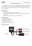
GA410 Pro Tail Lock Gyro Instruction Manual V1.1 GA410Pro Gyro Instruction Manual This series of ASSAN gyro come in models of GA4XX,GA5XX,GA6XX etc. This is the manual for GA410Pro. GA410Pro, is a new dual-gain tail lock gyro, with high performance product specially designed for 3D model helicopters by ASSAN, it’s has a lot advanced features such as easy handling and installation, stability in tail lock. FEATURES Sensor: Quartz vibration sensor Control system: AVCS(Angular Vector Control System) Dual-Gain System: tail lock mode / normal mode DS Swtich: Digital servo/Analogy servo choice. DIR function: Use the reverse switch on the gyro to set the output direction. Control LIMIT function: Use the travel rotary knob on the gyro to set the servo traveling range. Delay Trimmer: Rudder control singal operation trimmer. SPECIFICATIONS 1. Operating voltage: DC 3.3 ~ 9.0V 2. Operating current: 7mA 3. Operation temperature: -5℃ to 60℃ 4. Dimension: 27 X 27 X 20 mm 5. Weight: 15g FUNCTION 1. DS SWITCH: The ON position is for high speed signal Digital servo only 2. DIR SWITCH: It’s the reverse swtich,set the direction of output. 1/5 GA410 Pro Tail Lock Gyro Instruction Manual V1.1 3. LED Indicator: indicates the work mode of your gyro. (1) Light-on: the gyro is working as tail lock mode (2) Light-off: the gyro is working as normal mode (3) Blinking quickly: while power on in normal mode, the gyro can not initialize successfully. To solve this problem, turn the gain switch of transmitter to lock mode, then restart the receiver. (4) Blinking slowly: no signal received from receiver (5) Blinking twice: the center point of the tail servo has deviated, please reset. 4. DELAY: Rudder control singal operation trimmer.Conversely, to stop hunting,characteristics can be improved by ajusting the delay. When the trimmer is turned clock wise,the delay increase. For fast digital servo, the delay trimmer normal at “0”. 5. LIMIT: Travel rotary knob, set the servo traveling range.When the trimmer turned clock wire, the servo operating angle increases. 6. Gain Change Channel Connector: connect to the receiver gain channel output CH5(FUTABA) or AUX2\ AUX 3(JR).The gain of the gyro and the work mode can be set by this channel. 7. Rudder Channel Connector: connect to the receiver rudder channel output CH4(FUTABA) or RUDD(JR). 8. Tail Servo Connector: connect to the tail servo. INSTALLATION 1. Use the supplied double-side tape to securely adhere the gyro, the bottom face of the gyro should be perpendicular to the main rotor shaft, otherwise it may be disturbed by pitch or roll direction movement. If you use GA410Pro on electric helicopter, make sure the distance between the gyro and motor is more than 10cm. Don not fix the gyro near the vent or heat source, to avoid the possible disturbance. 2/5 GA410 Pro Tail Lock Gyro Instruction Manual V1.1 2. Connection list: (gain connector should be use with the transmitter with gain function) Transmitter type GA410’s 3Pin Rudder channel GA410’s Gain change channel connector to receiver connector to receiver JR,PPM/SPCM (and models under 9X) "CH4" (RUDD) "AUX2" FB(all the 1024 series model),JR 12X "CH4" (RUDD) "CH 5" JR 10X "CH4" (RUDD) "AUX3" 3. DS Swtich: after you choice your tail servo, please remember set the DS Switch to the corrected position. Pay attention, if you use Analogy servo,and you forgot the put the DS Swtich to OFF position,that will maybe burn your servo when power on. 4. To use your gyro (1) Turn on the power of your transmitter. (2) Set tail lock mode on your transmitter. (3) Turn on the power of your receiver, do not move the gyro and airframe for about 7 second until the LED on gyro turn red, so as to ensure the center point of the tail servo is set rightly. 5. Reset the center point of the tail servo. Quickly switch the gain setting on transmitter between tail lock mode and unlock mode for at least twice, then stop at tail lock mode. It requires the transmitter has two-section-gain switch function. 6. Check the output direction of gyro (very important!) Make sure the power of engine has been cut off. Take up the helicopter, turn the head of the model to the left, observe the moving direction of the tail servo, if the direction is the same as the movement while you pushing the transmitter’s rudder stick to the right, it means the reverse switch on your gyro is at the correct position. If not, please pull the reverse switch to another position. Caution: Incorrect setting of reverse switch would lead to your helicopter’s rotation in high speed while take-off! Please make sure the reverse switch on your gyro is at the correct position! FLY SETTING In order to get a high performance flight, you have to pay attention to the adjustment of the gyro and helicopter. The following steps are very important: 1. Adjust the appropriate pitch for main rotor wings Usually the maximal thread pitch valve is 9-12 degrees, each model has its own optimal value. 2. Choice of tail servo Strong torque and high response speed is the best choice. Strong torque ensures the high response speed. It is suggested that the torque force of the servo used on level 450 should be at least 1.2kg/cm, while the speed should be at least 0.13sec/60 degrees. The best choice is to use digital servos, the faster the servo is, the better performance you will get. 3. Mechanical Check (1) Strap Check Please replace the old strap. Tightness of the strap should be adjusted as needed, too tight strap will cost power, and slack one will limit the performance of gyro. It may lead to the rotation of helicopter when you increase the throttling quickly. 3/5 GA410 Pro Tail Lock Gyro Instruction Manual V1.1 (2) Pinions on the strap. Pinion is easy to slip, which will unlock the tail. (3) Check the tail shaft. No shake is allowed between tail shaft and tail case. The rotate speed of tail shaft is fourfold to the speed of main shaft. A tail axletree with any gap should be replaced immediately, as the axial gap inflects the thread pitch, which can affect the stabilization of tail lock directly. To solve the problem, install gaskets or replace tail gears. (4) Tail rotor nip check Been used for a period of time, the gap of tail rotor nip will get wide. So the fix screw on the nip needs to be checked regularly! The harm to person caused by shoot of tail wings maybe more dangerous than shoot of main wings. (5) Tail rotor Check Balance check and symmetry check should be performed to ensure the stabilization of flight. (6) Tail Servo Check Tail servo should be installed on tail tube firmly, damping rubber ring effect the rigidity of the structure, which should be installed selectively. (7)Check the rudder servo bar linkage The rudder servo bar linkage is an important drive part, but often is neglected, and we should choose a good rigidity bar. We should adjust the position of tail servo to make the bar parallel to the tail tube, and locked by stabilizer is not allowed. Before connect the bar to tail servo, try the bar with your hand to make sure the bar linkage work smoothly. After connecting the bar to the servo, twist the tail wing to observe the gap of tail rotor nip. Try to reduce the gap as small as you can. FINE ADJUSTMENTS 1. Before connection of the gyro and servo, the tail servo should be power on to let the rocker go back to the center point. 2. The gain need to be set as the GA410Pro has been installed. Normally, the gain value depends on the rotate speed of main shaft and the response speed of tail servo, the faster the response is, the higher gain can be set. But at the beginning of setting, we should switch the transmitter to the unlock mode (normal mode). 3. Ground test Put your helicopter on the horizontal ground with the tail facing to yourself(keep a safe distance) , turn the power on to finish the self-test (during self-test, don’t try to move the helicopter). Observe the rocker of tail servo, then adjust or change the rocker, to make it vertical to the servo. Go on to adjust the length of the connection bar, and avoid using the sub trim or inching switch to set the center point. Tail gliding block The tail gliding block should be adjusted to the center of the tail shaft, preferably leaning to the direction as you push the rudder to the right. Then push the rudder stick to the rightmost position, the gliding block should go to the side of the extreme position. While push the rudder stick to the leftmost position, the gliding block could not at the extreme position. The traveling range can be adjusted by the travel rotary knob. The next step is to try the throttling a little to see if the tail will turn to one side. If it is, adjust the length of connect bar or the position of tail servo to compensate. While the helicopter go on rising to 4/5 GA410 Pro Tail Lock Gyro Instruction Manual V1.1 keep hovering, the tail should not turn to each side too. (Beginners should get help from experienced users on this) 4. Then set the gain value to about 60%, and push the throttling to let your helicopter go up. As the helicopter hover steadily, push the throttling quickly, to control your helicopter rise rapidly. If the tail shakes, it means the gain value is too high. While if the tail turn to any side, it means the value is too low. Fine-tune the gain value to let the helicopter up and down quickly without turning. Congratulations! Your helicopter now is good to go! Now you can enjoy 3D flight! Have fun!! ASSAN ELECTRONIC CONTROL TECHNIC CO.,LTD 5/5