1
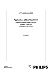
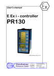
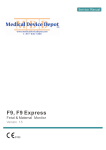
MPPT-10
Solar Charge Controller with
Maximum Power Point Tracking
Installation & Operation Manual
www.biall.com.pl
Content
1. Safety Instructions......................................................................................... 3
2. MPPT Controller Instructions......................................................................3
2.1 Overview....................................................................................................3
2.2 Structure....................................................................................................4
2.3 Functions.................................................................................................. 4
2.4 MPPT technology Instructions............................................................6
3. PV System Planning Reference.................................................................. 8
3.1 System Voltage........................................................................................ 8
3.2 Solar Modules Configuration...............................................................8
3.3 Wire Sizing................................................................................................ 9
3.4 Over Current Protection......................................................................10
3.5 Lightning Protection............................................................................ 10
3.6 Grounding............................................................................................... 11
3.7 System Expansion................................................................................11
4. Installation...................................................................................................... 11
4.1 Dimensions............................................................................................. 11
4.2 Connecting Diagram............................................................................ 12
4.3 Wiring....................................................................................................... 12
4.4 Installation Process............................................................................. 13
5. Operation Instructions................................................................................ 13
5.1 Button Function.................................................................................... 13
5.2 LED Displays..........................................................................................14
5.3 System Voltage Indication..................................................................14
6. Faults and Remedies................................................................................... 14
6.1 Protection Remedies........................................................................... 15
6.2 Common Faults and Remedies........................................................ 16
7. Technical Data............................................................................................... 17
8. Quality Assurance........................................................................................ 18
1
www.biall.com.pl
Dear Consumer:
Thank you very much for using our product! We will offer you the
permanent and reliable service for your solar system!
The manual gives important recommendations for installing and
using the MPPT controller. Please read the manual carefully and
thoroughly before using this product.
2
www.biall.com.pl
1. Safety Instructions
(1) The controller is only designed to be connected to the off-grid solar
system. It offers the management of charging and discharging for the
lead-acid battery of flooded, gel and AGM chemistries from 12V to 24V
nominal only. Do not connect this controller to other system, such as
mains supply and windmill generator.
(2) The controller is intended for indoor use only. Protect it from direct
sunlight and place it in a dry environment.
(3) Batteries generate explosive gases during normal operation. It is
important never allow a spark or flame in vicinity of battery.
(4) Be sure to always keep children away from batteries and acid!
(5) Do not disassemble the MPPT controller, it does not have any
user-serviceable parts.
(6) The controller warms up during normal operation. Do not touch the
heatsink at the bottom of the controller.
Note: It is important that the battery is fully charged frequently (at least
monthly). Otherwise the battery will be permanently damaged.
2. MPPT Controller Instructions
2.1 Overview
MPPT-10 solar charge controller is multi-stage Maximum Power Point
Tracking (MPPT) photovoltaic battery charge controller with our own
technology. It’s main topology adopts in Buck conversion circuit, and uses
MCU to adjust the solar panels working point intelligently in order to make the
solar panels output its maximum power. When the circumstances change, the
working point of solar panels deviate from the maximum power point, MCU will
adjust the solar panels working point based on MPPT calculation to make the
solar panels back to the maximum power point again(refer to Chapter 2.4
about MPPT technology introduction). Compared with PWM controller, MPPT
controller can increase the output power of solar panels by 5%~30%. The
output power increasing proportion is affected by the factors such as solar
panels property, humidity and light intensity. The controller uses wall-mount
installing (refer to Chapter 4.1). Connecting terminal makes the wiring area
bigger and wiring loss less.
3
www.biall.com.pl
2.2 Structure
①
②
③
④
⑤
1
Bottom Heatsink
2
Indicators and Reset key
3
Solar Terminal Block
4
Battery Terminal Block
5
Load Terminal Block
Figure 2-1: Controller Structure Diagram
2.3 Functions
(1) Maximum Power Point Tracking technology
The controller uses Buck conversion circuit and MCU technology to track
the maximum power point to implement the maximum output power of solar
panels in different illumination intensity and temperature. The MPPT
algorithm increases efficiency of your PV system and decreases the
quantity of solar panels.
(2) Multi-stage Charge Control
The starting charging voltage of battery is different, the controller will use
the different charging strategies to finalize the charging process. When
starting charging voltage of battery is lower than 12.4V (for 12V battery),
battery will go through three stages as Bulk, Absorption and Float charging.
When starting charging voltage of battery is higher than 12.4V (for 12V
battery), battery will go through two stages as Bulk and Float charging.
Bulk Charge:
The controller charges the battery by its maximum output current. It is at
maximum power point tracking state at this phrase.
Absorption Charge:
The controller begins to limit the charging current to make the battery
voltage fixed at a settled absorption voltage (this voltage has temperature
compensation) for 2 hours. It increases the charging saturation level of
4
www.biall.com.pl
battery and prevents battery from leaking gas, and this can increase the
lifetime of battery.
Float Charge:
The battery is at saturation state, and the controller charges the battery at a
trickle current to make the battery voltage fixed at the settled float charging
voltage (this voltage has temperature compensation).
U
Bulk
12.0V
2h
U
Absorption
Float
t
Figure 2-2: Three-stage Charge
Bulk
12.4V
Float
t
Figure 2-3: Two-stage Charge
(3) Charge Voltage Temperature-compensated
The controller will compensate the Float charging voltage and Absorption
charging voltage by -4mV/Cell/°C based on the current battery
temperature.
For 12V battery, the compensated voltage U=(t-25)*6*(-0.004)V
For 24V battery, the compensated voltage U=(t-25)*12*(-0.004)V
(4) Discharge Control
The controller monitors the battery voltage all the time. The load will be
switched off when the voltage less than the Low Voltage Disconnect (LVD)
point, and it won’t be switched on until the voltage more than the Low
Voltage Reconnect (LVR) point.
(5) Protection against Reverse Connected Battery
Connecting the battery to the controller by reversed polarity (under the
circumstances of solar panels disconnected) will not damage the controller.
The controller will work normally after connecting with correct polarity.
(6) Protection against Reverse Connected Solar Modules
Connecting the solar modules with the controller by reserved connection
will not damage the controller. The controller will work normally after
connecting with correct polarity.
(7) Reverse Current Protection
The controller prevents reverse current from flowing into the solar modules
5
www.biall.com.pl
at night. An additional reverse current diode is not required.
(8) Overtemperature Protection
If the temperature inside the controller becomes too high, then the
controller will stop charging to the battery, and it will restart charging the
battery again when the temperature decreases to a certain value.
(9) PV Overvoltage Protection
If the input voltage of solar panels exceeds the maximum voltage permitted
by the controller, it will enter into protection state automatically and stop
charging. When the input voltage recovers to the normal range, the
controller will start charging again.
(10) Current-limited for Excessive Charging Current
If the permissible charge current is exceed, the controller will deviate from
the maximum power point to limit the output current to prevent the
controller being damaged.
(11) Load Output Overload Protection
If the permissible load current is exceed, then the load output is switched
off. The overload current vs. duration shows as follows:
Rate of Current
Duration (s)
1.1Irate ≤I< 1.2Irate
120
1.2Irate ≤I< 1.5Irate
60
1.5Irate ≤I< 1.8Irate
10
I≥ 1.8Irate
0.2
Note: Irate=10A, nominal load current
The controller restarts the load every 3 minutes automatically, but the user
can also restart the load by the Restart key.
2.4 MPPT technology Instructions
Solar panels are nonlinear materials, and the output power is mainly
affected by illumination intensity, solar panels temperature and load
impedance. When the illumination intensity and solar panels temperature are
fixed, the output power of solar panels is only affected by load impedance.
Different load impedance will make the solar panels work at different point and
put out the different power. The following figure will mark the four working
points A, B, C, D, and the working point features as follows:
6
www.biall.com.pl
Working point D:
Output voltage is 22.3V, output power is 0W. This point is the open circuit
point of solar panels.
Working point C:
Output voltage is 0V, output power is 0W. This point is the short circuit
working point of solar panels.
Working point A:
Output voltage is 13V, output power is 74W. This working point is the state
when using normal controller, and the solar panels voltage is clamped to
13V by battery.
Working point B:
Output voltage is 17.6V, output power is 92W. This point is the state when
using MPPT controller. Because of using power conversion technology, the
solar panels voltage is not clamped by battery and still works at maximum
power point.
Compare working point A & B, it is easy to find using MPPT controller can
increase the using efficiency of solar panels. Compared to normal controller,
MPPT controller can generate more power.
Figure 2-4: Voltage-Current Curve
7
www.biall.com.pl
Figure 2-5: Voltage-Power Curve
3. PV System Planning Reference
3.1 System Voltage
The common system voltage of solar system has 3 types: 12V, 24V and 48V.
The higher the system voltage, the more power the system can handle. In
reality application, user should consider the load power, and the voltage scope
permitted by load, and then confirms which system voltage you should use.
The power range for each system voltage is as follows:
System Voltage
Recommended Power Range
12V
<800W
24V
<2000W
48V
<6000W
Table 3-1: System voltage vs. Power range
3.2 Solar Modules Configuration
MPPT-10 controller can be connected with Single Crystalline Silicon solar
panels and also Thin-film solar panels. When configuring the system, make
sure the open circuit voltage of solar panels array is not higher than the
maximum voltage permitted by the controller. Table 3-2 introduces the models
of Single Crystalline Silicon solar panels and Thin-film solar panels and their
parameters. Table 3-3 shows the configuration solution for 12V, 24V and 48V
system for solar panels.
8
www.biall.com.pl
Code
Category
Pmax
Voc
Isc
Vpmax
Ipmax
140W-01
Single
Crystallin
e Silicon
Module
140W
22.4V
8.33A
17.6V
7.95A
14W-0W-02
Thin-film
Module
140W
29.0V
7.12A
23.0V
6.52A
190W-01
Single
Crystallin
e Silicon
Module
190W
45.2V
5.65A
36.6V
5.2A
130W-01
Thin-film
Module
130W
60.4V
3.41A
46.1V
2.82A
The above parameters are for condition of 25°C, AM1.5 spectrum, and
1000W/m2 illumination intensity.
Table 3-2: Solar Panels Model and Parameters
Code
For 12V System
For 24V System
For 48V System
140W-01
N in parallel
two in series,
N in parallel
four in series,
N in parallel
140W-02
N in parallel
two in series,
N in parallel
four in series,
N in parallel
190W-01
N in parallel
N in parallel
two in series,
N in parallel
130W-01
N in parallel
N in parallel
two in series,
N in parallel
N means the quantity number required by the output current.
Table 3-3: Solar Panels Model and System Configuration Solution
3.3 Wire Sizing
The maximum input and output current of MPPT-10 is 10A. To ensure the
cable temperature does not exceed the safety range, the copper cable’s area
must be at least 2.5mm2. In reality application, user can choose the
appropriate cables according to the system voltage, permitted cable
9
www.biall.com.pl
temperature, cable voltage drop and also cable material. We suggest
customer to control the maximum battery voltage loss under 1.5%, and control
the maximum voltage loss of solar panels under 2.5%.
The following is the cable length between controller and battery, and the
suggested copper cables:
Cable
Cable Size
Cable Size
Length
in mm2
in AWG
1m
2.5mm2
2m
4m
Voltage Loss
at 10A
(a pair)
Battery Voltage Loss
12V
24V
48V
#13 AWG
0.14V
1.2%
0.60%
0.30%
4mm
2
#11 AWG
0.18V
1.5%
0.75%
0.38%
6mm
2
#9 AWG
0.24V
2.0%
1.0%
0.50%
Table 3-4: Cable Length & Cable Voltage Drop
The following is the cable length between solar panels and controller, and
also the suggested copper cables:
Cable
Length
2m
4m
8m
Cable
Size in
2
mm
4mm
2
6mm
2
2
10mm
Cable Size
in AWG
Solar Panels
Voltage Loss
Voltage Loss
at 10A
(a pair)
17V
34V
68V
#11 AWG
0.18V
1.1%
0.53%
0.26%
#9 AWG
0.24V
1.4%
0.71%
0.35%
#7 AWG
0.29V
1.7%
0.86%
0.43%
Table 3-5: Cable Length & Cable Voltage Drop
3.4 Over Current Protection
The electrical equipment used in power circuit must be equipped with over
current and short-circuit protection devices, and there is no exception for
MPPT-10 controller. The controller adopts in the design of common positive
pole inside. We suggest users to install over-current breaker or fuse on the
negative loop of solar panels input, and also the negative loop of battery output.
The capacity of over-current breaker or fuse is 1.25 times of the rated current.
3.5 Lightning Protection
It is the same as other electrical devices that MPPT-20 controller will be
damaged by lightning. The controller has limited surge absorption capacity.
We strongly suggest users to install lightning surge absorption devices to
increase the reliability of the system.
10
www.biall.com.pl
3.6 Grounding
Use 4 mm2 yellow and green cable to connect any of the positive terminal of
the controller to the ground bus of the system. This can decrease the
electromagnetic interference in a certain value.
3.7 System Expansion
If you want to deploy a bigger system, you can expand the system by
paralleling several sets of the same controller. More controllers can share with
one battery group, but each controller must be connected with the independent
solar panels array and the independent load. (Please contact the local
distributor for further information.)
4. Installation
1. Protect the controller from direct sunlight or other source of
heat.
2. Place the controller in a dry environment.
3. A free space of at least 15cm on all side of the controller
must be provided.
4. Mount the controller as close as possible to the batteries.
4.1 Dimensions
Figure 4-1: Dimensions (Unit: mm)
11
www.biall.com.pl
Mounting hole pitch: 60mm*178mm
Mounting hole diameter: Ф5mm
Height*Width*Thickness: 92.5mm*188mm*55.3mm
Connecting terminals:
Maximum 6mm²
4.2 Connecting Diagram
Temperature Sensor
Fuse
③
①
②
Figure 4-2: Connecting Diagram
4.3 Wiring
A、Choose the appropriate cables requested as Chapter 3. Prepare 4 sets
of M5 screws (used to fix the controller on the wall or other vertical
plane).
B、Prepare cutting pliers, cross screwdriver and multi-meter, etc.
12
www.biall.com.pl
4.4 Installation Process
Note: Please switch off the breakers of battery, solar
panels array before installing the controller. Do not touch
the positive and negative pole of solar panels or battery
at the same time when installing, otherwise you have the
risk of electrical shock.
A. Mount the controller on the wall and fasten the screws.
B. Check whether the battery voltage and solar panels array voltage is
within the requested range.
C. Switch off the over-current breaker or fuse of the battery, solar panels
array and load.
D. Wiring.
(1) Connect the battery with the battery terminal on the controller by
cables and fasten the screws.
(2) Connect the load with the load terminal on the controller by cables and
fasten the screws.
(3) Connect the solar panels array with the solar panel terminal on
controller by cables and fasten the screws.
E. Switch on the breaker or fuse of the battery, then the 3 indicators indicate
the system status. Switch on the breaker or fuse of the load. (more
information about the indicators see Chapter 5.2 and 5.3)
F. Switch on the breaker or fuse of the battery, then the controller starts to
charge the battery.
5. Operation Instructions
5.1 Button Function
There is only one concealed button on the controller, which used to restart
the load when the controller is in overload protection state. The second
function of the button is to control the load. Press the button and hold about 3
seconds, then the load will be switched off. This can also switch on the load.
13
www.biall.com.pl
5.2 LED Displays
LED
Meaning
Status
Solar
(Red)
PV Voltage Low
off
MPPT Charge
illuminates
Absorption Charge
T=2s
Float Charge
T=1s
PV Overvoltage Protection
Battery
(Green)
T=0.5s
Battery Disconnect
off
Normal Operation
illuminates
Undervoltage Protection
T=2s
Overvoltage Protection
T=1s
Overtemperature Protection
Load
(Red)
T=0.5s
Load Off
off
Load On
illuminates
Heatsink Temperature Sensor Error
Overload Protection
Load Short-circuit Protection
T=2.2s
T=1s
T=0.5s
5.3 System Voltage Indication
The MPPT-10 controller adjusts itself to 12V or 24V system voltage
automatically. The system type indicates by the green led when the controller
startup every time. Details show as follows:
Figure 5-3: System Voltage Indication Diagram
6. Faults and Remedies
14
www.biall.com.pl
6.1 Protection Remedies
Fault
Battery
voltage
too low
Battery
voltage
too high
Phenomenon
Load off
Charging on
Cause / Remedy
Check the battery voltage and manually
recharge the battery if necessary. Loads
directly connected to the battery can cause
deep discharge.
Load off
Charging off
Check installation. Check the battery
voltage and check any additional charging
sources if present.
Load on
Charging off
Check the PV system configuration. The PV
open circuit voltage increases while the
ambient temperature decreases.
Excessive
load current
Load off
Charging on
Reduce the load current at the load output.
The load may cause current peaks.
Load output
short circuit
Load off
Charging on
Rectify short circuit.
reconnect the load.
PV voltage
too high
Controller
inside
temperature
too high
Inside
temperature
sensor
error
Self-test
error
Load on
Charging off
Load on
Charging on
Load,
charging
indefinite
Disconnect
and
Allow the controller to cool down. Check for
possible causes of overheating (mounting
location, other heat sources). Possibly
reduce the charge current. Make sure the
controller is adequately ventilated.
Disconnect the load, solar modules and
battery. Re-install the controller. If the error
recurs, then please contact your specialist
dealer.
Disconnect the load, solar modules and
battery. Re-install the controller. If the error
recurs, then please contact your specialist
dealer.
15
www.biall.com.pl
6.2 Common Faults and Remedies
Phenomenon
Cause
Remedy
The battery is
connected to the
controller with the
wrong polarity. The
fuse burns out.
Check the fuse.
Disconnect the battery and reconnect
it to the controller with the correct
polarity.
Battery
overvoltage
protection
when startup
The controller
adjusts to the
wrong system
voltage.
Disconnect the load, solar modules
and battery. Waiting for about 10
seconds and then re-install the
controller.
Stay in direct
charging
mode
The PV MPP
voltage too low.
It’s normal. If possible you can
re-configure the PV system to enlarge
the PV open circuit voltage.
LEDs no
indication
16
www.biall.com.pl
7. Technical Data
Model
Input
Output
Other
MPPT-10
Maximum PV voltage
≤70V
MPPT voltage range
12V~70V (12V)
24V~70V (24V)
System voltage
12V (24V)
Maximum battery voltage
16V (32V)
Maximum charging current
10A
Maximum load current
10A
Own consumption
≤15mA
Charging control mode
3-stage (Bulk, Absorption, Float)
Float charge
13.8V (27.6V)
Absorption charge
14.4V (28.8V), for 2 hours
Load disconnection (LVD)
11.5V (23.0V)
Load reconnection (LVR)
12.6V (25.2V)
Temperature
compensation
-4mV/ cell/ °C
Battery type
Lead acid (GEL, AGM, Flooded)
Maximum efficiency
97%
Human interface
LEDs, button
Cooling style
Passive cooling
Maximum wire size
6 mm2
Ambient temperature
range
-10 to +50 °C
Storage temperature
range
-30 to +80 °C
Humidity
0 to 90%, no condensation
Dimensions
92.5 x 188 x 55.3 mm
Weight
0.46 Kg
Grounding
Positive grounding
Degree of protection
IP32
Note: Technical data at 25 °C / 77 °F
17
www.biall.com.pl