1
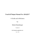
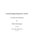
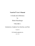
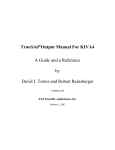
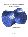
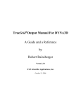
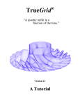
Parametric Finite Element Modeling Across Many Simulation Codes 1
Robert Rainsberger
XYZ Scientific Applications, Inc.
1324 Concannon Blvd.
Livermore, CA 94550
[email protected]
Abstract
It is shown, with TrueGrid®, that a finite element model can be created in a preprocessor and
exported to many finite element codes such that the model is identical for each finite element
code. Parameters, expressions, and conditional statements in a template input file simplify
smooth or discrete variations in the generation of the mesh, material properties, element
properties, loads, and constraints.
Keywords: ABAQUS™; ANSYS®; applied mechanics; computational fluid dynamics; computer
models; finite element analysis; finite element modeling; fluid mechanics; hexahedral; LSDYNA™; mathematical modeling; mesh generation; multi-block structured; NASTRAN®;
parametric; parametric finite element modeling; projection; quadrilateral; simulation; solid
mechanics.
Introduction
The finite element method (FEM) is an essential tool in the design and understanding of complex
structures. A typical finite element session starts with a simplified model to make quick and dirty
simulations to gain basic insights into the structure. These insights will lead to refinements in
mesh density and detail. This numerical testing of the structure may require numerous
simulations with different loads and boundary conditions. There may be significant changes
during the evolution of the design of a complex structure. Altogether, many finite element
experiments will be required. A preprocessor to the FEM should make it easy to evolve and
modify the model.
The verification and validation of a finite element computer model places additional
requirements on the preprocessor. The identical model must be generated for each code being
tested and compared in the verification and validation procedure. Key features of the model need
to be isolated so that their properties can be varied independently. This is necessary so that a
variance in the measurement of the physical model can be propagated to the numerical model
and the results of the simulation. This may also be useful in determining if a linear simulation is
stable, meaning a small change in the numerical model should produce small variations in the
results of the simulation. Some of the features to vary are material properties, geometric shapes,
and mesh density. Ideally, it should be easy to vary these features smoothly or in a discrete
manner. It should also be possible to vary features using a random perturbation. A hexahedral
1
Presented at NIST 2004 Workshop on Verification & Validation of Computer Models of Highconsequence Engineering Systems, Nov. 8-9, 2004.
mesh for a solid object and a quadrilateral mesh for a shell structure are considered, by many, to
be the ideal elements for finite element analysis [2]. This is particularly true for nonlinear
analysis. When these types of elements form block structures, the meshes tend to be nearly
orthogonal. These types of meshes usually reduce the order of the numerical error in the
simulation [9] [10]. Such a mesh is desirable when comparing results from many simulation
codes. A poor quality mesh in the simulation will cause confusion when comparing the results of
experiments using many simulation codes. On the other hand, a lower quality mesh may be
needed to test the range of performance in the simulation codes. Thus it is necessary that a
preprocessor have the flexibility to vary the mesh quality.
It is also important that small changes to geometry cause only small changes in the mesh density.
If a small change in the geometry were to make a radical change in the mesh, then any variation
in the simulation results could be the results of the radical change in the mesh. This is a strong
argument for multi-block structured meshes where the mesh topology is prescribed. It is
potentially a problem with automatic mesh generators that can undergo a radical change in the
mesh topology when a small change is made to the geometry.
TrueGrid® [1] is a commercial preprocessor for many FEA and CFD simulation codes. It is used
to generate high quality, multi-block, linear or quadratic, hexahedral solid, quadrilateral shell or
plate, and beam or truss elements. It can also generate prisms, tetrahedrons, and triangles in very
small numbers, as required for a good mesh.
This paper demonstrates the building and exporting of several simple TrueGrid® models for
nonlinear static analysis to be performed by ABAQUS™ [5] [6], ANSYS® [7], LS-DYNA™ [8],
and NASTRAN® 2 [4]. Most commands used below to generate these models are not targeted for
a particular simulation code because most simulation codes do non-linear static simulations in a
similar fashion. Even in a dynamic simulation, the differences in the commands to TrueGrid®
for the different simulation codes are quite limited. Each of these simulation codes offers a
different set of multi-physics capabilities and, consequently, a different set of loads that can be
applied. The different loads will not be discussed in this paper. The remaining differences are
categorized as follows:
1. Material models, equation of state, quadrature, and element types - each simulation code has a
different set of material types. They all include an isotropic plastic material. Each code defines
the yield curve differently. The element type and equation of state are coupled to the material
model and are selected at the same time the material properties are selected. Only the hex solid
or the quad shell type is selected. If a prism, pyramid, tet, or triangle is formed during the
element generation phase, the appropriate element type for that element is automatically
selected. The commands that define material properties end with mats. The mate, mt, and mti
commands are used to associate a group of elements with a material model.
2
TrueGrid is a Registered Trademark of XYZ Scientific Applications, Inc., ABAQUS is a Trademark of
ABAQUS, Inc., ANSYS is a Registered Trademark of SAS IP, Inc., LS-DYNA is a Trademark of Livermore
Software Technology Corp., NASTRAN is a Registered Trademark of NASA.
2. Analysis options - initial time step, number of iterations, output and data base options,
solution method, case selection, and other global controls fall in this category. The commands
that specify the analysis options end with opts.
3. Element cross sectional properties - shell cross sectional properties are defined within the
material model definition. Variable shell thicknesses are not supported by all simulation codes
and must be avoided when making validation and verification comparisons. Beam cross section
properties vary greatly and are defined with the bsd command. These beam cross sectional
properties are then referenced within the material definition or the commands that generate the
beams such as ibm, jbm, kbm, and bm. A limited orthotropy feature is handled within the
material model. It is this author’s wish that beam cross section properties be standardized. The
benefits would include translation of the model from one simulation code format to another and
verification and validation of finite element models. With a standard in beam cross sections, one
could have greater confidence in the comparison of results from many simulation codes. Perhaps
the beam cross sectional properties defined in the IGES [3] standard can be used as a standard. If
each simulation code supported at least these features, then translations and comparisons could
be assured.
4. Contact surfaces - methods used in the
simulation codes vary greatly and continue to
evolve. The sid command is used to select the
properties of the contact surfaces. This author is
not aware of any comparative studies of the
contact surfaces available in these simulation
codes. An advanced verification and validation of
finite element computer modeling should include
contact surfaces. One common characteristic of
contact surfaces is a loss of accuracy. In particular,
tied contacts used to glue two dissimilar faces of a
material interface are unwarranted in TrueGrid®.
The interface between two parts of the mesh can
always be made to match. The block boundary
(bb) command is used to glue two similar parts.
The transitional block boundary (trbb) command
Example of a transition region between two blocks
will glue two dissimilar faces together using all
hex elements for solids and all quad elements when using shells by automatically generating a
transitional region at the interface. There are some limitations to the trbb command that are
easily met when the mesh topology is planned.
5. Springs, dampers, and point masses - material properties and degrees of freedom vary between
the simulation codes. If a model is to be run with these special element types, properties should
be selected that are available in all simulation codes. The spd command specifies the material
properties. The degrees of freedom are specified when the element is defined with, for example,
the spring command. Point mass properties are defined at the time these elements are
generated with, for example, the pm and npm commands.
In the examples below, text in the Courier font indicate input to TrueGrid®. Bold
Courier font indicates a keyword command. The c command starts a comment.
TrueGrid® accepts a batch file or runs interactively with menus and buttons. A session file is
generated to record both batch and interactively generated commands. This session file can be
used to reproduce the model in batch mode. Typically, the user creates a simple model
interactively and then modifies the session file with a text editor for subsequent reruns in batch
mode. The interrupt and resume commands can be useful when making incremental
changes, interactively, to the batch file.
Creating a Single Block Part
The block command creates a three dimensional rectangular mesh. The numbering of nodes in
each of the three directions is independent, starting with 1. This produces a three dimensional
array of nodes. Each node is uniquely identified by three indices. They are referred to as the i, j,
and k indices. For example, the command
block
1 5;
1 6;
1 7;
c
c
c
c
indices of a single block part
i-list
j-list
k-list
produces a grid with an i-index ranging from 1 to 5, a j-index ranging from1 to 6, and a k-index
ranging from 1 to 7. Each pair of numbers in the block command ends with a semi-colon and is
referred to as an index list. The semi-colon terminates each list. It is shown, in the next example,
that the block command can be used to create a part with many blocks. For this reason, the
syntax for the block command must allow for each index list to have arbitrary length. The
three dimensional space containing the i, j, and k indices is sometimes referred to as the
computational domain of the mesh.
The edges of this block are initially parallel to the coordinate axis and the faces are planar. The
remaining arguments of the block command assign x, y, and z-coordinates to the mesh. For
example,
2 5;
1.4 7;
2 7;
c x-coordinate list
c y-coordinate list
c z-coordinate list
completes the block command above. The first list of coordinates specifies the x-coordinate for
the 2 faces perpendicular to the x-axis. There must be one x-coordinate for each index in the iindex list. The same is required for the y-coordinates corresponding to the j-index list and the zcoordinates corresponding to the k-index list. Sometimes the three dimensional space containing
the x, y, and z-coordinates is referred to as the physical range of the mesh.
Creating a Multi-Block Part
The block command is generalized so that a single part can have any number of connected
blocks. The block command usually contains more blocks than are needed for a particular
problem. This is because it is usually easier to define an array of blocks and delete some of them
then it is to define each required block separately. For example,
para th .1;
block
1 13 17 31 35 47;
1 5 10 14;
1 25;
0 .28 .37 .63 .72 1;
0 .08 [.08+%th] [.16+%th];
0 .5;
c sample thickness parameter
c
c
c
c
c
c
i-index list
j-index list
k-index list
x-coordinate list
y-coordinate list
z-coordinate list
This part has 5 blocks in the i-direction, 3 blocks in the j-direction, and 1 block in the k-direction
in the computational domain. Each number in the i-index list specifies the end of one block and
the beginning of the next. The same is true about the j-index and k-index lists. The interfaces
between the blocks, located at the node numbers in the index lists, are referred to as partitions
and they are numbered by their sequence in the index list. The x, y, and z-coordinate lists
position the partitions in the i-, j-, and k-directions, respectively.
A few more commands will be introduced and added to this block command to build a simple
model of a sample material being drawn between two clamps.
Physical Mesh with 13 blocks of hex elements
Computation Mesh with 13 blocks
Starting with the block command above, all unneeded blocks are removed with a dei (delete)
command. For example, the command
dei 3 4; 1 2 0 3 4;1 2;
c delete 2 blocks
removes two blocks. Both blocks start at the 3rd partition and end in the 4th partition in the idirection. One block goes from the 1st to the 2nd partition in the j-direction. The second block
goes from the 3rd to the 4th partition in the j-direction. Note that the 0 in the j-index list is used to
indicate a gap and can be interpreted as the word “and”. Both blocks go from the 1st to the 2nd
partition in the k-direction.
Commands that end with i require three index lists. The three index lists are sometimes referred
to as an index progression.
De is an alternative form of the delete command. This command deletes one block. The
following accomplishes the same thing as the above dei command:
de 3 1 1 4 2 2
de 3 3 1 4 4 2
c delete first block
c delete second block
This type of command requires 6 numbers. They are:
starting i-partition number
starting j-partition number
starting k-partition number
ending i-partition number
ending j-partition number
ending k-partition number
These six numbers are sometimes referred to as a region. The region notation is an option
because of its simplicity. With large and complex models, this notation becomes tedious and
inefficient. Typically, a beginner chooses commands with a region notation and graduates to
commands with an index progression as they become sophisticated users. Large and complex
structures can be constructed using index progressions with a minimum number of commands.
The graphical user interface and, in particular, the computational window makes the selection of
an index progression relatively intuitive.
Parametric Nature of the Block Command
The block command is one of only two commands that specify the block structure or topology
of the part. The insprt command, to insert a partition, is the other command but is not detailed
in this paper. The block command is one of only two commands that specify the number of
nodes within each block of the part. The other is the mseq command that adds or removes
nodes. The insprt and mseq commands augment the block command so that the user can
change the mesh without having to go back and modify the block command. The mseq
command is also not discussed in further detail because it is available only as a convenience and
does not offer a fundamental capability.
If we ignore these two exceptional commands, the block command is the only command that
refers to the actual nodes in the mesh. All subsequent commands in the part refer to partition
numbers. Essentially, the numbers in the index progression and the region notation are numbered
parameters whose true values are specified in the block command. Thus the user can change
the number of nodes in the mesh by modifying the index lists in the block command. All other
commands will be automatically adjusted.
Moving Corners of the Mesh
Portions of the mesh, either a region or an index progression, can be moved as a rigid body using
the pb, mb, and mbi commands. The pb command assigns coordinates and the mb or mbi
commands modify the coordinates by adding a component. For example,
pb 3 1 1 4 1 2 y .08
mb 3 4 1 4 4 2 y -.08
c assign the y-coordinate
c decrease the y-coordinate
Final mesh after moving 8 corners
The tr command is a more general method of manipulating the mesh. These three commands
change the coordinates of the corners of the blocks. Then the edges, faces, and interior nodes are
interpolated. The graphical user interface can be used to create these commands with a click and
drag of the mouse to move the corners of the block. The arguments to these commands can then
be replaced with parametric algebraic expressions using a text editor to modify the session file.
Nodal Constraints
The b and bi commands assign nodal constraints. In the command below, the z-displacement is
constrained at the base of the clamps. For some simulation codes with case control, such as
ABAQUS™ and NASTRAN®, a set identifier or case control number (sid) should be assigned to
the constraint. Notice that this command ends in a semicolon indicating this command has many
options. Any of the degrees of freedom can be constrained by adding options to the list.
bi 1 3 0 4 6;1 2 0 3 4;-1;sid 1 dz 1 ;
Fixed Displacement
For historical reasons, many commands imposing loads require a load curve number, set
identified, or case control number. For example, the fd and fdi specify fixed displacements.
This identification number in the argument list is followed by an amplitude and a 3D
displacement vector.
fdi -1;1 2 0 3 4;1 2;1 1 -1 0 0
fdi -6;1 2 0 3 4;1 2;1 1 1 0 0
Material Assignment
Materials are identified with a positive number. The properties of the material are defined below.
All elements are assigned a material number. The default is 1. The mate command changes the
default. The mt and mti commands assign materials to different regions of the mesh. In the
draw model, the elements to be drawn are assigned material 1 and the clamp elements are
assigned material 2 by default.
mate 2
mt 1 2 1 6 3 2 1
Other Parametric Features
The para command defines parameters that can be used in place of any number. The %
character must precede the use of any parameter.
para k2 7 density 2.236 ;
c define k2 and density
Algebraic expressions can be inserted wherever a number is needed to complete a command.
The expression must be enclosed by the open and close square brackets. The syntax for operators
and intrinsic functions match FORTRAN with the following exceptions:
1. ^ and ** can be used for exponentiation
2. Trigonometric functions use degrees (not radians)
3. The norm function generates a random variable with a normal distribution
para k2 [3**2+1] density [sqrt(5)]; c define k2 and density
The intrinsic functions are int, nint, abs, mod, sign, max, min, sqrt, exp, log, log10,
sin, cos, tan, asin, acos, atan, atan2, sinh, cosh, rand, and norm. Additional
functions can be defined with the def command.
def function_name(a,b,c) = expression
The function can have many dummy arguments. The expression should be dependent on the
dummy arguments. Once defined, a function can be used in the same manner as the intrinsic
functions.
The if, elseif, else, endif conditional statement is also available with the same
properties as in FORTRAN. For example:
if(%density.gt.1.0)then
block 1 5;1 6;1 %k2;2 5;1.4 7;2 7;
else
block 1 5;1 6;1 [%k2*%density];2 5;1.4 7;2 7;
endif
The above commands issue a different block command depending on the density parameter. A
typical use of the conditional statement is to insert a new partition when the conditions warrant
it. For example:
if(%rad3-%rad1.gt.0.1)then
if(%i3-%i1.lt.6)then
mseq i [6+%i1-%i3] c add elements in the i-direction
endif
insprt 1 2 1 5
c insert a partition in the i-direction
endif
The include command will transfer the input stream to another file. After all the commands
are read from this file, the input stream is then returned to the original source. If the file is
parametric, then the include feature is similar to a subroutine call in a programming language.
For example:
c
c
c
c
c
rad is the radius of the
x0 is the x-component of
y0 is the y-component of
z0 is the z-component of
n is the node density of
sphere
the center of the sphere
the center of the sphere
the center of the sphere
the mesh
para rad 1.0 x0 0 y0 0 z0 0 n 10; c set parameters for sphere 1
include sphere c include the spherical part file
para rad 1.2 x0 2 y0 2 z0 2 n 12; c set parameters for sphere 2
include sphere c include the spherical part file
produces two spheres using the commands in an included file called sphere. The details of the
sphere file are left to the reader.
Code Specific Material Models and Analysis Options
Another important use of the if, elseif, else, and endif statements are now shown
with the material models for all the simulation codes mentioned above. The outtyp parameter
will be used to set the output format type so that only this parameter needs to be changed to
switch from one output option to any other. We adopt the following convention for the value of
outtyp:
c 1 means
c 2 means
c 3 means
c 4 means
para
output
output
output
output
outtyp
to
to
to
to
1;
ABAQUS
ANSYS
LS-DYNA
NASTRAN
In this example we will use the following material parameters including some isotropic plasticity
constants to define the same material model for all four simulation codes:
para
rho 7.0e-4
e 3.0e+7
pr .3
sigy 75000
et 1.0e+5;
c
c
c
c
c
density
Young’s Modulus
Poisson’s Ratio
yield stress
tangent modulus
There will actually be two material models. The first is for the material that will be deformed.
The second material will be used for the hardened metal clamps. Similar features are selected for
each simulation code. It is convenient to lump all of the code specific analysis options with the
code specific material commands.
para
ts .01
term .1;
c time step
c termination time
The material models and analysis options in each simulation code are quite different. Therefore,
the syntax of the commands to specify these properties in TrueGrid® is different for each
simulation code. With the aid of the graphical user interface, it is easy to create the same
material model for all four simulation codes. The graphical user interface produces the correct
syntax that is then recorded in the session file.
There is a pattern to these commands. A command is needed to select the output format. It is
usually the name of the simulation code. The commands are: abaqus, ansys, lsdyna
keyword, and nastran. The lsdyna command has an argument because older versions of
LS-DYNA™ allowed for a second format that is still available in TrueGrid®. The analysis
commands are abaqstep, ansyopts, lsdyopts, and nastopts. The ABAQUS™
analysis options command is different because it is needed for each step. The other simulation
codes option commands are usually issued only once. The material commands are abaqmats,
ansymats, lsdymats, and nastmats. Each use of these commands defines one material.
Both the analysis options and the material definitions can have many options activated and each
command is terminated with a semicolon.
After the commands to choose the output, material models, and analysis options have been
issued, the if, elseif, endif statements, the parameters, and comments can be added to
the session file with a text editor to produce:
if(%outtyp.eq.1)then
c ABAQUS specific
abaqus c selects the output format
abaqstep abstep 1 c STEP definition
static .0001 %ts %term ; c select static analysis
abcload blc 1 fd ; c include displacements load curve 1
abaqmats 1 c elastic-plastic material
aqeltyp C3D
aqdens %rho
aqelas
aqelis %e %pr ;;
aqplas %sigy [%sigy/%e];
[%sigy+(1-%sigy/%e)*%et] 1;;;
abaqmats 2 c same as first material but stiffer
aqeltyp C3D
aqdens %rho
aqelas
aqelis [10*%e] %pr ;;
aqplas [100*%sigy] [100*%sigy/%e];
[100*%sigy+(1-10*%sigy/%e)*%et] 1;;;
elseif(%outtyp.eq.2)then
c ANSYS specific
ansys c selects the output format
ansyopts antype 0 c static analysis
eqslv sparse 1.0e-8 c solution method
autots on c automatic time step
andtime %ts c time step size
antime %term ;; c termination time
ansymats 1 stif185 c plastic solid element
prxy %pr;
ex %e;
dens %rho;
biso %sigy %et ;; c Bi-linear isotropic
ansymats 2 stif185 c same as the first but stiffer
prxy %pr;
ex [10*%e];
dens %rho;
biso [100*%sigy] %et ;;
elseif(%outtyp.eq.3)then
c LS-DYNA specific
lsdyna keyword c selects the output format
lsdyopts c analysis options
iautf 1 c automatically adjust time steps
imflag 1 c implicit
dt0 %ts c initial time step
nsolvr 2 c BFGS updates implicit solver
endtim %term c termination time
d3plot dtcycl .01 ; ; c output interval
lsdymats 1 24 c rate-dependent isotropic plastic
brick elfob csb c element type and formulation
rho %rho
e %e
pr %pr
sigy %sigy
et %et;
lsdymats 2 24
brick elfob csb c same as the first but stiffer
rho %rho
e [10*%e]
pr %pr
sigy [100*%sigy]
et %et;
elseif(%outtyp.eq.4)then
c NASTRAN specific
nastran c selects the output format
nastopts sol 106 c type of solution
nlparm 1 [%term/%ts] c ID and number of increments
auto ; c automatic stiffness updates
nastmats 1 1 c isotropic elastic-plastic
e %e
nu %pr
rho %rho
psolid plastic c element type with plasticity
hslope %et
yldfun 1
inyldp %sigy ;
nastmats 2 1 c same as the first but stiffer
e [10*%e]
nu %pr
rho %rho
psolid plastic
hslope %et
yldfun 1
inyldp [100*%sigy] ;
endif
The ABAQUS™ element type is implied from the material options selected from the menus.
The ANSYS® element type is selected first which then dictates the available material options.
The LS-DYNA™ material type is selected first which dictates which options and element types
are available. LS-DYNA™’s notion of a part is the same as a material in TrueGrid®. In contrast,
a part in TrueGrid® can consist of many different materials by using the mate, mt, and mti
commands. For NASTRAN® output, the linear material is selected first. Then the element type
and non-linear properties are added.
I-beam With Hole Using Shell Elements
This next example demonstrates the use of curves and replications to create a shell model of an
I-beam with holes. The block command is used to define a block structured quad shell mesh. It
has the same syntax as above using index lists to form multiple blocks in all three directions,
with one exception. A minus sign is used to identify the indices in these lists that correspond to
shell faces in the mesh.
para
r .65
thw .2
thp .25;
c radius
c web thickness
c plate thickness
block
1 7 13 19;
1 -7 13;
-1 7 13 -19;
0 [1.5-%r*sin(45)] [1.5+%r*sin(45)] 3;
-1 0 1;
0 [1.5-%r*sin(45)] [1.5+%r*sin(45)] 3;
c
c
c
c
c
c
c
shell part
i-list
j-list
k-list
x-list
y-list
z-list
The second partition in the j-list is a shell face that forms the web of the I-beam. The first and
last indices in the k-list form the bottom and top plates of the I-beam.
One block in the middle of the web of the I-beam is deleted. The four edges to this hole will be
deformed to the shape of a circle.
dei 2 3; -2; 2 3;
Shell I-Beam part with holes
The th and thi commands assign shell thicknesses. The last argument to these commands is
the thickness.
thi ; ;-1 0 -4;%thp
th 1 2 1 4 2 4 %thw
Attaching to a 3D Curve
A circle is needed to shape 4 edges of the mesh. The curd (CURve Definition) command has
many 3D curve types and is used in this case to define the circle. This example also shows how
parameters can be used to form geometry. The first argument to the curd command is the curve
identification number followed by the curve type and related arguments.
curd 1 arc3
c define a circle by 3 points
whole
rt [1.5-%r] 0 1.5
rt 1.5 0 [1.5-%r]
rt [1.5+%r] 0 1.5 ;
The curs command attaches an edge of the mesh to a curve. The curs command requires a
region (see the definition of a region above) followed by the curve number. The order of
commands for a part does not matter. The commands are ordered within TrueGrid® so that all of
the move commands, such as pb, mb, mbi, and tr, are used first. Then the commands to attach
edges to curves are used. The end nodes of the edge (i.e. corners of the block mesh) can be
moved with the mouse to control the way an edge is attached to a curve. Since the order in which
commands are issued does not matter, one can attach an edge to a curve and then, interactively,
move the corners of the mesh into position. For this simple example, no move commands were
needed because the coordinates in the block command were carefully chosen.
curs
curs
curs
curs
2
3
2
2
2
2
2
2
3
2
2
2
3
3
3
2
2
2
2
2
3
3
2
3
1
1
1
1
Part Replication
Two commands are needed to replicate a part. The lct command defines the transformations to
be applied to each copy of the part. Then the lrep command identifies which transformations
are to be used. The 0 transformation is the identity transformation (i.e. no transformation is
applied to a copy of the part).
lct 3 mx 3;repe 3;
lrep 0:3;
I-Beam With Hole Using Brick Elements
A solid mesh of the same model requires two partitions for each of the web, the bottom plate,
and the top plate. This example shows the creation of a surface and the projection of the edges of
the hole to that surface. Projection to surfaces is preferred over attachment to curves, because
projection is a constrained Newton method that automatically calculates the intersection of
surfaces, wherever it is required. As was mentioned above, the order that commands are issued is
not important. The TrueGrid® algorithm sorts the commands and uses them in the following
order:
1. move corners to points
2. attachment edges to curves
3. projection faces to surfaces
The results of moves and attachments to curves are used to determine the points of projections
on the surfaces. This internal ordering of commands is referred to as the command hierarchy in
TrueGrid®.
The sd (Surface Definition) command is followed by a surface identification number, a surface
type, and associated arguments. In the definition below, surface 1 is defined as a cylinder. The
axis of rotation is parallel to the y-axis and passes through the point (1.5,0,1.5). This cylinder has
a radius %r.
sd 1 cy 1.5 0 1.5 0 1 0 %r c surface 1
block
1 7 13 19;
1 7 9 15;
1 3 9 15 21 23;
0 [1.5-%r*sin(45)] [1.5+%r*sin(45)] 3;
-1 [-%thw/2] [%thw/2] 1;
[-%thp] 0 [1.5-%r*sin(45)]
[1.5+%r*sin(45)] 3 [3+%thp];
dei 1 4; 1 2 0 3 4; 2 5;
dei 2 3; 2 3; 3 4;
Brick I-Beam part with a hole
The sf and sfi (project to SurFace) commands constrain parts of the mesh to a single surface.
If an edge or a corner node is required along the intersection of several surfaces, then these
commands need to be issued at least once for each surface. In this example, the four faces of the
hole are projected to surface 1.
sfi -2 -3; -2 -3; 3 4;sd 1
Creating the FEM File
The final step in the process is to assemble the mesh and write the output file for the appropriate
simulation code. Four commands are needed.
merge
c enter the assembly phase
stp .0001 c merge the coincident nodes
write
c write the output file
quit
Summary
Simple examples have been used to demonstrate features in TrueGrid® that can be of great value
to verification & validation of virtual prototyping. Those features are:
1. output formats for many simulation codes
2. batch mode so that a template FEM can be easily modified
3. material models and analysis options that only need to be defined once
4. parameters and expressions used wherever they are needed
5. high quality elements to minimize the effect of the mesh on the results
6. smooth and predictable variations in the mesh
7. loads and constraints
The TrueGrid® User’s Manual and Examples Manual, in electronic form, are available.
Emailing requests to [email protected]. Input decks to the draw, shell I-beam, and solid I-beam
are also available upon request.
As a final note, TrueGrid® supports many options for ABAQUS™, ANSYS®, LS-DYNA™, and
NASTRAN®. However, these simulation codes are constantly improving and TrueGrid® does
not support every feature in every code. If TrueGrid® does not support a feature, try two things.
First contact the support team at XYZ Scientific Applications at (925) 373-0628 and ask if this
feature can be added to TrueGrid®. Also try the verbatim command.
verbatim
multi-line block of text
endverbatim
This command will take any text within its scope and duplicate it, verbatim, in the output file.
References
1. TrueGrid® Manual, version 2.1.0, by XYZ Scientific Applications, Inc., Sept. 7, 2001.
2. Benzley, S.E., Perry, E., Merkley, K., Clark, B., and Sjaardama, “A Comparison of All
Hexagonal and All Tetrahedral Finite Element Meshes for Elastic and Elasto-Plastic Analysis”,
Proceedings, 4th International Meshing Roundtable, Sandia National Laboratories, pp. 179-191,
October 1995.
3. National Computer Graphics Association, " The Initial Graphics Exchange Specification
(IGES), Version 5.1", IGES/PDES Organization, Fairfax, Va. (1991).
4. MSC/NASTRAN, "User's Guide", The MacNeal-Schwendler Corporation. Los Angeles, Ca.
(1994).
5. ABAQUS™ Version 6.4 PDF Documentation, "User's Manual" ABAQUS, Inc. Pawtucket,
RI. (2003).
6. ABAQUS™ Version 6.4 PDF Documentation, "Reference Manual" ABAQUS, Inc.
Pawtucket, RI. (2003).
7. Ansys®, Inc., "Ansys 6.1 Documentation", SAS IP, Inc., Canonsburg, Pa. (2002).
8. "LS-DYNA Keyword User's Manual Version 970", Livermore Software Technology Corp.,
Livermore, Ca. (1992-2002).
9. J. F. Thompson, Z. U. Z. Warsi and C. W. Mastin, Numerical Grid Generation,
North-Holland, NY (1985).
10. J. F. Thompson, B. K. Soni, N. P. Weatherill, Handbook of Grid Generation, Chapter 32,
“Truncation Error on Structured Grids” by C. W. Mastin, pp. 32-1 to 32-10, CRC Press, NY
(1999).
Appendix - Commonly Used TrueGrid® Commands
The following is a list of the most commonly used commands in TrueGrid®. The name of the
submenu for a command is found in the parentheses next to the key word command. Some of the
commands have an optional i suffix for the index progression form of the command.
Parts
block - (parts) initiate a multi-BLOCK part in Cartesian coordinates
cylinder - (parts) initiate a multi-block part in CYLINDRical coordinates
cycorsy - (parts) Cylindrical Coordinate System frame of reference
insprt - (mesh) INSert a partition in the block part topology
mseq - (mesh) change the number of elements in one direction of the block part
de(i) - (mesh) DElete blocks
Move Corners
pb - (mesh) Placement
mb(i) - (mesh) relative Move (by Index progression)
tr(i) - (mesh) generalize TRansformation (by Index progression)
Attach to One 3D Curve
curs - (mesh) attach edgeS of the mesh to a CURve
curd - (3D curves) CURve Definition
Project to One Surface
sf(i) - (mesh) project faces to a SurFace (by Index progression)
sd - (surfaces) Surface Definition
Gluing
bb - (interface) Block Boundary definition and assignment
trbb - (interface) TRansitional Block Boundary definition and assignment
Smoothing
unifm(i) - (mesh) UNIForM relaxation of solids (by Index progression)
tf(i) - (mesh) invoke TransFinite interpolation (by Index progression)
Input/Output
iges - (cad) extract all entities from an IGES file
readmesh - (parts) READ a file containing a MESH
abaqus - (output) ABAQUS™ output format
ansys - (output) ANSYS® output format
lsdyna keyword - (output) LS-DYNA™ output format
nastran - (output) NASTRAN® output format
write - (output) WRITE the output file
postscript - (graphics) direct output to a POSTSCRIPT file
Materials
abaqmats - (materials) ABAQus MATerialS
ansymats - (materials) ANSYs MATerialS
lsdymats - (materials) LS-DYna MATerialS
nastmats - (materials) NASTran MATerialS
mt(i) - (material) assign a material number to a set of elements (by Index progression)
mate - (material) set the default material number
Analysis Options
abaqstep - (analysis) ABAQus STEP for analysis
ansyopts - (analysis) ANSYs OPTionS
lsdyopts - (analysis) LS-DYna OPTionS
nastopts - (analysis) NASTran OPTionS
Merging
stp - (merging) Surface Tolerance with Printout
Load Curve
lcd - (2D curve) Load Curve Definition
Beams and Shells
ibm(i) - (element) I-direction BeaMs (by Index progression)
jbm(i) - (element) J-direction BeaMs (by Index progression)
kbm(i) - (element) K-direction BeaMs (by Index progression)
bm - (element) BeaMs along a 3D curve
bsd - (element) Beam cross Section Definition
th(i) - (element) shell THickness (by Index progression)
Mesh Quality
measure - (diagnostic) MEASURE mesh quality
elm - (diagnostic) display ELements within a given range of Measure
labels - (graphics) display LABELS for objects in the picture
condition - (graphics) use tokens to display various boundary CONDITIONs
mlabs - (graphics) display Multiple LABels and conditionS for objects in the picture
Viewing
slice - (graphics) SLICE the picture by removing everything beyond a plane
Sets
nset(i) - (sets) modify a Node SET (by Index progression)
fset(i) - (sets) modify a Face SET (by Index progression)
eset(i) - (sets) modify a Element SET (by Index progression)
Loads and Constraints
b(i) - (boundary) nodal constraints or Boundary conditions (by Index progression)
fd(i) - (dis/vel/acc) Fixed Displacement (by Index progression)
fc(i) - (force) ForCe (by Index progression)
Misc.
para - (misc) define some PARAmeters
interrupt - (misc) INTERRUPT the batch file with interactively generated commands
resume - (misc) RESUME the batch file after being interrupted
help - provide HELP dialogue for the given command
if-then-else - (misc) conditional statements
include - (misc) INCLUDE commands from a file
def - (misc) DEFine an inline function
Replication
lct - (replicate) define a list of Local Coordinate Transformations
lrep - (replicate) Local REPlications of a part using transformations from lct above