1
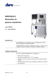
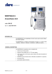
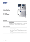
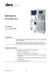
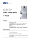
MORPHEUS E
Workstation for gaseous anaesthesia
code: OM9001
rev.: 4 - dd 01/09/2009
DESTINATION OF USE
The MORPHEUS is a workstation for gaseous anaesthesia and it can be
used on adults, children and newborns patients.
The MORPHEUS is suitable for administration of Oxygen - Air -Nitrous
Oxyde - Halothane - Enfluorane - Isoflurane - Sevoflurane - Desflurane Halocarbon 22 mixtures.
GENERAL DESCRIPTION
The unit for anaesthesia MORPHEUS is completed with:
MorpheusE_TFT_te_rev4.doc
-
electronic gas mixing device O2 / N2O / AIR
-
lung ventilator
-
heated closed/open valves group w/2.5 Kg. CO2 absorber
-
double interlock/selectatec support for 2 vaporizers
-
gas supply group
-
breathing monitoring system
1 / 10
GENERALITIES
Structure
Light aluminium alloy, varnished steel and plastic moulds
Wheels
N. 4 - Diameter 100 mm - The two front ones with pedal brakes
Work shelf
Dimensions 37 x 35 - 78 (L x D - H) cm
Shelves
Dimensions 61 x 36 - ( L x D) cm
Max loading capacity 30 Kg
Drawer
No. 2 : inner dimensions 38 x 34 x 14 (L x D x H) cm
Cylinder support
No. 2 vertical cylinder supports, on back side (for cylinders up to 7 lt.
capacity) and round rubber pads.
Vaporizer connection
Double vaporizer connection Selectatec type, with system which avoid the
contemporary opening of the 2 vaporizers.
Auxiliary power supply
outlets
No. 3 outlets SCHUKO 220 Vac (max 10 A)
Work shelf lighting lamp
12Vdc 20Watt
Other
•
Oxygen therapy group
•
Jar group for Venturi tracheal aspiration
Dimensions
73 x 73 x 136 (L x D x H) cm (without monitor)
Weight
100 kg (without accessories)
Environmental
Conditions
Temperature from 10 to 40°C
Relative humidity from 10 to 90% non-condensing
ELECTRONIC GAS MIXING DEVICE
General description
It has the function to regulate the capacity and the concentration of gas
mixture (Air, O2, N2O), showing it on electronic displays, as well as to
deliver it to the anesthetic gas vaporizer.
It allows to select the mixture to be delivered (Air-O2, or N2O-O2) and the
O2 enrichment to the delivered mixture in emergency situations. It includes
a device which guarantees a minimum concentration of 25% oxygen in all
gas erogating conditions (MIX-LIFE device).
Through the three pressure gauges on the front panel it allows the
continuous control of medical gas feeding pressure coming from the gas
pipelines system.
The flowmeter box is electronically controlled and has a traditional type
safety flowmeter indicating the total capacity.
MorpheusE_TFT_te_rev4.doc
2 / 10
Autotest
At the start-up the equipment checks the acoustic indicator and displays
integrity. Moreover eventual gas leakage in the device secondary circuit
are verified, and, in case, the relevant alarm occurs. The test duration is of
approx. 15 seconds and it is not interruptible.
Oxygen rotameter
Scale 0.1 - 15 l/min.
Resolution: 0.1 l/min.
Accuracy: ± 7% of displayed value
Nitrous oxide rotameter
Scale 0.1 - 9 l/min.
Resolution: 0.1 l/min.
Accuracy: ± 7% of displayed value
Air rotameter
Scale 0.1 - 15 l/min.
Resolution: 0.1 l/min.
Accuracy: ± 7% of displayed value
Medical gas supply
OXYGEN
Gas pressure included between 280 kPa and 600 kPa (2,8 – 6 bar).
Max. required flow, 90 l/min.
NITROUS OXYDE
Gas pressure included between 280 kPa and 600 kPa (2,8 – 6 bar).
Max. required flow, 15 l/min.
MEDICAL COMPRESSED AIR
Gas pressure included between 280 kPa and 600 kPa (2,8 – 6 bar).
Max. required flow, 90 l/min
Control gauges
No. 3 on the front panel (O2 - N2O - ARIA ), scale 0 - 10 bar
Power supply
220Vac 50Hz or 110Vac 60Hz
Battery
12Vdc - 1.2Ah Pb battery which guarantees around 1 hour operation
Alarms
•
Oxygen pressure failure or low pressure with consequent block of
nitrous oxide delivery
•
Nitrous oxide pressure failure or low pressure
•
Air pressure failure or low pressure
•
O2 Concentration lower than 20%
•
Power failure
•
Low battery power
•
Gas leakage
MorpheusE_TFT_te_rev4.doc
3 / 10
Safety devices
AGAINST THE ADMINISTRATION OF HYPOXIC MIXTURES
MIX-LIFE: Guarantees a minimum concentration of 25% oxygen on
mixtures that include nitrous oxide (N2O)
IN CASE OF LACK OR LOW OXYGEN PRESSURE
CUT-OFF: Audible alarm with immediate cut-off of nitrous oxide delivery
AGAINST HIGH PRESSURE IN SUPPLY
Safety valve calibrated at 0.8 bar for the protection of the glass rotameters
IN CASE OF LACK OR LOW COMPRESSED AIR PRESSURE
All the devices supplied with compressed air are automatically supplied by
oxygen (except the flowmeter)
AGAINST THE CONTEMPORANEOUS DELIVERY OF AIR AND N20
Selecting valve on the front panel.
Deviator with double
outlet
Device to deviate fresh gas addressing them to the anaesthesia unit valves
group or to a TO and FRO patient circuit for manual ventilation
O2 emergency By-Pass
By push button, on the front panel.
Max. flow 35 l/min.
IN gas socket on gas
supply group
OUT gas socket on gas
supply group
Other
MorpheusE_TFT_te_rev4.doc
•
No. 3 – sockets for distribution system (O2 - N2O - ARIA )
•
No. 2 – sockets for cylinder (O2 - N2O)
•
No. 2 – sockets for O2
•
No. 1 – socket for AIR
•
No. 1 – fresh gas connector for external use for ex. TO and FRO
(selectable by lever on front panel)
•
Socket for recycle of exhaust monitor gas
•
Connection for anesthetic gas scavenging (optional device: 300A or
200P)
4 / 10
BREATHING SYSTEM
General description
Compact system with automatic connections, easy dismountable and
autoclavable
It allows the ventilation in modality: real open circuit, semi-closed
circuit, closed circuit at low flows.
The system also allows the spontaneous and manual ventilation also in
case of machine breakdown or machine off.
The CO2 absorber canister has a rapid connection and this allows its
replacement also during operation.
The recycling system is a selective type, hence the soda lime and fresh
gases consumption is reduced to the minimum.
Reservoir bag orientable support to facilitate the manual ventilation.
The circuit is heated to reduce condensation and heat the fresh gases.
The switching from one modality to another is completely controlled by
ventilator without any user's action on valves group.
All group internal connections are stainless steel made.
The group is completely autoclavable and does not have disposable
parts.
LUNG VENTILATOR
Fixing
On the upper part of the trolley by a quick connection device to the main
structure
Type of Ventilation
IPPV
Control modality
Electronic by microprocessor
The equipment is equipped with an electronic system which, at every
start-up and for a few seconds, verifies all the hardware and software
electronic parts for safety purposes.
O2 cell automatic calibration, leakages test and compliance calculation
are on operator request only.
Dead space compensation Automatic
system
Flow generation
MorpheusE_TFT_te_rev4.doc
Digital System
5 / 10
Gas feeding
Medical Compressed Air or Oxygen with pressure included between
280 kPa and 600 kPa (2,8 – 6 bar)
Ventilation Modes
AUT (IPPV + AST) / PCV / PSV / SPONT - SIMV / APNOEA BACK-UP
/ MANUAL (performed via breathing system or via manual external
system for example, TO and FRO)
Breathing rate
From 5 to 140 bpm
I:E Ratio
1:1 - 1:2 -1:3 - 1:4 - 2:1 - 3:1.
Inspiratory Pause
From 0 to 50% of the inspired time
SIMV Frequency
From 0 to 139
Tidal Volume
From 20 to 1500 ml
Minute Volume
From 1 to 30 liters
PEEP
0-20 cm H2O
Inspiratory Flow
From 0 to 100 lit/min
Built-in with display of O2 concentration
Oxymeter
Min. resolution 1%
Automatic calibration procedure
Bronchomanometer
Electronic with led bar and display from -10 to 80 cmH2O
Trigger (sensibility)
Electronically adjustable in continuous way from -1 to -9 cmH2O under
PEEP level
Safety
Airways pressure electronic and mechanic limit
Self-diagnosis system
User’s Interface
LED Display / Back-enlightened LCD Display / LED bar
Broncomanometer
Other LED indicators / Control keys and knobs
Alarms
LOW/HIGH O2 - HIGH / LOW AIRWAYS PRESSURE - APNOEA POWER SUPPLY - LOW BATTERY - GAS SUPPLY - HIGH/LOW
MINUTE VOLUME - HIGH/LOW TIDAL VOLUME - HIGH/LOW RATE
Flow sensor
By magnetic perturbance, reusable, stérilisable
MorpheusE_TFT_te_rev4.doc
6 / 10
TFT 6,5” colour respiratory monitor
Description
The TFT Monitor can display the respiratory parameters and the curves
and loops clearly, providing immediate information on the patient’s
ventilation.
The user interface and the alarm and patient monitoring functions are
designed to make future equipment updates easier.
The TFT Monitor can be connected to multigas analyzer modules.
Functioning and control
Microprocessor electronic: every time the equipment is switched on, a
check lasting a few seconds is carried out of all the hardware and
software of the system for safety purposes.
Operator interface
Keyboard controls (function selection; ESC; return; alarm silencing) and
Encoder knob
Display area
Parameters measured ; Messages ; Graphs ; Zoom Area ( 2 zone );
Functioning modes
Parameters measured
Pmax, Pmean, Pause, PEEP, Vti, Vte, ExpMV, Rate, FLOWi, FLOWe,
I:E, Tinsp, Tesp, Tpause, Cs, Ri
Messages
Operating mode; Interruptions; Functioning time; Alarm
Graphs available
Ventilation graphs; Loop ; Trend ; Help ; Parameter Zoom page
Zoom Area
2 areas for the selection of the ventilation parameters
Functioning Modes
Zoom Area ( 2 zones ); Alarms setting ( default ); Loop ; Trend ; Help ;
Monitor ; Alarm volume ; Demo display ; Gas type configuration and
selection.
Zoom Area ( 2 zones ) Possibility of selecting and displaying any parameter measured
Alarms Manual or automatic setting of the alarm minimum and maximum limits
Buzzer (volume adjustment) and visual alarm (flashing symbol in the
message area) indication
Alarms: Pmax, Pmean, Ppause, PEEP, VTi, VTe, Expmv, Rate, Cs, Ri.
Ventilation curves Paw ; Flow ; Volume
Loop Volume / Paw ; Volume / Flow
Trend Trend scale and period setting
Trends: Pmax ; Pmean ; Ppause ; PEEP ; VTi ; VTe ; ExpMV ; Rate ;
FLOWi
MorpheusE_TFT_te_rev4.doc
7 / 10
Help Display of the user’s manual ( optional )
Monitor Setting of the following displaying conditions: LCD / Remote 1; LCD /
Remote 0; Zoom parameters page displaying
Zoom Parameter Page Displayed parameters: PEEP ; Flow Insp ; Minute Vol. ; I:E ; Pmax ; Flow
; Exp ; Tidal Volume ; Rate
Displayed curves: Paw ; Flow ; Volume
Gas type configuration •
and selection (optional)
•
Measure gas; Stop gas; Set agent; Set zero; Set O2 %; Set Gas
alarm; Set CO2 unit;
CO2, O2, N2O, AG
Alarm volume
Can be set from 1 to 3
Demo option
Available
Language option
Available
Flow sensor
Automatic setting of OFF-SET and GAIN parameters
Connection
9 poles male connector, RS-232 / Remote monitor
MULTI – GAS ( optional)
Multigas analyzer
modules connection
Available
Description
Ultra small infrared main stream multi-gas probe comprising a multi
channel IR-bench, barometric pressure sensor, power regulator, signal
processor and a RS-232 interface.
Measuring mode
Mainstream
Model
A57.049-301: CO2, O2, N2O, HAL, ENF, ISO, SEV, DES (with Manual
identification of halogenated GAS)
A57.049-601: CO2, N2O, HAL, ENF, ISO, SEV, DES, Agent ID (with
Automatic identification of halogenated GAS)
Dimensions and weight
37 x 27 x 25 mm
< 30 g (cable not included)
General specifications
MorpheusE_TFT_te_rev4.doc
See on relative Multigas Analyzer Modules technical data sheet
8 / 10
POWER SUPPLY
Electric power supply
220 Vac 50-60 Hz (110 Vac optional)
Power
50 W
Internal power supply
12Vdc battery / 3 Ah
Internal battery operation Max. 1,5 hours
Re-charging time
Around 10 hours
CONFORMITY TO NORMS
Class and type according to IEC 601-1
Class 1 Type B
Class according to EEC 93/42 Directive
Class IIB
EN 1281-1, IEC 601-1, IEC 601-1-2, ISO 5369, BS 4272 : Part 3, Dir.va 93/42 EEC, IEC 601-1-4,
UNI EN 740
ACCESSORIES
Supplied accessories
Optional accessories
MorpheusE_TFT_te_rev4.doc
•
User's Manual
•
O2 supply hose
•
N2O supply hose
•
AIR supply hose
•
O2 supply hose for cylinder
•
N2O supply hose for cylinder
•
O2 cell
•
O2 cell cable
•
Supporting arm for patient circuit
•
Jar for Venturi aspirator
•
Yellow Diss connector
•
Silicone patient circuit for adults
•
Mapleson C patient circuit for adults
•
KIT for manual ventilations
•
Scavenging hose
•
Power supply cable
See on Export Price List
9 / 10
SIARE applies the UNI EN ISO 13485:2004 and EEC/93/42 Directive Quality System.
SIARE ENGINEERING INTERNATIONAL GROUP s.r.l.
Via Pastore, 18 40056 Crespellano Bologna – ITALY
Tel : +39 051 969802 - Fax : +39 051 969366
Email : [email protected] - Web : http://www.siare.it
MorpheusE_TFT_te_rev4.doc
10 / 10