1
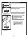
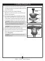
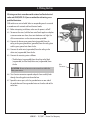
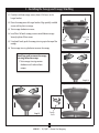
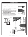
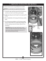
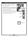
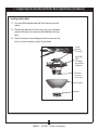
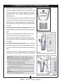
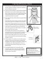
For Your Records and Warranty
Assistance
Model Name: ______________________
Catalog/Model No.: _________________
installation and
operation manual
for Hunter
Ceiling Fans
Serial No.: ________________________
Date Purchased: ____________________
Where Purchased: _ _________________
For reference also attach your receipt or a
copy of your receipt to the manual.
45003-01 • 12/13/07
Welcome
Your new Hunter® ceiling fan is an addition to your home or office that
will provide comfort and performance for many years. This installation
and operation manual gives you complete instructions for installing
and operating your fan.
We are proud of our work. We appreciate the opportunity to supply
you with the best ceiling fan available anywhere in the world.
Before installing your fan, for your records and warranty assistance,
record information from the carton and Hunter nameplate label
(located on the top of the fan motor housing).
Cautions and Warnings
Table of Contents
1 • Getting Ready....................................................4
2 • Installing the Hanger Bracket....................5
3 • Assembling and Hanging the Fan...........6
4 • Wiring the Fan...................................................7
5 • Installing the Canopy and Canopy
Trim Ring...............................................................8
6 • Assembling the Blades..................................9
7 • Completing Your Installation With
a Bowl Light Fixture...................................... 10
8 • Assembling the Remote Control and
Mounting the Cradle................................... 13
9 • Operating and Cleaning Your Ceiling
Fan......................................................................... 15
• READ THIS ENTIRE MANUAL CAREFULLY BEFORE BEGINNING
INSTALLATION. SAVE THESE INSTRUCTIONS.
• Use only Hunter replacement parts.
• To reduce the risk of personal injury, attach the fan directly to the
support structure of the building according to these instructions,
and use only the hardware supplied.
• To avoid possible electrical shock, before installing your fan,
disconnect the power by turning off the circuit breakers to the
outlet box and associated wall switch location. If you cannot lock
the circuit breakers in the off position, securely fasten a prominent
warning device, such as a tag, to the service panel.
• All wiring must be in accordance with national and local electrical
codes and ANSI/NFPA 70. If you are unfamiliar with wiring, use a
qualified electrician.
• To reduce the risk of personal injury, do not bend the blade
attachment system when installing, balancing, or cleaning the fan.
Never insert foreign objects between rotating fan blades.
• To reduce the risk of fire, electrical shock, or motor damage, do not
use a solid-state speed control with this fan. Use only Hunter speed
controls.
10 • Troubleshooting.......................................... 16
© 2007 Hunter Fan Company
2
45003-01 • 12/13/07 • Hunter Fan Company
Installer’s Choice and Optional Accessories
Understanding Mounting and Installer’s Choice®
Support Brace
Standard
Mounting
Style
Ceiling
Outlet Box
Hunter’s patented mounting system provides you maximum
installation flexibility and ease. You can install your Hunter fan in one
of two ways, depending on ceiling height and your preference: Standard
or Angled mounting. The steps in this manual include instructions for
both Installer’s Choice mounting methods.
Considering Optional Accessories
Consider using Hunter’s optional accessories, including a wall-mounted
or remote speed control. To install and use the accessories, follow
the instructions included with each product. For quiet and optimum
performance of your Hunter fan, use only Hunter speed controls.
Standard Mounting hangs from the
ceiling by a downrod (included).
For ceilings higher than 8 feet, you can purchase
Hunter extension downrods. All Hunter fans use
sturdy 3/4” diameter pipe to assure stability and
wobble-free performance.
Support Brace
Ceiling
Outlet Box
8
Angle
Mounting
Style
12
CAUTION: To reduce the risk of personal
injury, attach the fan directly to the support
structure of the building according to these
instructions, and use only the hardware
supplied.
Angled Mounting recommended for a
vaulted or angled ceiling
3
45003-01 • 12/13/07 • Hunter Fan Company
1 • Getting Ready
To install a ceiling fan, be sure you can do the following:
• Locate the ceiling joist or other suitable support in ceiling.
• Drill holes for and install wood screws.
• Identify and connect electrical wires.
• Lift 40 pounds.
If you need help installing the fan, your Hunter fan dealer can direct
you to a licensed installer or electrician.
Gathering the Tools
You will need the following tools for installing the fan:
• Electric drill with 9/64” bit
• Standard screwdriver (magnetic tip recommended)
• Phillips-head screwdriver (magnetic tip recommended)
• Wrench or pliers
• Ladder (height dependent upon installation site)
Checking Your Fan Parts
Carefully unpack your fan to avoid damage to the fan parts. Refer to
the included Parts Guide. Check for any shipping damage to the motor
or fan blades. If any parts are missing or damaged, contact your Hunter
dealer or call Hunter Technical Support Department at 888-830-1326.
Installing Multiple Fans?
If you are installing more than
one fan, keep the fan blades and
blade irons (if applicable) in sets,
as they were shipped.
Preparing the Fan Site
Before you begin installing the fan, follow all the instructions in
the pullout sheet called “Preparing the Fan Site.” Proper ceiling fan
location and attachment to the building structure are essential for
safety, reliable operation, maximum efficiency, and energy savings.
4
45003-01 • 12/13/07 • Hunter Fan Company
2 • Installing the Hanger Bracket
2-1. Drill two pilot holes into the wood support structure through the
outermost holes in the outlet box. The pilot holes should be 9/64”
in diameter.
Isolator
Hanger
Bracket
Note: Your fan comes with four pre-installed neoprene noise
isolators.
2-2. Thread the lead wires from the outlet box down through the hole
in the middle of the hanger bracket.
2-3. Align the slotted holes in the hanger bracket with the pilot holes
you drilled in the wood support structure. For proper alignment
use slotted holes directly across from each other. If you are
installing the fan on an ANGLED ceiling, be sure to orient the
hanger bracket as shown in Illustration 2-3 (left or right view).
Note: The isolators should be flush against the ceiling.
2-4. Place a flat washer on each of the two 3” screws and pass the
screws through the slotted holes in the hanger bracket into the
pilot holes you drilled.
Tighten the screws into the 9/64” pilot holes; do not use lubricants
on the screws. Do not over tighten.
Flat Washer
Steps 2-2 – 2-4
Large
Opening
Ceiling Peak
or
Ceiling Peak
Large
Opening
3” Screw
Left
Step 2-3 (Angled Ceiling Only)
5
45003-01 • 12/13/07 • Hunter Fan Company
RIGHT
3 • Assembling and Hanging the Fan
3-1. To assemble fan to hang down from a flat or angled ceiling, place
the canopy and canopy trim ring around the adapter so that they
rest on the fan assembly.
3-2. Feed the wires from the fan through the downrod.
Note: Make sure all the wires are on the same side of the metal
dowel pin inside the dowrod.
3-3. Loosen the square head set screw on the adapter to install the
pipe and ball assembly. Note: When the pipe and ball assembly
is fully installed, 2-3 threads on the pipe will still be visible; this is
normal. Securely retighten the set screw with a wrench or pliers.
Steps 3-1 – 3-3
Downrod
Canopy
(with Washer)
Adapter
CAUTION: The adapter has a special coating on the threads. Do
not remove this coating; the coating prevents the downrod from
unscrewing. Once assembled, do not remove the downrod.
Canopy
Trim
Ring
Set Screw
WARNING: Do not carry or lift fan by canopy.
3-4. Raise the fan and place the ball into the hanger bracket.
3-5. Align the notch on the ball with the indent in the hanger bracket.
(Rotate the fan until you hear the notch pop into place.)
Go to 4 • Wiring the Fan.
WARNING: Fan may fall if not assembled as directed in these
installation instructions.
Indent
Steps 3-4 – 3-5
6
45003-01 • 12/13/07 • Hunter Fan Company
4 •Wiring the Fan
All wiring must be in accordance with national and local electrical
codes and ANSI/NFPA 70. If you are unfamiliar with wiring, use a
qualified electrician.
Wall switches are not included. Select an acceptable general-use switch
in accordance with national and local electrical codes.
4-1. Before attempting installation, make sure the power is still off.
4-2. To connect the wires, hold the bare metal leads together and place
a wire connector over them, then twist clockwise until tight. For
all these connections use the wire connectors provided.
4-3. Connect the bare or green ground wire (grounded) from the
ceiling to the green ground wire (grounded) from the ceiling plate
and the green ground wire from the fan.
4-4. Connect the white wire (ungrounded) from the ceiling to the
white wire (ungrounded) from the fan.
4-5. Connect the remaining wires as follows:
• The black wire (ungrounded) from the ceiling to the black
(ungrounded) and the black/white wire (ungrounded) from
the fan
CAUTION: Be sure no bare wire or wire strands are visible after
making connections.
Wire
Connector
4-6. Turn the wire connectors upward and push them carefully back
through the ceiling plate into the outlet box.
4-7. Spread the wires apart, with the grounded wires on one side of
the outlet box and the ungrounded wires on the other side of the
outlet box.
7
45003-01 • 12/13/07 • Hunter Fan Company
5 • Installing the Canopy and Canopy Trim Ring
5-1. Partially install two canopy screws (about 2 full turns) in the
hanger bracket.
Steps 5-1 – 5-2
Hanger Bracket
5-2. Raise the canopy over the hanger bracket. Align partially installed
screws with key slots in canopy.
5-3. Twist canopy clockwise to secure.
5-4. Install third & fourth canopy screw in round hole on canopy.
Securely tighten all four screws.
5-5. Using both hands, push the canopy trim ring up to the top of the
canopy.
Canopy
Canopy Trim
Ring
5-6. Twist canopy trim ring clockwise to secure the canopy.
Should you need to remove the canopy
trim ring, follow these steps:
1. Twist canopy trim ring counter
clockwise until it releases from
canopy.
Step 5-3
Step 5-4
Step 5-5
Canopy
Screw
8
45003-01 • 12/13/07 • Hunter Fan Company
6 • Assembling the Blades
Hunter fans use several styles of fan blade irons (brackets that hold the
blade to the fan).
6-1. Your fan may include blade grommets. If your fan has grommets,
insert them by hand into the holes on the blades.
Step 6-1 (Detail)
6-2. Attach each blade to a blade iron using three blade assembly
screws. If you used grommets, the blades may appear slightly loose
after screws are tightened. This is normal.
6-3. Remove the blade mounting screws and rubber shipping bumpers
from the motor. Note: Some blade mounting screws are installed
in the motor to secure shipping blocks.
6-4. For each blade, insert one blade mounting screw through the
blade iron, and attach lightly to the fan. Insert the second blade
mounting screw, then securely tighten both mounting screws.
Use with grommet
Grommet
Steps 6-1 – 6-2
Blade Assembly
Screws
Use without grommet
Blade
Mounting
Screw
Step 6-4
9
45003-01 • 12/13/07 • Hunter Fan Company
7 • Completing Your Installation With a Bowl Light Fixture
Your Hunter fan comes with an integrated light fixture assembly.
WARNING: Use only the light fixture supplied with this fan model.
7-1. To attach the upper switch housing, partially install two housing
assembly screws into the switch housing mounting plate.
7-2. Feed the upper plug connector through the center opening of the
housing.
7-3. Align the keyhole slots in the housing with the housing assembly
screws.
7-4. Turn the housing counterclockwise until the housing assembly
screws are firmly situated in the narrow end of the keyhole slots.
Install the remaining screw into the housing. Tighten all three
screws firmly.
CAUTION: Make sure the upper switch housing is securely
attached to the switch housing mounting plate. Failure to properly
attach and tighten all three assembly screws could result in the
switch housing and/or light fixture falling.
Steps 7-1 – 7-3
Housing
Assembly
Screw
10
45003-01 • 12/13/07 • Hunter Fan Company
Upper
Switch
Housing
7 • Completing Your Installation With a Bowl Light Fixture (Continued)
7-5. To attach the lower switch housing, connect the upper plug
connector from the motor to the lower plug connector in the
lower switch housing assembly.
Note: Both plug connectors are polarized and will only fit together
one way. Make sure the connectors are properly aligned before
connecting them. Incorrect connection could cause improper
operation and damage to the product.
7-6. Place the lower switch housing assembly over the upper switch
housing. Align the side screw holes in the upper and lower switch
housings. Attach the lower switch housing to the upper switch
housing with three housing assembly screws.
Plug
Connector
Steps 7-5 – 7-6
Lower Switch
Housing
Plug
Connector
Detail
Housing
Assembly Screw
11
45003-01 • 12/13/07 • Hunter Fan Company
7 • Completing Your Installation With a Bowl Light Fixture (Continued)
Installing the Glass Bowl
7-7. First install B10 candelabra bulbs (60 Watt Maximum) into the sockets.
7-8. Place the glass bowl over the heater vent, ensuring the threaded
portion of the heater vent comes out of the bottom of the glass
bowl.
7-9. Place the finial over the threaded portion of the heater vent and
twist it as shown to tighten it against the glass bowl.
Switch
Housing
Screws (3)
Light Bulbs
(B10
Candelabra
Base 60 Watt
Maximum)
Threaded
Portion of
Heater Vent
Glass Bowl
Finial
12
45003-01 • 12/13/07 • Hunter Fan Company
8 • Assembling the Remote Control and Mounting the Cradle
8-1. To install the battery, remove the back cover of the remote.
Insert the included 12-volt alkaline battery (Type 23A, MN-21 or
equivalent) inside the remote, matching polarity on the battery
as indicated by the + and - symbols in the battery compartment.
Replace the cover.
If you are using more than one remote controlled fan in the same
area and want to control them separately, you must change the
DIP switch settings in the remote before you install the battery.
For instructions on setting the DIP switches, read the box on the
next page.
8-2. To install the remote cradle on a switch plate, remove the two
screws holding the switch cover plate. Do not remove the cover
plate.
Note: If you are installing the remote cradle on a rocker light
switch, first break off the two tabs by pushing outward.
Orient the control cradle by lining up the two mounting holes
with those on the switch. Insert and tighten the screws (do not
over tighten).
8-3. To install the remote cradle on the wall, locate a 2 x 4 wall stud
in a convenient location. Orient the remote cradle over the 2 x 4
stud. Use 1” wood screws in either the inner or outer mounting
holes.
Wall anchors and 6-32 x 1” screws may be used in situations where
mounting to a stud is not possible. Use the inner mounting holes.
CAUTION: The remote control device complies with part 15 of the
FCC rules. Changes or modifications not expressly approved by Hunter Fan
Company could void your authority to operate this equipment.
Step 8-1
Step 8-2
Removed
Tabs
Operation is subject to the following two conditions:
1. This device may not cause harmful interference.
2. This device must accept any interference received, including interference
that may cause undesired operation.
Note: Use with a fan that incorporates an air gap switch (normal on-off wall
switch).
WARNING: Maximum fan load is 100 Watts; maximum lamp is 300 Watts.
Do not use any speed control with this product.
Step 8-2 (Rocker Light Switch)
13
45003-01 • 12/13/07 • Hunter Fan Company
8 • Assembling the Remote Control and Mounting the Cradle (Continued)
Setting the DIP switches
You will only have to change the DIP switch settings in the remote if you are using more than
one remote controlled fan in the same area and want to control them separately. You may
want to label your remotes to ensure you do not mix them up.
1. At the circuit breaker or fuse box, turn the power off for the fan you want to change. Do
not turn the power off at the circuit breaker for the previously installed fan, as you may
inadvertently change the DIP switch code settings for it as well.
2. Slide the cover off the back of the remote and remove the battery. The battery must be
removed when changing DIP switch settings. Refer to Step 8-1.
3. Change the DIP switch settings, so that they are different from the previously installed
fan.
4. Replace the battery and cover.
5. At the circuit breaker or fuse box, turn the power back on for the fan whose settings you
are changing.
6. Within 20 seconds of restoring power, push the 3 (high), 2 (medium), and 1 (low) buttons
(in that order) on the remote.
Note: The receiver (built into the fan) has a memory function that retains the last DIP
switch code setting. The setting will not change in the event of power failure or if the
power to the fan is inadvertently shut off.
14
45003-01 • 12/13/07 • Hunter Fan Company
9 • Operating and Cleaning Your Ceiling Fan
9-1. To start the fan, press the speed button on the remote at the level
you desire: 3 for high, 2 for medium, 1 for low. To turn off the fan,
press the off button on the remote.
9-2. Ceiling fans work best by blowing air downward (counterclockwise
blade rotation) in warm weather to cool the room with a direct
breeze. In winter, having the fan draw air upward (clockwise blade
rotation) will distribute the warmer air trapped at the ceiling
around the room without causing a draft. 9-3. You can control the light and heater blower using separate buttons
on the remote.
Normal Operation: For normal ceiling fan operation (low, medium,
high and reverse speeds), the heater blower must be turned off.
Heater Function: For operation of the heater only, make sure the
ceiling fan is turned OFF, and then push the heater button on the
remote control. For operation of the heater and the ceiling fan
at the same time, you must turn ON the ceiling fan in any speed,
before turning ON the heater function.
Note: Regardless of the speed setting, when the ceiling fan is
operating while the heater function is turned ON, the ceiling fan
automatically switches to low-speed updraft only and will not
operate at high or medium speeds or reverse. (This assures you will
get the maximum benefit of the heater function when the ceiling
fan blades are rotating).
9-4. For cleaning finishes, use a soft brush or lint-free cloth to prevent
scratching. A vacuum cleaner brush nozzle can remove heavier
dust. Remove surface smudges or accumulated dirt and dust using
a mild detergent and a slightly dampened cloth. You may use
an artistic agent, but never abrasive cleaning agents, as they will
damage the finish.
9-5. Clean wood finish blades with a furniture polishing cloth.
Occasionally, apply a light coat of furniture polish for added
protection and beauty. Clean painted and high-gloss blades in
the same manner as the fan finish.
Light
Heater
Fan
Medium
Fan Low
Fan Off
Steps 9-1 – 9-2
Fan High
Reversing
Switch
Warm Weather =
Downward Airflow
Cold Weather =
Upward Airflow
To Change Airflow Direction
Turn the fan off and let it come to a
complete stop. Press the reversing switch
on the remote. Restart fan.
15
45003-01 • 12/13/07 • Hunter Fan Company
10 • Troubleshooting
Problem: Nothing happens; fan does not move.
1.Turn power on, replace fuse, or reset breaker.
2.Loosen canopy, check all connections according to the wiring the
fan section.
3.Check the plug connection in the switch housing.
4.Push motor reversing switch firmly left or right to ensure that the
switch is engaged.
5.Pull the pull chain to ensure it is on.
6.Remove the shipping bumpers.
Problem: Noisy operation.
1.Tighten the blade bracket screws until snug.
2.Check to see if the blade is cracked. If so, replace all the blades.
Problem: Excessive wobbling.
1.If your fan wobbles when operating, use the enclosed balancing kit
and instructions to balance the fan.
2.Tighten all blade iron screws.
3.Turn power off, support fan very carefully, and check that the
hanger ball is properly seated.
If you need parts or service assistance, please call
888‑830‑1326 or visit us at our Web site at
http://www.hunterfan.com.
Hunter Fan Company
2500 Frisco Avenue
Memphis, Tennessee 38114
16
45003-01 • 12/13/07 • Hunter Fan Company