1
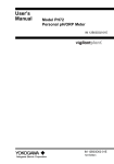
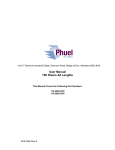
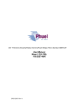
Unit 17 Denmore Industrial Estate, Denmore Road, Bridge of Don, Aberdeen AB23 8JW
User Manual
Grayloc Riser
This Manual Covers the Following Part Numbers:
115-3068-HV0
OPS-3068 Rev C
User Manual
Grayloc Riser
Table of Contents
Revision History ........................................................................................... ii
Safety.............................................................................................................. iii
1 Introduction ............................................................................................... 1
1.1
General .............................................................................................. 1
1.2
Product Identification ......................................................................... 1
2 Technical Specification ............................................................................. 2
3 Technical Description ............................................................................... 3
3.1
Metal Seal Ring ................................................................................. 3
3.2
Two Hubs .......................................................................................... 3
3.3
Clamp Assembly ................................................................................ 3
4 Operation .................................................................................................. 4
4.1
Lifting ................................................................................................. 4
4.2
Before Assembly ............................................................................... 4
4.3
Assembly ........................................................................................... 5
4.4
Disassembly ...................................................................................... 6
4.5
Pre Job .............................................................................................. 6
4.6
During Job ......................................................................................... 6
4.7
Post Job............................................................................................. 6
5 Maintenance ............................................................................................. 7
5.1
Introduction ........................................................................................ 7
5.2
Schedule............................................................................................ 7
5.3
Safety ................................................................................................ 8
5.4
Maintenance Record Sheet ............................................................... 9
6 Testing .................................................................................................... 10
7 Parts List and Drawings .......................................................................... 11
Table 1 : Technical Data .................................................................................. 2
Table 2: Maintenance Record .......................................................................... 9
Table 3: Parts List 115-3068 .......................................................................... 11
Figure 1 : Riser Safety .................................................................................... iii
Figure 2 : Riser ................................................................................................ 2
Figure 5: Grayloc Riser .................................................................................. 12
OPS-3068 Rev C
i
User Manual
Grayloc Riser
Revision History
Issue, Release Date
Rev A, 29 Oct 10
Rev B, 10 Jan 11
Rev C, 11 Jan 11
OPS-3068 Rev C
Description
Initial Issue
Seal Ring was BX 156 (Sect 7)
Supporting Equipt Update
ii
User Manual
Grayloc Riser
Safety
WARNING: Trapped air requires considerable time to compress and
when it is compressed is highly dangerous. It has enough stored
energy to separate parts with considerable force.
Seals in high-pressure vessels are also susceptible to explosive
decompression; the O-rings or rubber gaskets used to seal pressurised
pipelines tend to become saturated with high-pressure gases. If the
pressure inside the vessel is suddenly released, then the gases within
the rubber gasket may expand violently, causing blistering or explosion
of the material.
All pressure equipment has a particular pressure rating and care must be
taken to ensure that no item is used in a situation that may cause its working
pressure to be exceeded.
All personnel involved in pressure testing must be formally trained, competent
and utilising the appropriate PPE.
Safe Lok devices, where used, should be checked for positional security to
avoid unnecessary movement of the collar
Ensure the identification band/plate is fitted and is displaying the correct
information as per the Tag Sheet/Index
This equipment and the equipment it is attached to is heavy never position
yourself below a suspended load
Care to be taken to
avoid trapping fingers,
gloves and loose
clothing during stabbing
procedure
OPS-3068 Rev C
Figure 1 : Riser Safety
iii
User Manual
Grayloc Riser
1 Introduction
1.1 General
The Phuel Grayloc Riser (or Lubricator) is a pressure containing cylinder used
when performing wireline operations. Its purpose is to allow the wireline tool
string to be raised above the wellhead valve allowing entry and exit from the
well bore.
The Riser body is constructed in one piece with a metal-to-metal Grayloc
sealing end connections.
This user manual serves as an introduction to the equipment and contains the
relevant specifications, operation, planning and maintenance instructions,
parts list and drawings.
1.2 Product Identification
Phuel products are identified by a unique serial number that facilitates full
product traceability. Each product is supplied with a documentation pack that
contains product certification and material/inspection reports. The serial
number is always etched on the surface of the product but can sometimes be
difficult to find or read after painting.
A stainless steel band secures the nameplate tag that is stamped with the
information shown. This tag should be located in the first instance to ensure
that this manual refers to the correct equipment. A customer identification
number is also included to allow the customer to track the asset in their
system
PHUEL OIL TOOLS LTD
DESCRIPTION & SIZE
CUSTOMER ID No
PHUEL ID No 06-XXX-XX
MWP & SERVICE
TEST DATE
OPS-3068 Rev C
1
User Manual
Grayloc Riser
2 Technical Specification
Part Number
114-3064
I/D
6.375’’
Length (A)
147.21’’ / 3.74 m
Weight
3912 lbs / 1774 kg
Maximum Working Pressure
15,000 Psi
Maximum Test Presure
22,500 Psi
End Connection
Grayloc M12/72
Side Conmnection
3.06 BX Side Outlet
Table 1 : Technical Data
Figure 2 : Riser
OPS-3068 Rev C
2
User Manual
Grayloc Riser
3 Technical Description
3.1 Metal Seal Ring
The seal ring resembles a "T" cross section. The leg of the "T" forms a rib that
is held by the hub faces as the connection is made-up. The two arms form lip
seals that create an area of sealing surface with the inner surface of the hub.
Internal pressure works to reinforce this seal.
3.2 Two Hubs
The clamp fits over the two hubs and forces them against the seal ring rib. As
the hubs are drawn together by the clamp assembly, the seal ring lips deflect
against the inner sealing surfaces of the hubs. This deflection elastically loads
the lips of the seal ring against the inner sealing surface of the hub, forming a
self-energized seal.
3.3 Clamp Assembly
Designed to provide nearly 360° clamping contact with the hubs. A relief notch
in the centre of the clamp segments allow even distribution of makeup forces.
No specific orientation is required when installed.
The rib of the seal ring is clamped between hub faces. The lips of The seal
ring engage the inner hub surface with an interference fit which deflects the
lips to achieve a seal.
OPS-3068 Rev C
3
User Manual
Grayloc Riser
4 Operation
All operations to be carried out by suitably qualified and competent
personnel
4.1 Lifting
End protectors should always be fitted when lifting or moving the riser.
4.1.1 Vertical
The Riser should be lifted with a suitable lifting clamp or cap that is rated for
the total lifting load, following the instructions for the clamp or cap being used.
If practical leave the thread protectors fitted until ready to make up the
connections.
4.1.2 Horizontal
Suitable slings can be wrapped around either end of the riser to allow
horizontal lifting for means of transportation or fitting. Always pay attention to
the centre of gravity and do not continue to lift if the lubricator is not sitting
horizontal as it might slip through the slings.
4.2 Before Assembly
The Grayloc seal ring does not seat until the connection is fully
tightened; therefore, a small clearance, or standoff, between the ring rib
and hub face should be observed when the ring is placed into a mating
hub. If no standoff is present, use a new seal ring.
Clean all lubricants and foreign matter from the hub seating surfaces
before installation. Use a non-abrasive material to clean the seal rings
of all foreign matter. Normally, all seal rings have a coating or plating
(cadmium, PTFE, MoS2) which acts as a lubricant during make-up. In
some applications where uncoated/ unplated seal rings are used, a
light film of clean lubricant is recommended.
When applying lubricant, take special care to ensure that no solid or
foreign particles are present in the lubricant. Also, take care to prevent
mechanical damage to the seal ring and the hub sealing surfaces.
Before assembly, the hubs must be aligned to allow engagement of the
seal ring lips to the hub sealing surfaces. This will ensure proper
engagement of the hub and clamp segments.
OPS-3068 Rev C
4
User Manual
Grayloc Riser
4.3 Assembly
Align the hubs so that the seal ring can be installed between the hubs.
Install the seal ring in the sealing surface of the hubs. The seal ring
should rock slightly; i.e., the seal ring rib should not be able to firmly
contact the hub face. If it does not rock, use a new seal ring.
Install the clamps around the hubs. Apply lubrication to the hub-clamp
contact area to reduce friction; this will aid assembly.
Insert the stud bolts into the bolt holes of the clamp ears. Install the
nuts, ensuring that the spherical surfaces of the nuts and the clamp are
in proper position for mating.
Lubrication of the bolting and the spherical faces of the nuts and the
clamp is recommended.
Tighten the bolting in a criss-cross pattern (i.e., bolt #1, #3, #2, #4) to
keep the spacing between the clamp halves approximately equal.
To properly preload the Grayloc connector against gasket loads, fluid
pressure loading, thermal shock loading, and normal pipe reaction
loads, the torque values of 870 lbft (1180 Nm) is recommended. Note
that torque wrenches are not required, but are recommended to ensure
that the minimum preload values are met.
Assembly should include jarring the clamps during the bolting
procedures, i.e., a sound blow to the back of the clamp with a soft
hammer (torque, jar, torque, jar, etc.) until bolt torque does not change
after jarring.
At full make-up, the hub faces will shoulder flush against the seal ring
rib. The seal ring rib will prevent over torquing from causing seal
damage, but to prevent permanent damage from distortion of the other
components of the connection, the maximum torque applied to the
connection should not be more than twice the values shown in the
table. For extreme misalignment and/or extreme piping loads, torque
values 1'h to 2 times the table values are recommended. Lubricated
bolting should be used to assemble the Grayloc connector..
OPS-3068 Rev C
5
User Manual
Grayloc Riser
4.4 Disassembly
Before disassembling the Grayloc connector, bleed all pressure from the line.
When removing the clamp, first loosen the bolting and the clamp set from the
hubs to allow the safe release of any trapped pressure. Then, remove the
bolting completely.
4.5 Pre Job
Ensure end protectors are fitted
Check maintenance record sheet and ensure the equipment has been
maintained by competent personnel
Check all certification is in date
Confirm information band is fitted and correct
Ensure equipment is suitable for the maximum working pressures and
services involved
Inspect for signs of damage
Pressure test to at least 1.2x the maximum well pressure
Ensure all connections are tight
4.6 During Job
Avoid excessive movement
4.7 Post Job
Inspect for signs of damage
Ensure protectors are fitted
OPS-3068 Rev C
6
User Manual
Grayloc Riser
5 Maintenance
All maintenance to be carried out by suitably qualified and competent
personnel
5.1 Introduction
Regular maintenance of the equipment using Phuel redress kits or Phuel
approved parts is essential to its continued safe operation. Ensure that the pre
and post job operating procedures are followed and that maintenance records
are kept.
Special maintenance is not required for a Grayloc connector that has been
properly assembled. However, when disassembling a connector, check the
seal ring for standoff prior to reassembly and visually inspect the hub seats for
uniformity and freedom from burrs and deep scratches. These irregularities on
ring seal surfaces could cause leakage.
Remove scale, rust, burrs, or deep scratches from a ring seat by lightly
polishing with a fine steel wool or crocus cloth around the seat circumference
to ensure uniform blending-in of the reworked area. Never lap the hub seat
with the seal ring; this practice will damage both the ring and the seat and
prevent an effective seal.
The connector should not be tightened while under pressure loading or severe
mechanical loads. Do not weld on Grayloc clamps, bolting or seal rings
without consulting Grayloc Products.
All components of the Grayloc assembly should be obtained only from
Grayloc Products or one of its authorized licensees. Do not substitute nonGrayloc brand parts in Grayloc connectors.
5.2 Schedule
The maintenance schedule may be governed by international or company
standards and the following is considered to be the minimum requirements.
5.2.1 Pre & Post Job
Refer to Section 4.5 and Section 4.7 for details
5.2.2 Yearly
Disassemble riser clean and degrease all components
Inspect the condition of all sealing surfaces and surface coatings
OPS-3068 Rev C
7
User Manual
Grayloc Riser
Re-coat sealing surfaces if necessary. If in doubt contact Phuel Oil
Tools Ltd
Regrease components
Re-assemble – torque side outlet bolts to 706Nm (523 ft-lb)
Pressure test to maximum working pressure in accordance to testing
procedure (see 6)
Inspect paint work and repair as necessary
5.2.3 Five Yearly
Yearly Maintenance (plus the following)
Carry out surface NDE on all component threads and damaged
surfaces
Pressure test to test pressure (witnessed by certifying authority where
applicable)
Repaint
5.3 Safety
Many of the components are heavy and should not be lifted without
lifting aids.
Ensure all pressure testing is carried out in the appropriate testing area
by suitably qualified personnel.
Wear appropriate personal protective equipment.
Do not over exert yourself while using torque wrenches. Use
appropriate mechanical advantages when available.
Ensure that all tools and equipment are in good condition and are
suitable for the intended use.
Clear up any fluid spills immediately to avoid slips.
OPS-3068 Rev C
8
User Manual
Grayloc Riser
5.4 Maintenance Record Sheet
Date
Type of
Performed
Performed Maintenance
By
Verified
By
Comments
Table 2: Maintenance Record
OPS-3068 Rev C
9
User Manual
Grayloc Riser
6 Testing
All testing is to be carried out in the designated test area and by suitably
qualified and competent personnel.
WARNING: Trapped air requires considerable time to compress and
when it is compressed is highly dangerous. It has enough stored
energy to separate parts with considerable force
On completion of reassembly fit the appropriate test caps to either end
of the riser
Fill with test fluid and bleed off any air in the system
Apply a pressure of 500 psi and ensure pressure holds for a minimum
of 10 minutes
Increase pressure to Maximum Working Pressure, allow to stabilise
and maintain this pressure for a minimum of 15 Minutes ensuring there
are no apparent leaks. .
Bleed off pressure, drain test fluid and dry
Remove test caps and plug
Apply coating of de-watering solution to protect the bore
Fit protectors
On completion of all maintenance ensure the maintenance record sheet (Para
5.4) is completed
OPS-3068 Rev C
10
User Manual
Grayloc Riser
7 Parts List and Drawings
Item Number
Part Number
1
115-3120-480
2
3
4
5
128-2216-A2H
900-3253-STL
125-3357-AB7
950-3366-475
Quantity
Description
1
15K RISER 3.74M
(GRAYLOC M12/72 W/ 3.06 BX)
8
HEAVY DUTY NUT 1.125-8 UN
1
SEAL RING BX 154 (Soft Iron)
8
STUDS - 1.125-8 UN X 6 LONG
1
3-1/16in BLANK FLANGE (15K)
Table 3: Parts List 115-3068
Note: The nuts (2) are to be torqued to 523 ft-lbs (706 Nm)
8 Spares
Use only spares supplied or approved by Phuel Oil Tools Ltd.
It is recommended that sufficient quantities of the following spares be
maintained to ensure that the equipment is always available when required.
8.1.1 Individual Items
Individual items may be ordered as required using the part number specified
8.1.2 Supporting Equipment
The following are available for order directly from Phuel Oil Tools Ltd or can
be procured directly from your local Grayloc distributer if marked thus *.
Part No.
Item Description Comments
*A90501-9
*H90136-17
Grayloc Clamp 12M
Studs & Nuts for
Clamp 12M
AISI 4140 NACE (ASTM A 193 B7M)
ASTM A193 B7/A194 Gr2H, Zinc Plated
*66814
*A91072-4
950-3825-STL
Seal Ring Size 72
Blind Test Hub
Lubricator Lift Clamp
AISI 4140 NACE PTFE Coated
Size 12M 72 with 9/16 Autoclave
25 Ton SWL with 2m of chains
Table 4 : Supporting Equipment
OPS-3068 Rev C
11
User Manual
15K Risers All Lengths
Figure 3: Grayloc Riser
OPS-3064 Rev C
12