1
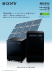
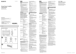
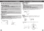
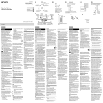
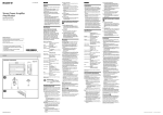
4-410-047-11(1) Energy Storage Module / Controller User’s Manual IJ1001M IJ1001C/IJ1002C/IJ4001C © 2011 Sony Corporation Introduction Thank you for choosing Sony’s energy storage module/controller. The energy storage module comprises of lithium ion rechargeable batteries with 1.2 kWh capacity, and the controller enables a central of multiple modules. This manual provides information regarding safety precautions to prevent possible accidents and how to use the product. Please read this manual carefully before use for safety and keep this manual handy for reference. Main Features Long life span The battery can be expected to remain serviceable for more than 10 years, provided it is charged and discharged once in a day at room temperature (23 deg. C). Higher Safety Olivine-type lithium iron phosphate batteries with excellent thermal stability and storage characteristics are used in this product. The module also incorporates a self-monitoring function, for detection of any abnormalities in energy storage. The monitored status can be communicated to an external controller to safely control the usage state of the battery. Quick Charge More than 90% of the capacity can be charged in one hour. High Scalability Multiple energy storage modules can be connected to the controller, and voltage and capacity can be customized according to the intended use. 2 Table of Contents Introduction . . . . . . . . . . . . . . . . . . . . . . . . . . . . . . . . . . . . . . . . 2 Main Features . . . . . . . . . . . . . . . . . . . . . . . . . . . . . . . . . . . . . . . 2 Accessories (included/sold separately) . . . . . . . . . . . . . . . 4 Accessories for controller . . . . . . . . . . . . . . . . . . . . . . . . . . . . 4 Accessories for storage module . . . . . . . . . . . . . . . . . . . . . . 4 Other accessories sold separately . . . . . . . . . . . . . . . . . . . . 4 Safety Precautions . . . . . . . . . . . . . . . . . . . . . . . . . . . . . . . . . . 5 Precautions for use . . . . . . . . . . . . . . . . . . . . . . . . . . . . . . . . . . 8 Function Overview . . . . . . . . . . . . . . . . . . . . . . . . . . . . . . . . . . 9 Controller . . . . . . . . . . . . . . . . . . . . . . . . . . . . . . . . . . . . . . . . . . . . 9 Energy Storage Module . . . . . . . . . . . . . . . . . . . . . . . . . . . . . . 9 Part Names and Functions . . . . . . . . . . . . . . . . . . . . . . . . . . 10 Controller . . . . . . . . . . . . . . . . . . . . . . . . . . . . . . . . . . . . . . . . . . . 10 Energy Storage Module . . . . . . . . . . . . . . . . . . . . . . . . . . . . . 14 Installation . . . . . . . . . . . . . . . . . . . . . . . . . . . . . . . . . . . . . . . . 15 Installation Procedure . . . . . . . . . . . . . . . . . . . . . . . . . . . . . . . 15 Connection Method . . . . . . . . . . . . . . . . . . . . . . . . . . . . . . . . 16 Connection Procedure . . . . . . . . . . . . . . . . . . . . . . . . . . . . . . 18 Charging . . . . . . . . . . . . . . . . . . . . . . . . . . . . . . . . . . . . . . . . . . 20 Charging voltage and current . . . . . . . . . . . . . . . . . . . . . . . 20 Replacing Energy Storage Modules . . . . . . . . . . . . . . . . . 21 Error Messages . . . . . . . . . . . . . . . . . . . . . . . . . . . . . . . . . . . . . 22 Main Specifications . . . . . . . . . . . . . . . . . . . . . . . . . . . . . . . . 23 Other . . . . . . . . . . . . . . . . . . . . . . . . . . . . . . . . . . . . . . . . . . . . . . 24 Accessories (included/sold separately) Accessories for controller ˎˎScrew (M4×8) (for attaching bracket) (2) ˎˎBracket (2) ˎˎScrew (M4×8) (for fixing brackets) (4) Other accessories sold separately It is recommended to use only Sony products with the following model numbers. ˎˎCommunication cable 0.3 m (IJT-003) 1.0 m (IJT-010) Accessories for storage module ˎˎTermination connector IJS-001 ˎˎPower connector (1) ˎˎPower cable ˎˎScrew (M3×6) (for securing power connector) (2) ˎˎBracket (2) For IJ1001C/IJ4001C 0.3 m (IJD-003: Red, Black) 1.0 m (IJD-010: Red, Black) For IJ1002C 0.3 m (IJD-103: Red, Black) 1.0 m (IJD-110: Red, Black) Note ˎˎIf you use a power cable other than the one shown above, be sure to select a cable with suitable current rating. Please contact Sony sales representative in case of damage or missing accessories, or when purchasing other accessories sold separately. 4 Safety Precautions Sony products are designed with full consideration on safety. However, all electrical appliances can be dangerous if used inappropriately; it can cause a fire or electric shock that leads to serious injury or death. For your protection, please read these safety precautions completely. Definition of Symbols Below are symbols used in this manual and the unit. Please read through the following definitions before reading the manual. Warning If you ignore these instructions, it can lead to a fire or electric shock causing serious injury or death. Warning If you do not follow the instructions below, it can lead to a fire or electric shock causing serious injury or death. Instruction A non-designated cable use can cause electric shock. Be sure to use the cable designated in this manual. Caution If you ignore these instructions, it can lead to electric shock or other accidents causing injury or harm to nearby products. Use designated cable Prohibited Do not damage cables If you damage a cable, it can cause a fire or electric shock. ˎˎDo not work over or damage a cable. ˎˎDo not place heavy objects on a cable or pull the cable. ˎˎDo not place a heater near the cable, which may result in the cable overheating. ˎˎDo not tuck down a cable when installing in a rack. ˎˎWhen you unplug a communication cable, be sure to hold the plug and pull it. Instruction Connect a power cable and communication cable properly If you connect a power cable improperly, contact resistance will increase and it may damage the parts or cause a fire. Insert the connector of the communication cable all the way in. If it is connected improperly, the system may be deactivated. 5 Safety Precautions Prohibited Do not install in a closed area If the module/controller is installed in a closed area with no air-conditioning, heat may build up inside the set and cause a fire. Prohibited Do not place the set in direct sunlight or near a heater Caution If you ignore any of the following instructions, it can cause injury or damage to nearby products. Prohibited If the vent is covered, heat may build up inside the set and cause a fire. ˎˎDo not put the set in a poorly ventilated and narrow space. ˎˎRemove any dust buildup in the vent. ˎˎDo not place the set upside down or sideways. ˎˎDo not place on a shag carpet or bed. ˎˎDo not cover the vent with a cloth, etc. Doing so can cause deformation, a breakdown, or a fire. Pay extra attention when you place the set near windows. Prohibited Do not install the set where excessive oil smoke, steam, moisture or dust is contained in the air If the set is installed in such a place, it may cause a fire or electric shock. Instruction No wet Do not open the set unnecessarily Opening and modifying the set can cause a fire or electric shock. Install in a stable place If you install the set in an unstable place, such as an unstable rack, it may fall and cause injury. Do not install upside down or sideways. The set may drop and cause injury. Instruction Use the designated packaging materials for transportation If you do not use the designated packaging materials, the packaging material may be damaged by vibration during transportation and it may cause injury. Do not allow water and/or foreign objects inside the module Water or foreign objects inside the module can cause a fire or electric shock. Should this occur, however, turn off the “POWER ON/OFF” switch on the controller to shut down, and remove the power connector from the POWER CONNECTOR terminal of the module. Do not disassemble Instruction Wear insulating gloves and protection glasses during installation and connection Wear insulating gloves and protection glasses during installation and connection of the set to prevent electric shock or other injuries. Do not cover the vent Instruction Install based on the designated way of installation If you do not follow the designated way of installation, the set may drop due to the strength poverty and can cause injury. Instruction Fix a rack to the floor If a rack falls by the weight of the set, it may cause serious injury or death. 6 Safety Precautions No wet Do not touch with wet hands If you touch the set with wet hands, it may cause electric shock. Instruction Install other equipment or accessories properly If you inadequately install other equipment or accessories sold separately they may fall and cause injury. When you install any of the following accessories, install it properly based on this manual. ˎˎBracket ˎˎPower connector Instruction Danger If liquid is leaking from the module, observe the following measures. ˎˎDo not allow the liquid to come in contact with skin or clothing. ˎˎIf the liquid comes in contact with skin or clothing, wash thoroughly with plenty of water. ˎˎIf the liquid gets into the eyes or mouth, flush immediately with clean water, and immediately seek medical treatment. ˎˎContact customer service. Set up cables properly If your foot is caught by a cable, the set may fall and cause injury. Connect and install cables carefully. Instruction Power off at a malfunction In case any malfunction happens, please turn off the POWER ON/OFF switch in order to shut down, and remove the power connector from the POWER CONNECTOR terminal of the module. Prohibited Do not put anything, stand or sit on the set If you put anything on the set, it may fall and cause injury. Also, if it is used as a stool, for example, it may topple and cause injury. Instruction Follow related laws or ordinances for disposal When you dispose of this product, do not dispose as general or household waste. Instruction Disposal with specified method Contact technical vendor when you discard. Do not disassemble, destroy, or disposal in the fire. 7 Safety Precautions Precautions for use Description of the controller Controller and Module ˎˎDo not disassemble ˎˎDo not modify the product (Modification may destroy the protection function inside, or cause abnormal charge/ discharge, heat generation, gas eruption, or fire.) ˎˎRefer to “Connection Method” on Page 16 and follow the procedure when you connect a cable to the product. ˎˎIn the case of a failure, or any of the abnormalities shown below, turn off the set and contact Sony customer services. sound, smell or smoke ˋAbnormal ˋ or particles inside the product ˋWater ˋ ˋThe ˋ product is dropped or the cabinet is damaged ˎˎDo not touch the rear output terminal except for installation. ˎˎDo not throw the product into fire or heat, or otherwise expose the set to heat or naked flame. ˎˎDo not submerge the product in liquid, or allow it to become wet. ˎˎDo not apply strong shock, crush, or drop. ˎˎDo not use for medical purposes. ˎˎDo not place any foreign objects inside. ˎˎDo not connect any devices that exceed the operating voltage and current range. Module description Energy Storage Module ˎˎCharge and discharge the product according to the control signals of the controller. ˎˎDo not hammer a nail or punch a hole in the product. ˎˎDo not unplug the power connector from the POWER CONNECTOR terminal while power is turned on. ˎˎReplace the module with a new one if discharge time at room temperature is noticeably short, even from fully charged. 8 Function Overview Controller Connect multiple modules to the controller and control charge/discharge current. Controlling charge/discharge current Control charge/discharge by communicating with a module. Charge will stop when the charge signal output from a module becomes low. Charge will stop when “Over Voltage” signal output from a module becomes low. Discharge will stop when the discharge signal output from a module becomes low. LCD Display Panel Information from a module (charge/discharge status, voltage/current, capacity, temperature, etc.) is communicated to the controller, and appears on the display panel on the front of the controller. Communication with Host Information on a module and the controller can be communicated to a host via the RS232C or CAN communication terminal. Protection against overcurrent Provides fuse protection against overcurrent. An output control switch is also included. Energy Storage Module Charge and discharge control Charge/discharge are controlled by 3 signal lines, charge, discharge, and overvoltage. In the following cases, the charge signal becomes low ˎˎMaximum cell voltage exceeds specified voltage range ˎˎTemperature exceeds specified range while charging ˎˎOvercurrent flows while charging ˎˎCharging completes In the following cases, the discharge signal becomes low ˎˎOverdischarge ˎˎTemperature exceeds specified range while discharging ˎˎOvercurrent flows while discharging In the following cases, the over voltage signal becomes low ˎˎOvervoltage ˎˎTemperature exceeds specified range while charging ˎˎOvercurrent flows while charging Auto-power on and auto-shut down circuit Shuts down the system automatically after a module is completely discharged. When an external charging voltage is applied, the system will be powered on automatically. 9 Part Names and Functions Controller Front LCD Display Panel Displays information on the status of a module (charge/ discharge, total voltage, total current, total remaining capacity, number of connected modules, remaining capacity of each module, cell block voltage/temperature etc.). For further details, please refer to “Display Panel” on page 12. Indicator LED Normal status: Green Error status: Red (flashing) POWER ON/OFF switch Power on (operating) / off (interrupt current) the controller and modules. DISP button Switches the displayed information on the display panel 10 Part Names and Functions Rear CHG lamp/DIS lamp CHG lamp: lights green when ready to be charged DIS lamp: lights green when ready to be discharged CAN communication terminal Communicate with the host using CAN protocol. RS232C communication terminal Communicate with the host using RS232C protocol. EB+ terminal Connect to the + terminal of external devices. B+ terminal Connect to the B+ terminal of a module. CHG lamp/DIS lamp CHG lamp: lights green when ready to be charged DIS lamp: lights green on when ready to be discharged CAN communication terminal Communicate with the host using CAN protocol. RS232C communication terminal Communicate with the host using RS232C protocol. EB+ terminal Connect to the + terminal of external devices. B+ terminal Connect to the B+ terminal of a module. HEATER- terminal When using the optional heater, connect its – terminal to HEATER– (white), and its + terminal to EB+. EB− terminal Connect to the − terminal of external devices. B− terminal Connect to the B− terminal of a module. GND terminal, SW ON terminal, terminal Interrupts charge/discharge current from a module when a resistor (100Ω) is connected between the GND terminal and SW ON terminal. The terminal is connected to earth. I/F(U) terminal / I/F(l) terminal The I/F(U) terminal is connected to the I/F(L) terminal of a module. The I/F(l) terminal is not used. EB− terminal Connect to the − terminal of external devices. B− terminal Connect to the B− terminal of a module. terminal, 12V terminal, GND terminal, SW ON terminal, TH terminal The terminal is connected to earth. 12V terminal connects to the 12V terminal of a thermostat. Charge/discharge current from a module can be blocked by connecting a resistor (100Ω) between the GND terminal and SW ON terminal. The TH terminal connects to the TH terminal of a heater unit. I/F(U) terminal / I/F(l) terminal The I/F(U) terminal is connected to the I/F(L) terminal of a module. The I/F(l) terminal is not used. 11 Part Names and Functions Display Panel Press the DISP button to display information on a panel. Display switching-over flow Turn on Display system’s overall status Overall Display status of each module Connection Module #00 Module #N Status Status Mode Mode Cell Temp Cell Temp Alarm bits Alarm bits Heatsink Setting for “Comm Off Mode” #N means top-level module : Press and hold DISP switch : Press DISP switch Tips ˎˎHold the DISP button more than 3 seconds. ˎˎIf you press and hold the DISP button during “Connection” Display, the display panel goes back to “Overall”. ˎˎ“Comm Off Mode” is used for maintenance. Display images “Overall” Display MODE=DIS RSOC= 30% Item MODE RSOC I V “Connection” Display I=- 10.0A V= 300.0V Details Display Charge/discharge DIS: discharge and stop status CHG: charge OFF: stop (Available only when a resistor (100Ω) is connected between the GND and SW ON terminals.) Remaining 0% - 100% System Capacity Total system -999.9A - +999.9A current Total system 0.0V - 999.9V voltage UNIT=6 VER=1000 CON=----------oooooo Item UNIT VER CON Details Number of connected module Version Connected module status Display 1 - 16 XXXX Sample above indicates 6 modules (#00 - #05) are connected. 12 Part Names and Functions “Status” Display “Cell Temp., Cycle Count” Display M_NO=01 STAT=32[Normal Chg ] Item M_NO STAT Details Display Number of 00 – 15 displayed module Status of module YX (Y: Current status, X: Previous status) 0X 1X [Pre Charge]: Pre Charge 2X [Initial]: Initial 3X [Normal Chg]: Normal Charge 4X [Terminate]: Charge Terminate 5X [Normal Dis]: Normal Discharge 6X [Over Volt]: Over Voltage 7X [Over Dis]: Over Discharge 8X 9X [Over Temp C]: Over Temp Charge AX [Over Curr C]: Over Current Charge BX [Over Temp D]: Over Temp Discharge CX [Over Curr D]: Over Current Discharge DX [Unbalance]: Cell Unbalance EX [Chg Suspend]: Charge Suspend FX “Mode, Current, SOC, Voltage” Display M_NO=01 RSOC= 30% Item M_NO RSOC I V Details Number of displayed module Remaining module capacity Module current Module voltage I=+ 10.0A V= 51.2V Display 00 – 15 0% - 100% M_NO=01 CYCL=0001 Item M_NO CYCL T Details Number of displayed module Cycle count Average temperature of all cells T=+ 23.0C Display 00 – 15 0000 – 9999 -99.9C - +99.9C “Alarm bits” Display M_NO=01 ALRM=0000[ Item M_NO ALRM ] Details Display Number of 00 – 15 displayed module Status of module 8000 [Over Volt]: Over Voltage 4000 [Terminate]: Charge Terminate 2000 [Under Vol]: Under Voltage 1000 [Over Curr]: Over Current 0800 [Over Temp]: Over Temp 0400 [0 ]: 0200 [Resister]: Alarm Resister 0100 [Unbalance]: Cell Unbalance Display when multiple alarms are detected Example: If both “Over Current” and “Over Temp” are detected, the following message is displayed. A higher bit level takes precedence for messages in parentheses. “ALRM=1800 [Over Curr]” “Heatsink Temp” Display -999.9A - +999.9A 0.0V – 999.9V HEATSINK_TMP=+ 23C Item Details HEATSINK_TMP Temperature of heatsink Display -40C - +119C 13 Part Names and Functions Energy Storage Module Front Indicator LED Normal Status: Green Error Status: Red (flashing) Rear I/F(U) terminal/ I/F(L) terminal Connect to the controller, or other modules. B+ terminal Connect to the controller, or other modules. POWER lamp/ ALARM lamp POWER lamp: Green ALARM lamp: Red (flashing) B− terminal Connect to the controller, or other modules. POWER CONNECTOR terminal Insert the provided power connector. Never insert the power connector until installation and connection of the set has been completed. Please refer to “Connection Method” (page 16) for details. Rotary Switch Set the address (0 to 9, A to F) of a module (page 18). 14 Installation Installation Procedure Follow the procedure below to properly install. Note ˎˎBefore installing a module, make sure the power connector on the rear is unplugged, and the controller’s POWER ON/OFF switch is set to OFF. 1 Align the convex parts of the bracket () with the concave parts of the module () and attach the bracket with screws (M4×8/tightening torque:1N•m) 2 Place the controller/module in the rack. 3 Attach the controller/module to the rack with the (bracket) screws. Screws used for attaching to a rack are not included in the set. Please use screws attached with a rack. Notes ˎˎEIA standard 19-inch rack is recommended. ˎˎAlways use a rack with support plate when you install on a rack. Use one plate per product. 15 Installation 1 Connect the B− terminal of an upper module to the B− terminal of a lower module. 2 Connect the B+ terminal of an upper module to the B+ terminal of a lower module. 3 Connect the B− terminal of the bottom module (#00) to the B− terminal of the controller. ˎˎMake sure the power connector on the rear of the module is unplugged, and the controller’s POWER ON/OFF switch is set to OFF. 4 Connect the B+ terminal of the bottom module (#15) to the B+ terminal of the controller. IJ1001C/IJ1002C Parallel connection (up to 16) The required storage capacity can be achieved without changing voltage. 5 Connect the EB+ and EB− terminals of the controller to the + and − terminals of external devices (charger, inverter etc.). IJ4001C Series connection (up to 7) Storage capacity increases and necessary voltage can be achieved by adjusting the number of series-connected units. Series and parallel connection (up to 7 series, 2 parallel) Take advantages of both series and parallel connections. ˎˎBefore connecting the set, all the modules’ RSOC and V (voltage) settings should all be set to within 3% and 0.5 V (respectively) of each other. Connection Method Depending on the controller type, the connection method will vary. For details on the connection of communication cables, refer to page 18. Note Note Parallel Connection (IJ1001C/ IJ1002C) e.g. 16 parallel connection to host to external devices controller module#15 (top level) module#05 module#04 module#03 module#02 module#01 module#00 (bottom level) 16 Installation Serial Connection (IJ4001C only) e.g. 7 series connection to host Series and Parallel Connection (IJ4001C only) e.g. 7 series and 2 parallel connection to external devices to host to external devices controller controller module#06 (top level) module#13 (top level) module#05 module#12 module#04 module#03 module#05 module#02 module#04 module#01 module#03 module#00 (bottom level) module#02 1 Connect the B− terminal of an upper module to the B+ terminal of a lower module. module#01 2 Connect the B+ terminal of the bottom module (#00) to the B+ terminal of the controller. module#00 (bottom level) 3 Connect the B+ terminal of the top level module (#06) to the B+ terminal of the controller. 4 Connect the EB+ and EB− terminals of the controller to the + and − terminals of external devices (charger, inverter etc.) Note ˎˎBefore connecting the set, all the modules’ RSOC and V (voltage) settings should all be set to within 3% and 0.5 V (respectively) of each other. 1 Make a parallel connection with 2 modules as one pair (Connect B−, B+ terminals of a pair) 2 Connect the B− terminal of the lower module of a pair to the B+ of the upper module of the lower pair. 3 Connect the B− terminal of the bottom module (#00) to the B− terminal of the controller. 4 Connect the B+ terminal of the top module (#13) to the B+ terminal of the controller. 5 Connect the EB+ and EB− terminals of the controller to the + and − terminals of external devices (charger, inverter etc.) Note ˎˎBefore connecting the set, all the modules’ RSOC and V (voltage) settings should all be set to within 3% and 0.5 V (respectively) of each other. 17 Installation Connection Procedure Please follow the procedure below to connect the set properly. 3 Connect a termination connector to the I/F(U) terminal of the top module. 4 Set an address for each module (0-9, A-F) by the rotary switch on each module. Rotate the (recessed) arrow in the center of the rotary switch with a precision flathead screwdriver to set an address (indicated by the arrow). Notes ˎˎMake sure the power connector on the rear of the module is unplugged, and controller’s POWER ON/OFF switch is set to OFF. ˎˎDepending on the controller types, the connection method will vary. For further details, refer to page 16. ˎˎWear insulating gloves and protection glasses to prevent electric shock and injury. 45 23 6 789 Connect the power cable Connect a power cable to the EB+, EB−, B+, and B− terminal of the controller, and the B+ and B− terminals of a module, and the + and − terminals of external devices. Remove a terminal cover and a screw and attach a power cable with a screw (tightening torque: 2.5N•m). Then, replace the cover. CD AB E F01 1 Arrow Note ˎˎAlways set the bottom module to “0” and use then series numbers for the other modules. The top-level module needs to be the maximum number. 5 Confirm all connections. Check all connections for any mistakes. 6 Insert a power connector in the rear of all modules and secure with a screw (M3×8/tightening torque: 0.6N•m). Both heads of the connector must be inserted all the way in. 7 Turn on the POWER ON/OFF switch of the controller. The controller and all modules are powered on. Cover Turn a flat side to a device. 2 Connect the communication cable. Connect the I/F(U) terminal of the controller to the I/F(L) terminal of the bottom module. Connect the I/F(U) terminal of a lower module to the I/F(L) terminal of the upper module. Connect the 8-pin end of the communication cable to the I/F(U) terminal, and connect the 12-pin side of the communication cable to the I/F (L) terminal. Hook Hook Turn a hook left. Notes ˎˎInsert the hook firmly until it clicks. ˎˎThe I/F(L) terminal of the controller is not used. 18 Installation Connect to a Host You can confirm the information on the controller and modules by connecting to the CAN communication and RS232C communication terminal of the controller. Connect to Earth Connect the terminal on the controller to earth. Confirm the Status of the Controller and Modules You can confirm the status of charge/discharge, remaining capacity, current/voltage value, etc., on the display panel of the controller. Press the DISP button (3 seconds) to switch display information. For further details, refer to “Display Panel” in “Part Names and Functions” on page 12. Turn off Turn off the POWER ON/OFF switch of the controller. The controller and all modules are turned off. 19 Charging Charging voltage and current Conduct charging by constant current and constant voltage within the specified rating of the module. charging voltage constant voltage (CV) 57.6 V CC/CV charging performance curve 0 constant current (CC) 24 A charging current Notes ˎˎCharge the module by setting a charging voltage of 57.6 ±0.8V and a charging current of lower than 24 A with constant current and constant voltage. (Note that the maximum current is limited by the maximum current of the controller.) ˎˎDischarge a module at lower than 50A. (Note that the maximum current is limited by the maximum current of the controller.) ˎˎThe controller stops discharging when it reaches the minimum voltage. ˎˎCharging current may be shut down by the controller when charging is almost finished. 20 Replacing Energy Storage Modules Please read ”Installation Procedure” on page 15 and “”Connection Method” page 16 before you replace modules, and be sure to confirm the power connector on the rear side of the module is unplugged, and the controller’s POWER ON/ OFF switch is OFF. Note ˎˎBefore connecting the set, all the modules’ RSOC and V (voltage) settings should all be set to within 3% and 0.5 V (respectively) of each other. 21 Error Messages When an error message is displayed on the controller, confirm the followings to handle the set properly. If a message does not disappear after following the below measures, please contact Sony customer services. Item NO MODULE Other message Item COMM OFF MODE Details For maintenance only Details No module connection Display Connect modules. If the left message appears when modules are connected, confirm that they are properly connected OV ERROR Over voltage error Please discharge DISCHARGE ERROR Over discharge error Please charge COMM ERROR Communication error Confirm the connection of with connected CON= -------------------ooox modules. Example on communication the left indicates the cables case when 1 module (#00) has a communication error, 3 modules (#01, #02, #03) are connected, and the other addresses have no connection. 22 Main Specifications Controller (IJ1001C/IJ1002C/IJ4001C) Energy Storage Module Operating Voltage Range 30 V to 60 V (IJ1001C/IJ1002C) 60 V to 420 V (IJ4001C) Operating Current Range 0 A to 50 A (IJ1001C/IJ4001C) 0 A to 100 A (IJ1002C) Storage Temperature -40 ºC to 65 ºC Operating Temperature -20 ºC to 60 ºC Relative Humidity Less than 95% (non condensation) Connection Parallel connection (upto 16 series) (IJ1001C/IJ1002C) / Series connection (upto 7 series), Series and parallel connection (up to 7 series, 2 parallel) (IJ4001C) Weight Approx. 7 kg (IJ1001C) / Approx. 8 kg (IJ1002C/IJ4001C) Dimensions Approx. 432 mm x 80 mm x 421 mm (width x height x depth) Nominal Capacity 1.2 kWh, 24 Ah (32.0 V Cut Off ) Rating Capacity 1.1 kWh, 22 Ah Nominal Voltage 51.2 V Max Output Power2.5 kW Max Discharge Current 50 A Charging Voltage 57.6 V ±0.8 V Max Charging Current 24 A Charging Time Approx. 2.5 h Storage Temperature -40 ºC to 65 ºC Operating Temperature Charge 0 ºC to 45 ºC Discharge -20 ºC to 60 ºC (Discharge Current ≤ 24A) -20 ºC to 40 ºC (24 A < Discharge Current ≤ 50 A) Relative Humidity Less than 95% (non condensation) Weight Approx. 17 kg Dimensions Approx. 432 mm x 80 mm x 421 mm (width x height x depth) 23 Other Recycling of Lithium Ion Battery Inquiries and Services Battery manufacturer are obligated to collect and recycle lithium ion batteries, as used in these energy storage modules, based on the law, “Act on the Promotion of Effective Utilization of Resources” (enforced from April 2001), issued in Japan. When disposing of the set, please recycle and observe local regulations to protect the environment. ˎˎIn case of product failure (hardware) during appropriate use during the warranty period, please contact Sony customer services. We will repair free of charge. ˎˎThe following cases are exempt from warranty cover: Please contact Sony sales representative for details on recycling batteries. (1) Requesting repair after warranty period for failure occurring within warranty period. (2) Failure/Damage due to misuse (includes when proper handling based on the Users’ Manual, Caution Label on product, etc., is neglected). (3) Failure caused by other devices or damage by inappropriate repair or modification. (4) Failure/Damage caused by relocation, transportation, dropping, etc., after purchase. (5) Failure/Damage from fire, earthquake, wind, flood, thunder, or other natural disaster, public hazard, salt damage, abnormal voltage, etc. ˎˎPlease contact Sony sales representative for inquires and warranty on the product 24