1
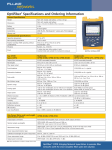
FIBER QUICKMAP ™ Multimode Troubleshooter Users Manual January 2011, Rev. 2 7/13 ©2011-2013 Fluke Corporation All product names are trademarks of their respective companies. LIMITED WARRANTY AND LIMITATION OF LIABILITY Fluke Networks mainframe products will be free from defects in material and workmanship for one year from the date of purchase. Parts, accessories, product repairs and services are warranted for 90 days, unless otherwise stated. Ni-Cad, Ni-MH and Li-Ion batteries, cables or other peripherals are all considered parts or accessories. This warranty does not cover damage from accident, neglect, misuse, alteration, contamination, or abnormal conditions of operation or handling. Resellers are not authorized to extend any other warranty on Fluke Networks’ behalf. To obtain service during the warranty period, contact your nearest Fluke Networks authorized service center to obtain return authorization information, then send your defective product to that Service Center with a description of the problem. THIS WARRANTY IS YOUR ONLY REMEDY. NO OTHER WARRANTIES, SUCH AS FITNESS FOR A PARTICULAR PURPOSE, ARE EXPRESSED OR IMPLIED. FLUKE NETWORKS IS NOT LIABLE FOR ANY SPECIAL, INDIRECT, INCIDENTAL OR CONSEQUENTIAL DAMAGES OR LOSSES, ARISING FROM ANY CAUSE OR THEORY. Since some states or countries do not allow the exclusion or limitation of an implied warranty or of incidental or consequential damages, this limitation of liability may not apply to you. 4/04 Fluke Networks PO Box 777 Everett, WA 98206-0777 USA Contents Introduction .................................................................................... 1 Registering Your Product .............................................................. 1 The Fluke Networks Knowledge Base......................................... 1 Safety Information ......................................................................... 2 Battery Installation and Life.......................................................... 4 Physical Features............................................................................. 4 Settings ............................................................................................ 8 The Connector Adapter................................................................. 9 How to Clean Connectors and Adapters..................................... 9 How to Clean the Connector on the Troubleshooter .......... 9 How to Clean Bulkhead Connectors ...................................... 10 How to Clean Connector Ends................................................. 11 About Launch and Receive Fibers ................................................ 11 How to Use the Troubleshooter................................................... 12 Measurement Results..................................................................... 14 Maintenance ................................................................................... 18 Contacting Fluke Networks........................................................... 19 Options and Accessories ................................................................ 20 Specifications................................................................................... 21 i FIBER QUICKMAP Users Manual ii Introduction The FIBER QUICKMAP™ Multimode Troubleshooter does these tests to help you find incidents on multimode fiber optic cables: • Maps the connections in multimode fiber plants by showing the number of incidents on the fiber and the distance to each incident. • Measures the length of multimode fiber optic cables • Measures the distance to reflective and loss incidents • Measures the reflectance of connectors Registering Your Product When you register your product with Fluke Networks you get access to valuable information on updates, troubleshooting procedures, and other support services. To register online, go to www.flukenetworks.com/registration. Or, send the registration card that came with this product to Fluke Networks. The Fluke Networks Knowledge Base The Fluke Networks Knowledge Base gives answers to typical questions about Fluke Networks products and includes information on technology and procedures for network and cable tests. To see the Knowledge Base, go to www.flukenetworks.com, then click SUPPORT > Knowledge Base. 1 FIBER QUICKMAP Users Manual Safety Information Warning or Caution: Risk of damage to or destruction of equipment or software. See explanations in the manual. Warning: Risk of electrical shock. Warning: Class 1 laser. Risk of damage to your eyes caused by hazardous radiation. Do not put products that contain circuit boards into waste containers. Refer to local regulations for disposal procedures. Warning: Class 1 Laser To prevent possible damage to your eyes caused by hazardous radiation: • Do not look directly into optical connectors. Some optical equipment emits invisible radiation that can cause permanent damage to your eyes. • Do not turn on the troubleshooter unless a fiber is attached to the port. • Do not use a magnifying device to look at the optical outputs without the correct filter. • Use of controls, adjustments, or procedures that are not in this manual can cause exposure to hazardous radiation. 2 Safety Information Caution To prevent damage to fiber connectors, to prevent data loss, and to make sure that your test results are as accurate as possible: • Do not connect APC connectors to the troubleshooter. An APC connector will cause damage to the fiber endface in the connector on the troubleshooter. • Use only test cords that comply with GR-326-CORE specifications and have UPC connectors. Other test cords can cause unreliable measurements. • Use the correct procedures to clean all fiber connectors before each test. If you do not do this or if you use incorrect procedures, you can get unreliable test results and can cause permanent damage to the connectors. • Put protective caps on all connectors when you do not use them. • If you use the LC adapter: When your work with the LC adapter is completed, replace it with the SC adapter and put the protective cap on the SC adapter. • Do not connect the troubleshooter to a network that is on. If you do, the troubleshooter can cause problems in the network. • If ACTIVE LINE blinks, immediately disconnect the troubleshooter from the fiber. Optical power levels more than +7 dBm can cause damage to the detector in the troubleshooter. • The troubleshooter senses optical signals only at 850 nm. If there might be signals at other wavelengths on a fiber, use a different instrument to make sure that the fiber is not active before you connect the troubleshooter to the fiber. 3 FIBER QUICKMAP Users Manual Battery Installation and Life AA IEC LR6 NEDA 15A Note: Fluke Networks recommends alkaline batteries. fjy03.eps Figure 1. How to Install the Batteries The troubleshooter can do approximately 1500 tests before you must replace the batteries. Physical Features See Figure 2. Output port with SC adapter and UPC endface Starts a test On/off key Navigation keys Press to see the setup menu, to select an item, and to save a setting LCD display 4 Physical Features gbw04.eps Figure 2. Physical Features 5 FIBER QUICKMAP Users Manual L K J I F H G gbw01.eps Figure 3. Display Features When the low battery symbol shows, replace the batteries soon. See page 4. When you press , the troubleshooter looks for an 850 nm optical signal on the fiber. If there is an 850 nm signal stronger than -15 dBm on the fiber, ACTIVE LINE blinks and the troubleshooter will not do a test. Caution If ACTIVE LINE blinks, immediately disconnect the troubleshooter from the fiber. Optical power levels more than +7 dBm can cause damage to the detector in the troubleshooter. 6 Physical Features The troubleshooter senses optical signals only at 850 nm. If there might be signals at other wavelengths on a fiber, use a different instrument to make sure that the fiber is not active before you connect the troubleshooter to the fiber. The digits show the fiber length in feet or meters. Shows when you look at the setting for the backlight timer. The setting is in seconds. Shows when you look at the setting for the reflection limit. The setting is in decibels. R: Shows the reflectance of an incident on the fiber. The measurement is in decibels. MORE : Shows when the troubleshooter finds more than one incident. Press to see the reflectance of the incidents. The numbers show the number of the incident and the total number of incidents. ERROR: Shows an error number for error conditions. TESTING: Shows as the troubleshooter does a test. BREAK OR END: Shows when the troubleshooter shows the distance to a break or the end of the fiber. : Shows when the length is more than the range of the troubleshooter. See page 17. Settings for the troubleshooter. LOSS LIMIT and REFLECTION LIMIT blink after a test if a measurement exceeded the limit you select. 7 FIBER QUICKMAP Users Manual Settings To change the settings on the troubleshooter: 1 Press . 2 To select a setting to change, press , then press . 3 Use to change the setting. 4 Press or to save the setting. BACKLIGHT The display backlight turns off if you do not press a key for the period of time shown. You can set the time to 15 to 60 seconds in increments of 5 seconds. I.O.R. (index of refraction) The index of refraction is the ratio of the speed of light in a vacuum to the speed of light in a fiber. The troubleshooter uses the index of refraction to calculate length. If you increase n, the calculated length decreases. The default is 1.496. This value is satisfactory for most fibers. ft/m Select feet or meters as the unit for length measurements. LOSS LIMIT Sets the minimum value of power loss for incidents that the troubleshooter shows an incident. You can select a value from 0.50 dB (lower loss) to 6.10 dB (higher loss) in 0.2 dB increments. The default is 0.70 dB. Note When you change the loss limit, the troubleshooter also applies the new limit to the results shown from a previous test. 8 The Connector Adapter REFLECTION LIMIT Sets the minimum size of a reflection that the troubleshooter shows as an incident or the end of the fiber. You can select a value from -20 dB (larger reflection) to -45 dB (smaller reflection) in 5 dB increments. The default is -35 dB. The Connector Adapter The troubleshooter has an SC connector adapter that you can remove to clean the fiber endface in the port (Figure 4). How to Clean Connectors and Adapters Always clean and do an inspection on fiber connectors before you make connections. Use fiber optic solvent and optical-grade wipers or swabs to clean connectors. You can purchase these supplies from Fluke Networks. How to Clean the Connector on the Troubleshooter 1 Turn off the troubleshooter. 2 Remove the connector adapter to get access to the ferrule (see Figure 4). 3 Touch the tip of an optical-grade solvent pen or swab soaked in solvent to a dry, optical-grade wiper. 4 Touch a new, dry swab to the solvent on the wiper. 5 Twist the swab around against the fiber endface 3 to 5 times, then twist a dry swab around against the fiber endface 3 to 5 times. 9 FIBER QUICKMAP Users Manual Remove Unlock Ferrule and fiber endface Lock fjy02.eps Figure 4. How to Remove and Install the Connector Adapter How to Clean Bulkhead Connectors (sources and patch panels) 1 Do steps 3 and 4 from the previous section to put solvent on a swab. 2 Push the swab into the connector, twist it around 3 to 5 times against the endface, then discard the swab. 3 Twist a dry swab around in the connector 3 to 5 times. 4 Before you make a connection, use a fiber microscope (for example, the Fluke Networks FIBERINSPECTOR™ Video Microscope) to do an inspection on the connector. 10 About Launch and Receive Fibers How to Clean Connector Ends 1 Touch the tip of an optical-grade solvent pen or swab soaked in solvent to a dry, optical-grade wiper. 2 Rub the connector endface across the solvent on the wiper, then rub it two times across the dry area of the wiper. Note A different procedure is necessary to clean some connector styles (for example, VF-45). Always put protective caps on connectors you do not use. At intervals, clean the caps with a swab or wipers and fiber optic solvent. About Launch and Receive Fibers Launch and receive fibers give the troubleshooter a better view of the first and last connectors in the link. If you do not use a launch fiber, the troubleshooter cannot detect the loss of the first connector in the link. If you do not use a receive fiber, the troubleshooter cannot detect the loss of the last connector in the link. Also, the reflectance measurement for the first and last connectors will be inaccurate. Fluke Networks recommends that you use launch and receive fibers. The fibers must have a minimum length of 30 m (98 ft). When you use launch and receive fibers, be sure to subtract their lengths from the length measurement to get the actual length of the fiber you are testing. 11 FIBER QUICKMAP Users Manual How to Use the Troubleshooter Note Always use test cords that comply with GR-326-CORE specifications and have UPC connectors. Other cords can cause unreliable measurements. 1 Clean all fiber connectors. 2 Connect the fiber to the troubleshooter, as shown in Figure 5. Note Use launch and receive fibers if you connect to spooled fiber that is terminated with connectors. 3 Turn on the troubleshooter, then press . Note After you turn on the troubleshooter, it shows for a short time to show that it operates correctly. Caution If ACTIVE LINE blinks, immediately disconnect the troubleshooter from the fiber. Optical power levels more than +7 dBm can cause damage to the detector in the troubleshooter. 12 How to Use the Troubleshooter Installed fiber Launch fiber Patch panel Patch panel Receive fiber Note: Always use test cords that comply with GR-326-CORE specifications and have UPC connectors. Unterminated spool of fiber Mechanical splice gbw05.eps Figure 5. How to Make Connections 13 FIBER QUICKMAP Users Manual Measurement Results The troubleshooter measures the reflectance of incidents on the fiber and the distance to the incidents. A reflective incident will most frequently be the end of the fiber, a break in the fiber, or a connector. The troubleshooter shows the distance to loss incidents that are higher than the limit you selected. A loss incident can be a connector, a bad splice, a crack, or a sharp bend in the fiber. After a test, the troubleshooter shows the distance to the end of the fiber or to a break. If there is a break in the fiber, the troubleshooter does not show incidents after the break. If the troubleshooter shows MORE , it found one or more reflective or loss incidents before the end of the fiber or the break. Press to see the distance to the other incidents. See Figures 6 and 7. Note Be sure to subtract the lengths of the launch and receive fibers from the results. If the reflectance or loss of a connection is higher than the limit: • A connector endface is dirty or damaged. • A connector is loose. • The cable is damaged within about 3 m of the connector. • The connection is between fibers of different types. • The fiber has a bad splice or a sharp bend. 14 Measurement Results Blinking The length of the receive fiber is 105 m. Typically, the reflectance of the end of a fiber is higher than the limit. Blinking The end of the link. The loss of this connection is higher than the limit. The length of the link (without the launch fiber) is 360.8 m. Blinking A bad splice on the fiber at 92.7 m caused a loss incident that is higher than the limit. The reflectance of the first connection is -48 dB. The length of the launch fiber is 105 m. gbw02.eps Figure 6. Examples of Results 15 FIBER QUICKMAP Users Manual Blinking The end of the receive fiber. The end of the link. The length (without the launch fiber) is 868.6 m. 503.6 m 500.8 m The troubleshooter can possibly show short patch cords as one incident. This occurs because the reflection from the second connection is hidden in the reflection from the first connection. gbw03.eps Figure 7. Results from a Link with a Short Patch Cord 16 Measurement Results The troubleshooter can show these results in the given situations: The troubleshooter shows m, ft, or a very short length. • The connection to the troubleshooter is bad. • The connector on the troubleshooter or the fiber is dirty. See page 10 for instructions on how to clean the connectors. • A break, bad connection, or the end of the fiber is less than approximately 1 m from the troubleshooter. • The troubleshooter is connected to a PC connector. PC connectors cause large reflections that the troubleshooter shows as the end of the fiber. The troubleshooter shows m or ft. The fiber is longer than the troubleshooter can measure. The troubleshooter shows <-55 dB for a reflectance measurement. The troubleshooter does not show an exact measurement for very small reflective incidents less than -55 dB. The length measurement is incorrect. • The I.O.R. (index of refraction) is incorrect. See page 8. • The fiber is very short (approximately 1 m or less). The condition of the connectors on the meter and the fiber can affect length measurements on short fibers. The total number of incidents shows , and the is blinking. • There are more than 9 incidents on the fiber. To see the incidents, do a test from the other end of the fiber. 17 FIBER QUICKMAP Users Manual Maintenance To clean the display, use lens cleaner and a soft, lint-free cloth. To clean the case, use a soft cloth that is moist with water or water and a weak soap. Caution To prevent damage to the display or the case, do not use solvents or abrasive materials. To clean the optical connector, use the procedure given on page 10. Warning To prevent possible fire, electrical shock, personal injury, or damage to the troubleshooter: • Do not open the case. You cannot repair or replace parts in the case. • Use only replacement parts that are approved by Fluke Networks. • If you replace parts that are not specified as replacement parts, the warranty will not apply to the product and you can make the product dangerous to use. • Use only service centers that are approved by Fluke Networks. Note If the troubleshooter shows ERROR , servicing is necessary. Speak to a Fluke Networks representative. See page 19. 18 Contacting Fluke Networks Contacting Fluke Networks www.flukenetworks.com [email protected] +1-425-446-4519 • Australia: 61 (2) 8850-3333 or 61 (3) 9329 0244 • Beijing: 86 (10) 6512-3435 • Brazil: 11 3759 7600 • Canada: 1-800-363-5853 • Europe: +31-(0) 40 2675 600 • Hong Kong: 852 2721-3228 • Japan: 03-6714-3117 • Korea: 82 2 539-6311 • Singapore: +65-6799-5566 • Taiwan: (886) 2-227-83199 • USA: 1-800-283-5853 For more phone numbers, go to our website. 19 FIBER QUICKMAP Users Manual Options and Accessories For a complete list of options and accessories go to the Fluke Networks website at www.flukenetworks.com. Option or Accessory Fluke Networks Model Number SIMPLIFIBER PRO Multimode Fiber Verification Kit FTK1000 VISIFAULT™ Visual Fault Locator VisiFault FT500 FIBERINSPECTOR™ Mini Video Microscope FT500 FT500 FIBERINSPECTOR™ Mini Video Microscope and Fiber Optic Cleaning Kit FT525 FT120 FIBERVIEWER™ Microscope, 200X FT120 FT140 FIBERVIEWER Microscope, 400X FT140 Fiber Optic Cleaning Kit with carrying case NFC-Kit-Case Fiber Optic Cleaning Kit NFC-Kit-Box Test reference cord, 62.5/125 µm, SC/SC, 1 m NFK1-1SMPLX-SC Test reference cord, 62.5/125 µm, SC/LC, 1 m NFK1-1SMPLX-LC Test reference cord, 62.5/125 µm, SC/ST, 1 m NFK1-1SMPLX-ST Test reference cord, 50/125 µm, SC/SC, 1 m NFK2-1SMPLX-SC Test reference cord, 50/125 µm, SC/LC, 1 m NFK2-1SMPLX-LC Test reference cord, 50/125 µm, SC/ST 1 m NFK2-1SMPLX-ST ™ Launch/receive fiber, 62.5/125 µm, SC/SC, 105 m NFK1-LAUNCH Launch/receive fiber, 62.5/125 µm, SC/LC, 105 m NFK1-LAUNCH-LC Launch/receive fiber, 62.5/125 µm, SC/FC, 105 m NFK1-LAUNCH-FC Launch/receive fiber, 62.5/125 µm, SC/ST, 105 m NFK1-LAUNCH-ST Launch/receive fiber, 50/125 µm, SC/SC, 105 m NFK2-LAUNCH 20 Specifications Option or Accessory Fluke Networks Model Number Launch/receive fiber, 50/125 µm, SC/LC, 105 m NFK2-LAUNCH-LC Launch/receive fiber, 50/125 µm, SC/FC, 105 m NFK2-LAUNCH-FC Launch/receive fiber, 50/125 µm, SC/ST, 105 m NFK2-LAUNCH-ST Launch/receive fiber, 50/125 µm, SC/E2K, 105 m NFK2-LAUNCH-E2K Interchangeable LC adapter LC-ADAPTER ST/ST fiber optic adapter NF300SM SC/SC fiber optic adapter NF310SM Soft carrying case and holster FIBR-AC-CH Specifications Specifications are typical. Operating temperature with the battery 0ºC to 50ºC Non-operating temperature -20ºC to 60ºC Operating relative humidity (without condensation) 95% (10ºC to 35ºC) 75% (35ºC to 40ºC) uncontrolled < 10ºC Vibration Random, 5 Hz to 500 Hz, MIL-PRF-28800F CLASS 2 Shock 1 meter drop test Safety CSA C22.2 No. 61010.1:04 EN 61010-1 2nd Edition 2001 EN60825-1,2:2006 Altitude 3000 m 21 FIBER QUICKMAP Users Manual EMC EN 61326-1: 2004 Battery type 2 AA alkaline batteries (no battery charger) Battery life 1500 tests (typical) Laser safety Class 1 CDRH Complies to EN 60825-2 LCD type Backlit black and white (segments) Index of refraction range 1.45 to 1.5 (factory default is 1.496) Auto turn off Automatically turns off after 5 minutes if no keys are pressed. Backlight turns off first. Factory calibration interval None Output wavelengths 850 nm ± 10 nm Laser classification Class 1 CDRH Complies to EN 60825-2 Dynamic range >11 dB Maximum distance 1500 meters or 4921 feet Maximum number of incidents shown 9 Distance accuracy (0 m to 1500 m or 0 ft to 4921 ft) ± (1 m + 0.1 % x length) for reflective incidents1 ± (3 m + 0.1 % x length) for non-reflective incidents2 Testing speed < 6 seconds typical Connector Removable/cleanable SC adapter, UPC polish Fiber types tested 50/125 µm or 62.5/125 µm multimode 1. ± user-configurable Index of Refraction (IOR) error ± the incident location error. Incident location error for reflective incidents: ±1 m from 1 m to 1.5 km. 2. ± user-configurable Index of Refraction (IOR) error ± the incident location error. Incident location error for non-reflective incidents: ±2 m for lengths ≤15 m, otherwise ±1 m. 22 Specifications Detection of reflective incidents3 -35 dB default threshold (User selectable: -20 dB to -45 dB in 5 dB increments) Reflectance accuracy4 ± 4 dB Maximum reflectance measurement -20 dB Detection of loss incidents5 0.70 dB default threshold (userconfigurable from 0.5 dB to 6.1 dB in 0.2 dB increments) Bulkhead quality If no fiber is attached or if the connector is dirty, the troubleshooter displays 0 m or 0 ft. Live fiber detection Detects optical signals from 600 nm to 1050 nm and shows ACTIVE LINE if a signal is there. Looks for a signal every 3 seconds after the first detection. +7 dBm maximum input power. Conforms to relevant European Union directives Conforms to relevant Australian standards Listed by the Canadian Standards Association CSA C22.2 No. 61010.1.04 Conforms to FCC Rules, Part A, Class A 3. Finds and gives the location of an incident that has a reflectance larger than -55 dB. Detects incidents >1 m after the bulkhead connector when the bulkhead reflectance is <-35 dB. Detects incidents >6 m (typical) after an incident when the incident reflectance is <-35 dB. 4. With a backscatter coefficient of -63 dB at 850 nm using a calibrated -14 dB reference. 5. Detects incidents >20 m (typical) after the bulkhead connector or any prior incident when the bulkhead reflectance is <-35 dB and the reflectance of any prior incident is <-35 dB. The maximum link loss prior to the incident is <7 dB. 23 FIBER QUICKMAP Users Manual 24