1
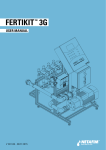
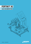
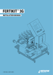
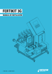
FERTIKIT 3G
™
SALES DOCUMENTATION
V 001.08 - MAY 2015
Use of symbols
The symbols used in this manual refer to the following:
WARNING
The following text contains instructions aimed at preventing bodily injury or direct damage to
the crops, the product and/or the infrastructure.
CAUTION
The following text contains instructions aimed at preventing unwanted system operation,
installation or conditions that, if not followed, might void the warranty.
ATTENTION
The following text contains instructions aimed at enhancing the efficiency of usage of the
instructions in the manual.
NOTE
The following text contains instructions aimed at emphasizing certain aspect of the operation of
the system or installation.
ACID HAZARD
The following text contains instructions aimed at preventing bodily injury or direct damage to
the crops, the product and/or the infrastructure in the presence of acid.
TIP
The following text provides clarification, tips or useful information.
PROTECTIVE EQUIPMENT
The following text contains instructions aimed at preventing damage to health or bodily
injury in the presence of fertilizers, acid or other chemicals.
© COPYRIGHT 2013, NETAFIM™
NO PARTS OF THIS PUBLICATION MAY BE REPRODUCED, STORED IN AN AUTOMATED DATA FILE OR MADE PUBLIC IN
ANY FORM OR BY ANY MEANS, WHETHER ELECTRONIC, MECHANICAL, BY PHOTOCOPYING, RECORDING OR IN ANY
OTHER MANNER WITHOUT PRIOR WRITTEN PERMISSION OF THE PUBLISHER.
ALTHOUGH NETAFIM™ TAKES THE GREATEST POSSIBLE CARE IN DESIGNING AND PRODUCING BOTH ITS PRODUCTS
AND THE ASSOCIATED DOCUMENTATION, THEY MAY STILL INCLUDE FAULTS.
NETAFIM™ WILL NOT ACCEPT RESPONSIBILITY FOR DAMAGE RESULTING FROM USE OF NETAFIM'S PRODUCTS OR
USE OF THIS MANUAL.
NETAFIM™ RESERVES THE RIGHT TO MAKE CHANGES AND IMPROVEMENTS TO ITS PRODUCTS AND/OR THE
ASSOCIATED DOCUMENTATION WITHOUT PRIOR NOTICE.
FOREIGN LANGUAGES
In the event that you are reading this manual in a language other than the English language, you
acknowledge and agree that the English language version shall prevail in case of inconsistency or
contradiction in interpretation or translation.
CONTENTS
The FertiKitTM 3G
4
4
4
5
5
5
5
5
6
6
Description
Advantages
Basic functions
Operating principle
Modularity
Compatibility
Service
Maintenance
Typical installation overview
Main parts of the FertiKitTM and its infrastructure
Selecting a FertiKitTM
PL modes (PL/PS/PR/RL)
PB mode
SP mode
MS mode (MS/RS)
IL mode
ST mode
PD mode
Dosing channels
Preventing damage to the dosing booster due to cavitation
Electrical supply
Dosing boosters
EC/pH control
Controllers
Installation requirements
23
24
24
24
Infrastructure
Electrical installation
Flow rate stability
Source water
Dimensions and weights
Dimensions
Weights
Location of inlet, outlet and fertilizer/acid lines connectors
Fertilizer/acid lines connection types
Inlet and outlet connection types
Safety and warranty
Appendices
25
25
26
26
26
27
28
29
Safety
Warranty
CE declaration of conformity
7
8
9
10
11
12
13
14
18
18
19
19
20
Appendix 1 - Performance curves for selection of the dosing booster
Appendix 2 - FertiKitTM summary of combinations
Appendix 3 - List of configurator items
Appendix 4 - On-line configurator
Appendix 5 - Dosing ratio estimates
30
34
35
36
37
FERTIKIT SALES DOCUMENTATION 3
THE FERTIKIT ™ 3G
Description
The FertiKitTM 3G is a fully configurable fertilizer/acid dosing unit - a highly cost-effective solution for
precise Nutrigation .
Based on a standard platform, the FertiKitTM offers 7 different operation modes, selectable according
to the site conditions, in order to maximize usage of available water flow rate and pressure on the main
irrigation line, ensuring the highest efficiency with minimum investment.
The FertiKitTM can accommodate a variety of dosing channels, dosing boosters, controllers, peripherals and
accessories to meet a vast range of applications and infrastructure constraints.
TM
Capacity range
The FertiKitTM ensures a satisfactory mixture in an extremely vast range of flow capacities.
It will accommodate a 0.1 Ha (0.25 Acres) nursery or a 400 Ha (1000 Acres) sugar cane plantation.
Main line pressure range: up to 8.5 bars (123.0 PSI).
Main line flow rate range: from 1.0 to 700.0 m3/h (from 4.4 to 3000.0 GPM).
To select a specific flow capacity see the Selecting a FertiKitTM chapter, page 7.
Advantages
• A modular Nutrigation system for soil or substrate applications with minimum investment
• Efficient usage of water, fertilizers and energy
• Unrivaled range of irrigation water capacities
• Designed for any application where quantitative or proportional Nutrigation is required
• Highly profitable price/performance ratio
• Venturi operating principle - no moving parts
• Fits easily into any existing irrigation system
• Precise Nutrigation based on high-accuracy dosing channels
• Quick action dosing valves
• Available with up to 6 fertilizer/acid dosing channels
• Nutrigation recipes can be changed quickly and efficiently
• Can be operated manually or fully computerized
• NMC and other controllers can be assembled on the FertiKitTM for advanced Nutrigation control
• A wide variety of accessories and peripherals can be integrated into the FertiKitTM to enhance its functions
• High-quality components and PVC pipe work
• Aluminum, corrosion-resistant frame with adjustable legs
• Easy to install and to maintain
• Made by Netafim™
TM
TM
TM
TM
TM
Basic functions
The FertiKitTM supports the following Nutrigation functions:
• Fully controlled dosing and mixing of fertilizers/acid with source water into a homogenous nutrient
solution.
• EC/pH correction of the nutrient solution.
• Water pre-treatment
TM
4 FERTIKIT SALES DOCUMENTATION
THE FERTIKIT ™ 3G
Operating principle
The FertiKitTM doses the various fertilizers and acid into a homogeneous solution and injects it into the
irrigation water main line. The suction of the fertilizers and acid in the dosing channels is based on the
Venturi principle. This requires a pressure differential - available on the main line or supplied by the main
line pump or the FertiKit's dosing booster.
Modularity
The modular FertiKitTM 3G concept is based upon an array of interchangeable components that enables
rapid assembly of a wide range of configurations.
Each FertiKitTM is delivered according to the precise customer’s order, either fully factory assembled or
assembled by the local dealer.
The dealer stocks the assortment of the FertiKitTM interchangeable components.
This concept enables the dealer to assemble any specific FertiKitTM according to the customer’s
order, saving the need to stock a large quantity of fully assembled FertiKitTM units of various common
configurations.
The modular FertiKitTM 3G concept ensures prompt delivery schedules without delays!
Stock selection option
Enables the dosing of multiple fertilizers through a single dosing channel (in cases where simultaneous
dosing is not required). Suits all modes of FertiKitTM. Available in a wide variety of configurations, from a
single dosing channel with 2 fertilizers to as many dosing channels and fertilizers as required. There are
fertilizer combinations that at high concentration might induce crystallization in the FertiKit's lower manifold
and cause clogging of the pipes (see CAUTION on page 15).
Compatibility
The FertiKitTM 3G can be incorporated in an existing or a planned project; in either case it offers a highly
cost-effective solution for NutrigationTM by taking maximum advantage of the infrastructure conditions.
Any available pressure surplus can be used for the FertiKit’s operation. In order to configure the most
cost-effective FertiKitTM , making the maximum use of available pressure, see Selecting a FertikitTM , page 7.
ATTENTION
Calculations are either in metric or in US units - consistency in the type of units used is essential.
ATTENTION
Each mode can accommodate a specific range of Venturis - see Venturis table, page 17.
Service
Servicing the FertiKitTM 3G is a prompt and simple process. The dealer keeps a small quantity of
interchangeable components on hand, for replacement on site within a few minutes.
Maintenance
To prevent failures and extend the life cycle of the FertiKitTM, regular maintenance must be carried out
by the user, such as periodic rinsing of filters and calibration of the EC/pH sensors. For full maintenance
instructions, see Maintenance in the User Manual at http://www.netafim.com/product/fertikit-3g.
FERTIKIT SALES DOCUMENTATION 5
THE FERTIKIT ™ 3G
Typical installation overview
The drawing below represents the typical infrastructure suitable for the PL mode.
Each one of the FertiKit™ 3G 7 modes fits a different infrastructure configuration.
(see the schematic diagrams in Modes, pages 7-13).
FertiKit 3G
TM
14
13
15
20
16
17
19
21
22
16
18
Main parts of the FertiKit™ and its infrastructure
The list below presents the Main parts of the FertiKit™ and the parts of the infrastructure required for the
operation of the FertiKit™ various modes (see pages 7-13).
1 Dosing channel + Venturi
12 Pressure switch
2 Upper manifold pressure gauge
13 Fertilizer/acid stock tank
3 Lower manifold presure gauge
14 Manual valve (fertilizer)
4 Sampling outlet
15 Fertilizer/acid filter
5 Controller
16 Manual valve (isolation)
6 EC sensor
17 Main line
pressure sustaining valve (PSV)
7 pH sensor
8 EC/pH transducer
9 Dosing booster
10 Dosing booster switchbox
11 Check valve
Color code:
22 Main line
pressure reducing valve (PRV)
23 Sampling outlet
24 Saddle fitting
25 Command tube
26 Pressure sustaining valve (PSV)
27 Pressure reducing valve (PRV)
18 Irrigation valve
28 Water meter
19 Water meter
29 Air release valve
20 Main line filter
21 Main line pump
Supplied (part of the FertiKit™),
6 FERTIKIT SALES DOCUMENTATION
Not supplied (part of infrastructure),
Optional.
SELECTING A FERTIKIT ™
PL modes (PL/PS/PR/RL)
Operating principle: The pressure differential required to
generate fertilizer suction via the Venturis is produced by a
booster pump integrated in the FertiKitTM.
These modes of operation, where the lower manifold is under
low pressure (around 0 bars/PSI), permits the use of high-efficiency
Venturis with high suction capacity and low motive flow consumption.
Flow rate: 20 - 700 m³/h (85 - 3000 GPM)
Suitable for main line pressure:
PL: 2.5 - 6.5 bars (36 - 94 PSI).
PR with PRV 27 : 6.5 - 8.5 bars (94 - 123 PSI)
PS with PSV 26 : Based on cavitation risk (see page 18).
RL with PRV 27 and PSV 26 : 2.5 - 8.5 bars (36 - 123 PSI)
Dosing channels:
Accommodates a wide variety of dosing channels for fertilizer
and concentrated/diluted acid:
• Up to 6 x 50 - 1000 l/h (13 - 265 GPH)
• Optional - Concentrated acid channel, 50 l/h (13 GPH).
Total fertilizer/acid suction capacity - up to 6000 l/h (1585 GPH).
Controller: NMC-Pro, NMC-XL, NMC-Junior, (Other controllers or manual system without controller - optional).
EC/pH: Single, monitoring and control.
Schematic diagram
18
21
20
22
19
16
16
11
2
12
26
4
6
9
27
1
7
17
5
8
10
3
Dosing channel (see page 14)
Scope of delivery
Direction of flow
15
14
13
See legend on page 6.
FERTIKIT SALES DOCUMENTATION 7
SELECTING A FERTIKIT ™
PB mode
Operating principle: The pressure differential required
to generate fertilizer suction via the Venturis is produced
by a booster pump integrated in the FertiKitTM.
This mode of operation, where the smaller system pump
is installed upstream from the Venturis, permits the use of a small
booster pump, reducing the investment required and saving energy.
This mode is suitable for relatively low flow rates and pressures.
Flow rate: 5 - 70 m³/h (22 - 300 GPM)
Suitable for main line pressure: 1.5 - 2.5 bars (22 - 36 PSI)
Additional conditions:
The pressure supplied by the dosing booster is added to the main line
pressure. Their sum (in the upper manifold) should not exceed
6.5 bars (94 PSI)
Dosing channels:
Accommodates a wide variety of dosing channels for fertilizer
and concentrated/diluted acid:
• Up to 4 x 50 - 370 l/h (13 - 100 GPH) • Optional - Concentrated acid channel, 50 l/h (13 GPH).
Total fertilizer/acid suction capacity - up to 1480 l/h (390 GPH).
Controller: NMC-Pro, NMC-XL, NMC-Junior, (Other controllers or manual system without controller - optional).
EC/pH: Single, monitoring and control.
Schematic diagram
21
20
18
22
19
16
16
12
17
5
6
7
2
9
8
11
4
1
10
3
Dosing channel (see page 14)
Scope of delivery
Direction of flow
8 FERTIKIT SALES DOCUMENTATION
15
14
13
See legend on page 6.
SELECTING A FERTIKIT ™
SP mode
Operating principle: The pressure differential required
to generate fertilizer suction via the Venturis is produced
by a booster pump integrated in the FertiKitTM.
This mode of operation, where the system pump
is installed upstream from the Venturis, permits the use of a smaller
booster pump, reducing the investment required and saving energy.
This mode is suitable for relatively low flow rates and pressures.
For applications that use very high concentration fertilizers and acid.
The solution has to be mixed in the main line.
SP mode is not equipped with a lower manifold.
(Can be supplied to the USA market with all parts inch-based to
facilitate replacement using locally available spare parts).
Flow rate: 5 - 250 m³/h (22 - 1100 GPM)
Suitable for main line pressure: 1.5 - 3.5 bars (22 – 51 PSI)
Dosing channels:
Accommodates a wide variety of dosing channels for fertilizer and concentrated/diluted acid:
• Up to 4 x 50 - 370 l/h (13 - 100 GPH) • Optional - Concentrated acid channel, 50 l/h (13 GPH).
Total fertilizer/acid suction capacity - up to 1480 l/h (400 GPH).
Controller: NMC-Pro, NMC-XL, NMC-Junior, (Other controllers or manual system without controller - optional).
EC/pH: Single, monitoring and control.
Schematic diagram
21
20
22
18
19
16
16
17
12
6
7
2
5
9
11
4
1
Dosing channel (see page 14)
Scope of delivery
Direction of flow
15
14
8
10
13
See legend on page 6.
FERTIKIT SALES DOCUMENTATION 9
SELECTING A FERTIKIT ™
MS mode (MS/RS)
Operating principle: For systems operating under negative suction from a reservoir or a tank [max. height: 6 meters (20 feet)]
Utilizes the main line pump pressure.
Saves the need for a dosing booster.
Flow rate: 20 - 700 m³/h (85 - 3000 GPM)
Suitable for main line pressure:
Upstream from the pump: -0.3 - +0.6 bar (-4 - +9 PSI)
At the outlet of the pump: 2.5 - 6.5 bars (36 - 94 PSI)
RS with PRV 27 :
6.5 - 8.5 bars (94 - 123 PSI) at the FertiKitTM inlet.
Additional conditions:
Requires the connection of the FertiKit's outlet to the main line
upstream from the pump.
The main line pump should be able to deliver the flow rate required for the
operation of the FertiKitTM + the field consumption.
Dosing channels:
Accommodates a wide variety of dosing channels for fertilizer and concentrated/diluted acid:
• Up to 6 x 50 - 1000 l/h (13 - 265 GPH) • Optional - Concentrated acid channel, 50 l/h (13 GPH).
Total fertilizer/acid suction capacity - up to 6000 l/h (1585 GPH).
Controller: NMC-Pro, NMC-XL, NMC-Junior, (Other controllers or manual system without controller - optional).
EC/pH: Single, monitoring and control.
Schematic diagram
18
21
P -0.3 - +0.6 bar
20
(-4 - +9 PSI)
P 2.5 - 6.5 bar
19
(36 - 94 PSI)
16
17
16
2
5
27
4
6
1
7
8
3
Dosing channel (see page 14)
Scope of delivery
Direction of flow
10 FERTIKIT SALES DOCUMENTATION
15
14
13
See legend on page 6.
SELECTING A FERTIKIT ™
IL mode
Operating principle: The pressure differential required to
generate fertilizer suction via the Venturis is produced by a
booster pump integrated in the FertiKitTM.
In this mode of operation, the lower manifold is at low
pressure (around 0 bar/psi) this allows the use of high-efficiency
Venturis with high suction capacity and low motive flow consumption.
Since all the main line water flows through the system, slight
pressure losses at the FettiKit™ outlet should be considered
(see the table below).
Flow rate: 3 - 18 m³/h (13 - 85 GPM)
Suitable for main line pressure: 2.5 - 5.5 bars (36 - 79 PSI)
Dosing channels:
Accommodates a wide variety of dosing channels for fertilizer and
concentrated/diluted acid:
• Up to 6 x 50 - 600 l/h (13 - 156 GPH)
• Optional - Concentrated acid channel, 50 l/h (13 GPH).
Total fertilizer/acid suction capacity - up to 3600 l/h (950 GPH).
pressure losses
Flow rate
m³/h (GPM)
5 (22)
10 (44)
15 (66)
Controller: NMC-Pro, NMC-XL, NMC-Junior,
(Other controllers or manual system without controller - optional).
EC/pH: Single, monitoring and control.
Pressure losse
bar (PSI)
0.1 (1.45)
0.3 (4.35)
0.6 (9.55)
Schematic diagram
18
21
28
27
20
11
5
2
9
29
12
4
6
1
7
8
10
3
Dosing channel (see page 14)
Scope of delivery
Direction of flow
15
14
13
See legend on page 6.
FERTIKIT SALES DOCUMENTATION 11
SELECTING A FERTIKIT ™
ST mode
Operating principle: For systems operating at low pressure from an on-ground reservoir or a tank
[max. height: 6 meters (20 feet)]
The dosing booster pump also serves as main line pump.
Supplied with a manual or a semi-automatic filter.
Flow rate: 1 - 16 m³/h (4.4 - 70 GPM)
Suitable for main line pressure:
Upstream from the pump: -0.3 - +0.6 bar (-4 - +9 PSI)
At the outlet of the pump: 2.0 - 5.5 bars (29 - 80 PSI)
Additional conditions:
When selecting a dosing booster, consider the required field flow
+ the TC (TC - see page 17, dosing booster curves - see page 32-33).
Dosing channels:
Accommodates a wide variety of dosing channels for fertilizer
and concentrated/diluted acid:
• Up to 6 x 50 - 600 l/h (13 - 156 GPH) • Optional - Concentrated acid channel, 50 l/h (13 GPH).
Total fertilizer/acid suction capacity - up to 3600 l/h (950 GPH).
Controller: NMC-Pro, NMC-XL, NMC-Junior, (Other controllers or manual system without controller - optional).
EC/pH: Single, monitoring and control.
Schematic diagram
18
P -0.3 - +0.6 bar
(-4 - +9 PSI)
16
11
9
19
5
2
20
17
29
12
4
6
1
7
8
10
3
Dosing channel (see page 14)
Scope of delivery
Direction of flow
12 FERTIKIT SALES DOCUMENTATION
15
14
13
See legend on page 6.
SELECTING A FERTIKIT ™
PD mode
Operating principle: Utilizes the main line pressure
or gravity feed.
Saves the need for a dosing booster.
Also suitable for applications where there is no
electricity on the site (contact Netafim™).
Flow rate: 10 - 200 m³/h (44 - 880 GPM)
Suitable for main line pressure: 4.5 - 8.0 Bars (65 - 116 PSI)
Additional conditions:
For the dosing channels to provide proper suction, the pressure
downstream from the PRV should be at least 50% of the the pressure upstream
from the PRV (The eficiency of the Venturis decreases if this condition is not met).
In addition the system must supply suficient pressure for the field demand.
Dosing channels:
Accommodates a wide variety of dosing channels for fertilizer and concentrated/diluted acid:
• Up to 4* x 50 - 370 l/h (13 - 100 GPH) • Optional - Concentrated acid channel, 50 l/h (13 GPH).
Total fertilizer/acid suction capacity - up to 1480 l/h (390 GPH).
*If EC/pH is installed it occupies the location of one dosing channel (power required).
Controller: NMC-Pro, NMC-XL, NMC-Junior, NMC DC
(Other controllers or manual system without controller - optional).
EC/pH: None (Single monitoring only - optional)
Schematic diagram
18
20
19
23
16
22
16
25
2
7
24
6
5
1
8
3
Dosing channel (see page 14)
Scope of delivery
Direction of flow
15
14
13
See legend on page 6.
FERTIKIT SALES DOCUMENTATION 13
SELECTING A FERTIKIT ™
Dosing channels
To accommodate a variety of installations, flow rates and NutrigationTM needs, the FertiKitTM 3G offers a
wide range of dosing channels for fertilizer and acid. Some of them are listed below.
For a full overview go to the online configurator at https://cmtconfig.netafim.com.
Electrical up to 600 l/h (158 GPH),
without manual override
Electrical up to 600 l/h (158 GPH),
with manual override
Electrical up to 600 l/h (158 GPH),
with fertilizer
meter,
without
manual
override
Electrical up to 600 l/h
(158 GPH),
with fertilizer
meter,
with
manual
override
Electrical up to 1000 l/h (264 GPH)
Electrical up to 1000 l/h (264 GPH),
with fertilizer
meter
Hydraulic up to 600 l/h
(158 GPH),
with
fertilizer
meter
Hydraulic up to 1000 l/h (264 GPH)
Manual up to 600 l/h (158 GPH)
Manual up to 600 l/h
(158 GPH),
with fertilizer
meter
Manual up to 1000 l/h (264 GPH)
Manual up to 1000 l/h (264 GPH),
with fertilizer meter
14 FERTIKIT SALES DOCUMENTATION
SELECTING A FERTIKIT ™
Dosing channels for fertilizer or diluted acid
Capacity - l/h (GPH) • 50 (13) • 150 (40) • 400 (106) • 600 (158) • 1000 (265)
Each of the above dosing channels is available in any of the following options:
• AC 50 or 60 Hz - according to the electricity frequency.
• Manual - for applications without a controller.
• Hydraulic - for DC latch with RTU applications.
• Bio - for applications with high viscosity fertilizers (e.g. bio, organic), enabling controlled flushing after
each irrigation shift.
CAUTION
There are fertilizer combinations that at high concentration might induce crystallization in the FertiKit's
lower manifold and cause clogging of the pipes.
Fertilizer combinations prone to induce crystallization:
• Calcium Nitrate + Ammonium Sulfate => Calcium Sulfate
• Calcium Nitrate + Potassium Sulfate => Calcium Sulfate
• MKP + Calcium Nitrate => Calcium Phosphate
• MAP + Calcium Nitrate => Calcium Phosphate
• Phosphoric acid + Calcium Nitrate => Calcium Phosphate
When injecting these fertilizer combinations:
• Make sure to dilute each fertilizers to the allowed concentration in the fertilizer tank prior to
injection through the FertiKit™.
• Imediately after each injection of any of the fertilizer combination above, flush the FertiKit™ with
clean water for at least 2 minutes.
In case of doubt regarding the use of any combination of fertilizers, contact your Netafim™ local
representative.
Dosing channel for concentrated acid
Capacity - l/h (GPH) • 50 (13) • 150 (40) • 370 (98), AC 50 or 60 Hz - according to the electricity frequency.
Nitric
(HNO3)
Phosphoric
(H 3PO4)
Sulfuric
(H2SO4)
Hydrochloric
(HCl)
Hydrogen
peroxide
(H2O2)
Chlorine (as
hypochloride)
Type of dosing channel
For diluted acid
For concentrated acid
Diaphragm
and O-rings
ATTENTION
Table 2 - When dosing acid, use a dosing channel fitted with the appropriate components according to
the type and concentration of the acid used*:
For pH correction
For maintenance of drippers
EPDM
Viton
<3%
<40%
<85%
<85%
<30%
<90%
<10%
<33%
<30%
<50%
<1%
<10%
% is by weight at 21oC (70oF)
* The table indicates the resistance of the dosing channel components to acid,
and is not a recommendation to use the acids mentioned.
WARNING
Exceeding the recommended acid concentrations will damage the dosing channels.
FERTIKIT SALES DOCUMENTATION 15
SELECTING A FERTIKIT ™
Dual dosing channel
If more than 4 dosing channels are required (up to 6), the dual dosing channel option can be used.
• Up to 2 dual dosing channels can be installed on the FertiKitTM 3G, at the 1 and 4 manifold positions.
• The dual dosing channel option is applicable with 50 l/h (13 GPH), 600 l/h (158 GPH) and 1000 l/h (265 GPH)
Venturis only.
Dual dosing channel schematic diagram
1
2
3
4
LEGEND
Scope of the
dual dosing channel
Direction of flow
CAUTION
Only compatible products can be injected through the dual dosing channel.
There are fertilizer combinations that should never be used in the dual dosing
channel as they will induce crystallization and cause clogging of the pipes.
Fertilizer combinations prone to induce crystallization:
• Calcium Nitrate + Ammonium Sulfate => Calcium Sulfate
• Calcium Nitrate + Potassium Sulfate => Calcium Sulfate
• MKP + Calcium Nitrate => Calcium Phosphate
• MAP + Calcium Nitrate => Calcium Phosphate
• Phosphoric acid + Calcium Nitrate => Calcium Phosphate
In case of doubt regarding the use of any combination of fertilizers in the
dual dosing channel, contact your Netafim™ local representative.
Compute the fertilizer flow rate
To select the appropriate fertilizer dosing channels and Venturis,
perform the following calculation:
Metric units
m3 /h
Enter the flow rate of the largest irrigation shift
X
l/m3
Enter the dosing ratio of a single fertilizer
(for guidelines see appendix 1, pages 30-33)
=
Result: a single fertilizer flow rate
l/h
16 FERTIKIT SALES DOCUMENTATION
US units
GPM
X
US gal/1000 US gal
X 0.06 =
GPH
SELECTING A FERTIKIT ™
Matching the Venturis and the dosing channels
A complete line of Venturis is available to accommodate various flow rates of fertilizer or acid.
Venturi
PVDF - M050
PP - N150
PP - M370
PVC - N600
PVC - N1000
Applicable
for mode
Any mode
Any mode
SP/PB/PD
PL/MS/ST/IL
PL/MS
Typical consumption* - m 3 /h (GPM)
(at pressure up to 5 bars)
1.0 (4.4)
1.2 (5.3)
4.0 (17.5)
1.2 (5.3)
4.0 (17.5)
Nominal suction flow - l/h (GPH)
50 (13)
150 (40)
370 (98)
600 (158)
1000 (265)
* Consumption = the flow of water and fertilizers that pass through the dosing channel.
Use the table below to formulate the appropriate combination of Venturis and dosing channels.
Dosing channel nominal capacity
l/h (GPH)
50 (13) concentrated acid
50 (13)
150 (40)
400 (106)
600 (158)
1000 (265)
Venturi
PVDF - M050
PP - N150
PP - M370
PVC - N600
+
+
+
+
PVC - N1000
+
+
+
+
ATTENTION
The fertilizer/acid suction capacity of a dosing channel depends on suitable pressure conditions on
site (see main line pressure of each mode, pages 7-13.
Compute the FertiKit total consumption (TC)
In order to assess the suitability of the selected mode or to identify the correct dosing booster pump
needed for the application, it is necessary to know the FertiKit’s total consumption (TC).
Typical dosing channel description and flow scheme
1 Motive flow = the flow of water required through the
Venturi to enable suction of fertilizer/acid.
2 Suction flow = the flow of fertilizer/acid through the Venturi.
3 Total flow = motive flow + suction flow.
TC = Total flow * Number of dosing channels
1
D
E
A
B
C
D
E
B
C
A
3
Rotameter
Needle valve
Dosing valve
Check valve
Venturi
2
FERTIKIT SALES DOCUMENTATION 17
160 11
SELECTING A FERTIKIT
150
™
10
CM5-12
High Pressure
140
130
9
Preventing damage to the dosing booster due to cavitation
To prevent the risk of damage to the EC and pH sensors:
If the main line pressure is higher than 6.5 bars (94 PSI),
install a PRV (Pressure reducing valve) at the FertiKit's inlet.
For calibration of PSV and PRV see the installation manual
at http://www.netafim.com/product/fertikit-3g.
120
8
110
Main line pressure
pressure
If the main line pressure is lower than 1.5 bar (22 PSI) under
the performance curve of the selected pump (see performance
curves, pages 30-33) and/or the system is installed at an
altitude higher than 700 m (2300 feet) above sea level, install a
PSV (Pressure sustaining valve) at the FertiKit's outlet.
100
90
7
1.5 bar
(22 PSI)
CM5-9
6
80
70
60
CM5-7
5
4
Operating zone not requiring a PSV.
MATRIX 5-5/1.3M
50
*Cavitation - The formation of vapor cavities ('bubbles' or
3
'voids') in a liquid. It usually occurs when a liquid is subjected to rapid changes
of pressure that cause
40
the formation of cavities where the pressure is relatively low. When subjected to higher pressure, the
voids implode and can generate an intense shockwave causing significant
30 2 damage to the pump's
impeller and chamber.
20
Electrical supply
1
10
To select the proper dosing channels, dosing booster, controller and accessories, it is essential to know the
0 0
properties of the electricity on site.
0
1
2
3
4
5
6
The electricity frequency (Hz) and voltage (V) depends on the country (in some countries frequencies and
0
5
10
15
20
25
voltages differ by area).
NOTE
In cases where 3-phase electricity is supplied in addition to a single phase, take note:
• The controller is single phase.
• In most cases, a 3-phase dosing booster is preferable.
TIP
If there is no electricity on site, check the possibility of operating under the PD mode
fed by a 12 VDC battery (solar panel - optional), contact Netafim™.
18 FERTIKIT SALES DOCUMENTATION
7
30
8
35
SELECTING A FERTIKIT ™
Dosing boosters
To select the dosing booster, see the appropriate graph in appendix 2 - performance curves (pages 30-33).
Consult the appropriate graph according to the electricity frequency on the site and the mode you selected
- PB or PL, IL or ST only (PD and MS do not require a dosing booster).
Identify the performance curve where the pressure corresponding to the FertiKit’s total consumption (TC)
is at least 0.5 bar (7.25 PSI) greater than the maximum main line pressure, and select the appropriate
dosing booster.
ATTENTION
Make sure that the selected dosing booster fits the electricity voltage, phases and frequency on site.
For 50 Hz installations
Phases
1
3
FertiKit's
total power
consumption
(kW)
Volts
Dosing
booster
220-240
5-5/1.3M
1.45
CM5-7
1.73
CM5-9
2.35
CM5-12
3.35
CM10-3
2.35
CM10-4
3.35
220-240/ CM10-5
380-415 CM10-6
3.35
CM10-8
5.95
CM15-3
4.15
CM15-4
5.95
CM25-3
5.95
CM25-4
7.55
4.15
For 60 Hz installations
Phases
1
3
Volts
220-240
Dosing
booster
FertiKit's
total power
consumption
(kW)
5-3T6/1.3M
1.45
ST CDXM
200/206
1.45
CM5-4
1.85
CM5-5
2.65
CM5-6
2.65
CM5-8
4.15
CM10-2
208-230/
CM10-3
440-480
CM10-4
4.15
6.35
CM10-5
6.35
CM15-2
4.15
CM15-3
6.35
CM25-2
6.35
4.15
EC/pH control
In case of flow variations, the EC/pH control set enables the controller to perform precise fertilizer/acid
optimization.
There are 2 types of EC/pH sets:
• Compatible with the NMC junior or the NMC Pro controllers.
• Compatible with the NMC XL controller via the FertMaster* terminal unit.
The options above are selectable in the FertiKitTM online configurator at https://cmtconfig.netafim.com
(for further details, contact Netafim™).
• For other options, contact Netafim™.
*FertMaster is the terminal unit of the NMC XL controller, used when EC/pH measurment is needed on the
FertiKitTM and the NMC XL is used as an outboard controller.
As a standalone, it also offers the capacity to control the FertiKit's dosing channels and system dosing
booster - a cost-effective solution where the FertiKitTM is used where there are no field valves to control
FERTIKIT SALES DOCUMENTATION 19
SELECTING A FERTIKIT ™
(tank filling, FertikitTM with center pivot).
Controllers
The FertiKitTM can be controlled by a variety of NMC controllers, offering many useful functions.
• The NMC Junior is the affordable option for small applications.
• The NMC Pro is the solution for mid-range to large applications.
• The NMC XL is the solution for mid-range to large applications where a single controller controls multiple
dosing units, there are multiple main lines or water meters, or any of the many NMC XL exclusive
features are required (contact Netafim™).
• The NMC DC is the option for applications where there is no electricity (contact Netafim™).
• In cases where the FertiKitTM is to be connected to another type of controller, contact Netafim™.
ATTENTION
Many parameters should be considered in selecting a controller for the FertiKit™, depending on
various factors such as, operating method, size of the field, number of valves, distance from the
controller and many more.
A comprehensive discussion on selecting a controller is beyond the scope of this document
(see the NMC controllers documentation or contact Netafim™).
The NMC controllers
Typical application
Large-scale open field
NMC-Junior
NMC-Pro
NMC-XL
+
+
+
Medium-scale open field
+
+
Greenhouse on soil
+
+
Greenhouse on soilless
NMC-DC
+
+
Controller languages
NMC-Junior
English, Spanish,
Italian, Japanese,
French, Russian,
German, Korean,
Chinese
NMC-Pro, NMC-DC
A
English, Spanish,
Italian, Japanese
German, French
Turkish, Dutch
Updated - May 2015
20 FERTIKIT SALES DOCUMENTATION
B
English, Greek,
Serbian, Hungarian,
Dutch, Polish,
Russian
NMC-XL
IL
English,
Spanish,
French,
Hebrew
English,
Spanish,
Italian,
Turkish,
Russian
SELECTING A FERTIKIT ™
Controller features
Below are listed the basic features of the controllers, for a full list of the controllers features see the
controllers literature.
Feature
Digital outputs, 24 VAC
NMC-Junior
NMC-Pro
NMC-XL
up to 15
up to 256
up to 250
Digital outputs, DC latch
NMC-DC
up to 24
Irrigation programs
15
15
120
15
External condition programs
15
15
120
15
ET (evapo-transpiration)
trigger for irrigation
Maximum number of valves
in the system
Maximum number of valves
running simultaneously
Maximum number of dosing
programs running in parallel
Type of output, 24 VAC
Yes
15
255
250
24
15
40
30 per program
24
1
1
1 per line
1
Relay
Relay
Triac
Latch
Dry contact outputs
Yes
Number of digital inputs
6
32
250
4
Number of analog inputs
5
22
99
4
RadioNet valve control (RTU)
Yes
Yes
Yes
SingleNet valve control (RTU)
Yes
Yes
Yes
Misting program by time
Yes
Yes
Yes
Yes
Cooling program
by temperature/humidity
Maximum number of supply
pumps
Yes
Yes
With condition
program
Yes
6
6
36
6
3
6
(not simultaneously)
(not simultaneously)
6
128
(not simultaneously)
Master flow meters
3
6
100
6
Auxiliary flow meters
6
8
100
8
Fertilizer flow meters
6
8
6 (per station)
8
Yes
Yes
Yes
Maximum number of main lines
Control by pressure transducer
Filter flushing - number of filters
14
24
100
24
Fertilizer programs
10
10
120
10
General guidelines to help you select a controller
Select the basic configuration of the controller according to the number of AC outputs required to control all
AC irrigation valves and local devices (the FertiKit's internal devices - dosing channels and dosing booster, and
the local devices in the pump house - filter flushing, main line pumps, main line valves, etc.).
The controller can be selected in the controller online configurator at https://cmtconfig.netafim.com
(for further details, contact Netafim™).
FERTIKIT SALES DOCUMENTATION 21
SELECTING A FERTIKIT ™
Select the connectivity to remote units
If there are DC latch* irrigation valves, select the connectivity type according to the type of the remote
units (SingleNet** or RadioNet***) with the license key that accommodates the number of remote units
(up to 128 or up to 256).
*DC latch is the operating principle of activating at a distance an hydraulic valve equiped with a solenoid.
**SingleNet is a remote operation method to open/close DC latch valves via a 2-wire cable.
***RadioNet is a remote operation method to open/close DC latch valves via wireless transmission
(radio frequency).
Select the PC communication
NOTE
All the above controllers can be connected to a control program on a PC
(for further details, contact Netafim™).
Wired or wireless, the NMC PC communication offers many convenient features:
• Enables remote access for service and consultation.
• Enables data logging.
• Presents color graphs of the system activity history.
• Comfortable and intuitive graphic interface.
Additional controller accessories
• Power line protector
• Weather station
• Temperature and humidity measuring box
• Radiation sensor
• Communication (MUX)
• Communication card
• Cellular modem
• Voltage stabilizer and surge protector
For further details, contact Netafim™.
22 FERTIKIT SALES DOCUMENTATION
INSTALLATION REQUIREMENTS
Infrastructure
Each FertiKitTM mode requires a slightly different infrastructure.
The Typical installation overview on page 6 represents the typical infrastructure suitable for the PL mode.
The infrastructure for other modes is slightly different.
For the speciffic infrastructure required for the installation of each mode, see the schematic diagrams in
Modes, pages 7-13)
• In all the modes the distance between the inlet and the outlet of the FertiKitTM on the main line should be
minimum 2 meters to allow better fertilizer mixing on the main line.
• Sufficient space should be available between the fertilizer/acid tanks and the FertiKitTM to allow
inspection and maintenance operations.
• In PD mode, the pressure on the main line upstream from the PRV should be at least twice the pressure
downstream from the PRV.
• In PL mode, the pressure on the main line should be minimum 2.5 bars
Infrastructure installation items
Item
Specifications
13 Fertilizer/acid stock tank
Between 1 and 6 fertilizer/acid solution stock tanks
14 Manual valve (fertilizer)
A manual ball valve on each fertilizer/acid line at the stock tank outlet
15 Fertilizer/acid filter
≤ 130 µm (≥ 120 mesh)
16 Manual valve (isolation)
To be installed at the inlet and at the outlet of the FertiKit™, for use during
system maintenance.
17 Main line
To be installed on the main line downstream from the FertiKitTM and able
to sustain a constant pressure at the outlet of the FertiKit™, regardless of
pressure changes in the field. Should be calibrated to 3-4 bars (43-58 PSI)
for most projects.
18 Irrigation valve
Controllable.
19 Water meter
With electrical pulses. The pulse should be as short as possible according
to the main line diameter and the controller's limitations.
(See Flow meter recommended pulse rate table, page 24.)
20 Main line filter
≤ 130 µm (≥ 120 mesh).
21 Main line pump
Suitable for the required pressure and flow rate according to the mode of
the FertiKitTM and the field requirements (Ensure stable pressure).
22 Main line
In the PB or PL mode - Should be installed on the main line, between the
main line filters and the water meter and be able to reduce the main line
pressure as specified for PL or PB modes (pages 7-8).
In PD mode only - Should be installed on the main line, between the inlet
and the outlet of the FertiKitTM and be able to reduce the main line pressure
as specified for the PD mode (page 13).
23 Sampling outlet
In PD mode only - Should be installed on the main line, downstream from
the FertiKit's outlet (in all other modes the sampling outlet is built-in).
24 Saddle fitting
In PD mode only - Should be installed on the main line, downstream from the
FertiKit's outlet, equipped with an outlet suitable for the EC/pH sampling tube.
25 Command tube
In PD mode only - Should connect the saddle fitting to the EC/pH sampling
tube.
pressure sustaining
valve (PSV)
pressure reducing valve
(PRV)
FERTIKIT SALES DOCUMENTATION 23
INSTALLATION REQUIREMENTS
Flow meter recommended pulse rate for NMC Pro and Junior controllers*
Flow rate
m 3 /h
Up to 6
6 - 60
60-600
Flow meter output
l/pulse
1
10
100
Flow rate
GPM
Up to 88
88 - 1000
1000-4500
Flow meter output
US gal/pulse
1
10
100
*Users of NMC XL controller
and FertMaster, see the relevant
product manual.
Electrical installation
An electrical mains installation including a circuit breaker, complying with the local safety standards and
regulations should be supplied in acordance with the FertiKit's power consumption requirements.
FertiKit's power consumption (kW)
• All FertiKitTM configurations without a dosing booster (PD or MS modes) consume under 150 W.
• In PB, PL, IL, ST or SP modes, the FertiKit's total power consumption depends mainly on the
consumption of the dosing booster (see Dosing boosters, page 19).
Flow rate stability
Ensure that the pressure and flow requirements of the individual irrigation shifts are as equal as possible.
Each changeover between shifts with different requirements will result in pressure and/or flow fluctuation,
affecting the EC and pH stability. The smallest shift should not be less than 75% of the largest shift.
Source water
• The water entering the FertiKit™ 3G should be within a temperature range of 10°C and 35°C (50°F and 95°F).
• The source water to the FertiKit™ 3G should be of a satisfactory chemical quality. If water
pre-treatment is required, apply chemical conditioning before the water reaches the FertiKit™ 3G:
Source water quality (High bicarbonate levels)
FertiKitTM 3G is specially designed for FertigationTM in the medium tech sector, using a substrate of high
water retention or/and volume, the pulse duration is 3-5 min, so source water with a bicarbonate (HCO 3)
content of up to 4 meq/l can be used in the FertiKitTM 3G without acid pre-treatment.
Adding high concentration of fertilizers to water with a high bicarbonate (HCO 3) content may create
low-solubility salts in the solution, that reduces FertigationTM efficiency and may cause clogging of filters
and drippers. This is why it is recommended not to use water with bicarbonate (HCO 3) content higher than
4 meq/l.
When the bicarbonate (HCO 3) content is higher than the required level, a pre-acidification of the source
water is recommended. In this process the incoming water is brought to a mild acid pH level of approx. 6.0
prior to its storage in a day-storage tank. This process can be performed by an additional FertikitTM fitted
with the appropriate features (Contact Netafim™). The acid applied will neutralize the bicarbonate (HCO 3)
in the storage tank by means of a chemical reaction and the carbon dioxide (CO2) will be released from
the source water. Aerating or spraying the acidified water to the storage tank will improve the discharge of
CO2, accelerating the neutralization process.
NOTE
A full analysis of the water is recommended. In case of doubt, consult a Netafim™ expert.
24 FERTIKIT SALES DOCUMENTATION
DIMENSIONS AND WEIGHTS
Dimensions
H
H
With controllerWithout controller
W
W
D
D
Configuration
Without controller
With controller
FertiKitTM external dimensions (W/D/H*)
Package dimensions (W/D/H**)
84/103/92 cm (33/40.5/36")
103/117/100 cm (40.5/46/39.5")
84/103/134.5 cm (33/40.5/53")
103/117/154 cm (40.5/46/60.5")
*The height varies by ±1 cm (±0.5")
according to the adjustment of the legs.
**The package height includes the
pallet height of 15 cm (6").
Weights
FertiKitTM with dosing booster
Controller
Without
With
Matrix 5
Net weight
Packed weight
60 kg.
85 kg.
(132 lbs.)
(187 lbs.)
70 kg.
98 kg.
(154 lbs.)
(216 lbs.)
CM5
Net weight
Packed weight
73 kg.
98 kg.
(161 lbs.)
(216 lbs.)
83 kg.
111 kg.
(183 lbs.)
(245 lbs.)
CM15
Net weight
Packed weight
100 kg.
125 kg.
(220 lbs.)
(276 lbs.)
110 kg.
138 kg.
(243 lbs.)
(304 lbs.)
For the weight of FertiKitTM units with other dosing boosters, contact Netafim™.
FertiKitTM without dosing booster
Controller
Net weight
Packed weight
Without
43 kg. (95 lbs.)
68 kg. (150 lbs.)
With
53 kg. (117 lbs.)
81 kg. (179 lbs.)
The weights in the tables above are order of magnitude only - final data are issued with the product order.
FERTIKIT SALES DOCUMENTATION 25
DIMENSIONS AND WEIGHTS
Location of inlet, outlet and fertilizer/acid line connectors
All modes except PB and SP
Outlet
Outlet
20.4 cm
(8")
11.4 cm 11.4 cm 11.4 cm
(4.5") (4.5") (4.5")
fertilizer/acid lines connectors
12.5 cm*
(4.9")
12.5 cm*
(4.9")
fertilizer/acid lines connectors
45.5 cm*
(17.9")
Inlet
75 cm
(29.5")
20.4 cm
(8")
11.4 cm 11.4 cm 11.4 cm
(4.5") (4.5") (4.5")
75 cm
(29.5")
*The height varies by ±1 cm (±0.5") according to the adjustment of the legs.
**The SP mode is equiped with a separate outlet for each dosing channel (see page 9)
Fertilizer and acid line connection types
Diameter
Fittings (interchangeable)
PVC, hose nozzle insert connector (installed)
16 mm
PVC, nipple - male thread connector (supplied)
1/2"
PVC, half union - female thread connector (supplied)
3/4"
Inlet and outlet connection types
Diameter
Fittings (interchangeable)
PVC, adaptor union - glue connector (installed)
50 mm
PVC, BSP or NPT nipple - male thread connector (supplied)
1.5"
26 FERTIKIT SALES DOCUMENTATION
25.5 cm*
(10")
Inlet
PB mode (SP mode**)
SAFETY AND WARRANTY
Safety
• All safety regulations must be applied.
• Ensure that the installation is carried out in a manner that prevents leaks from the FertiKitTM,
the fertilizer/acid tanks and lines, the peripherals and the accessories (contaminating the
environment, soil or ambient area).
• When using acid always observe the acid manufacturer's safety instructions.
• Use protective equipment, shoes, gloves and goggles when handling fertilizers,
acid and other chemicals!
• Electrical installation should be performed by an authorized electrician only.
• The electrical installation must comply with the local safety standards and regulations.
• Installation should be performed by authorized technicians only.
• Protection provided by the equipment can be impaired if the equipment is used in a manner other than
that specified by the manufacturer.
ACID HAZARD
When using acid - always observe the acid manufacturer's safety instructions.
WARNING
Always use protective equipment, gloves and goggles when handling fertilizers, acid and
other chemicals!
WARNING
Measures must be taken to prevent fertilizer infiltration of the water source, to avoid water pollution.
NOTE
The maximum sound level produced by the equipment does not exceed 70dB.
FERTIKIT SALES DOCUMENTATION 27
SAFETY AND WARRANTY
Warranty
Netafim™ warrants all the components of the FertiKitTM to be free of defects in material and workmanship
for 1 (one) year from the date of installation, provided the installation has been reported to Netafim™
within 30 days of installation.
If the installation was not reported or was reported later than 30 days from the date of installation,
Netafim™ will warrant the FertiKitTM for a period of 18 months from the date of production, according to its
serial number.
If a defect is discovered during the applicable warranty period, Netafim™ will repair or replace, at its
discretion, the product or the defective part.
The above does not apply to EC and pH sensors, since they are considered perishable items. Netafim™
will warrant these items to be free of defects in material and workmanship for 3 months from the date
of installation, provided the installation has been reported to Netafim™ within 30 days, or 6 months from
date of production if installation was not reported or was reported later than 30 days from the date of
installation.
NOTE
When not installed, the pH sensor must be immersed in KCL solution (pH ≈ 4.0) at all time,
protected from freezing and not be exposed to pressure greater than 6 bars (87 PSI). Damage due
to these causes is not covered by warranty.
This warranty does not extend to repairs, adjustments or replacements of a FertiKitTM or part that results
from misuse, negligence, alteration, force majeure, lightning, power surge, improper installation or
improper maintenance.
If a defect arises in your Netafim™ product during the warranty period, contact your Netafim™ supplier.
Limited Warranty
This warranty is subject to the conditions in Netafim's official warranty statement.
(For the full text of Netafim's official warranty statement, please contact Netafim™).
28 FERTIKIT SALES DOCUMENTATION
DECLARATION OF CONFORMITY
Manufacturer's Name:
Manufacturer's Address:
NETAFIM LTD.
10 DERECH HASHALOM, TEL AVIV 67897, ISRAEL
MODEL No.:
FERTIKIT 3G 3-Phase
FERTIKIT 3G Single Phase
FERTIKIT 3G Manual
DESCRIPTION OF EQUIPMENT:
FertiKit- Nutrient Fertilizer, Acid and Alkaline Dosing System
Year of Equipment:
2013
DIRECTIVE COMPLIED WITH: EMC:
LVD:
2006/95/EC
2008/108/EC
Harmonized Standards to which
Conformity is Declared:
EN 55011:2009+A1:2010
EN 61000-6-1:2007
ICE 61000-4-2:2008+A1:2010
ICE 61000-4-6:2008
ICE 61000-4-11:2004
ICE 61000-4-4:2004
EN61010-1: 2010
We, the undersigned hereby declare that the equipment specified above conforms
to the above Directive and Standards.
Manufacturer:
Date: ____________
Full Name: Avi Schweitzer
Signature: __________________
Position: VC of R&D, NETAFIM LTD.
EU Authorized Representative:
Date:
____________
Full Name:
Alon Shimoni
Signature:
___________________
Position: CEO, NETAFIM Deutschland GmbH.
NETAFIM –Crop Management Technologies
10 DERECH HASHALOM, TEL AVIV 67897, ISRAEL T +972-8-6474747 F +972-8-6473983 WWW.NETAFIM.COM
FERTIKIT SALES DOCUMENTATION 29
APPENDIX 1
FertiKit ™ performance curves for selection of the dosing booster
PL
PL mode
mode*,dosing
50 Hzbooster curves - 50 Hz
PSI bars
12
170
160 11
150
10
130
120
CM10-8
High Pressure
CM5-12
High Pressure
140
9
8
Main
pressure
Main line pressure
110
100
90
CM10-6
7
CM5-9
CM10-5
6
70
60
CM5-7
5
CM10-4
CM25-3
4
30
CM10-3
3
LEGEND
• The white areas in the graph represent the FertiKit™ operational pressure range.
• The gray areas in the graph represent the pressure range at which the operation is
not recommended.
2
20
1
10
0
CM15-3
MATRIX 5-5/1.3M
50
40
CM25-4
CM15-4
80
0
0
0
1
5
2
10
3
4
15
5
20
6
25
7
30
8
9
35
40
10
45
11
50
12
13
55
14
60
15
65
16
70
17
75
18
80
19
85
20
21
90
22
95
23
100
24
105
25 m3/h
110 GPM
FERTIKITtotal
total consumption
consumption (TC)
FertiKit™
(TC)
* When selecting the dosing booster for PB mode, see the data on page 8.
NOTE
The curves above represent the performance of the FertiKit™ and thus are different from the
performance curves presented in the literature issued by the pump manufacturers.
Typical consumption of Venturis
A complete line of Venturis is available to accommodate various flow rates of fertilizer or acid.
Applicable
Venturi
for mode
PVDF - M050 Any mode
PP - N150
Any mode
PP - M370
SP/PB/PD
PVC - N600
PL/MS
PVC - N1000
PL/MS
Nominal suction flow - l/h (GPH)
50 (13)
150 (40)
370 (98)
600 (158)
1000 (265)
Typical consumption** - m 3 /h (GPM)
(at pressure up to 5 bars)
1.0 (4.4)
1.2 (5.3)
4.0 (17.5)
1.2 (5.3)
4.0 (17.5)
** Consumption = the flow of water that needs to pass through the Venturi to enable nominal suction.
See Compute the FertiKit™ total consumption (TC), page 17.
30 FERTIKIT SALES DOCUMENTATION
APPENDIX 1
FertiKit ™ performance curves for selection of the dosing booster
PL mode
mode*,dosing
60 Hzbooster curves - 60 Hz
PL
PSI bars
12
170
160 11
150
10
140
130
120
CM5-8
High Pressure
CM10-5
High Pressure
9
8
Main
pressure
Main line pressure
110
100
90
CM10-4
7
CM5-6
CM15-3
6
CM5-5
80
70
60
5
CM5-4
4
30
CM10-2
MATRIX 5-3T6/1.3M
3
LEGEND
• The white areas in the graph represent the FertiKit™ operational pressure range.
• The gray areas in the graph represent the pressure range at which the operation is
not recommended.
2
20
1
10
0
CM25-2
CM15-2
50
40
CM10-3
0
0
0
1
5
2
10
3
4
15
5
20
6
25
7
30
8
9
35
40
10
45
11
50
12
13
55
14
60
15
65
16
70
17
75
18
80
19
85
20
21
90
22
95
23
100
24
105
25 m3/h
110 GPM
FERTIKITtotal
total consumption
consumption (TC)
FertiKit™
(TC)
* When selecting the dosing booster for PB mode, see the data on page 8.
NOTE
The curves above represent the performance of the FertiKit™ and thus are different from the
performance curves presented in the literature issued by the pump manufacturers.
Typical consumption of Venturis
A complete line of Venturis is available to accommodate various flow rates of fertilizer or acid.
Applicable
Venturi
for mode
PVDF - M050 Any mode
PP - N150
Any mode
PP - M370
SP/PB/PD
PVC - N600
PL/MS
PVC - N1000
PL/MS
Nominal suction flow - l/h (GPH)
50 (13)
150 (40)
370 (98)
600 (158)
1000 (265)
Typical consumption** - m 3 /h (GPM)
(at pressure up to 5 bars)
1.0 (4.4)
1.2 (5.3)
4.0 (17.5)
1.2 (5.3)
4.0 (17.5)
** Consumption = the flow of water that needs to pass through the Venturi to enable nominal suction.
See Compute the FertiKit™ total consumption (TC), page 17.
FERTIKIT SALES DOCUMENTATION 31
APPENDIX 1
FertiKit ™ performance curves for selection of the dosing booster
ST mode*, 50 Hz
PSI bars
8
110
Pressure
FertiKit™
outlet
Pressureat
at the
the FertiKit™
outlet
100
90
7
CM5-9
6
80
70
60
CM15-4
5
4
CM15-3
MATRIX
5-5/1.3M
50
40
30
CM10-4
CM5-7
3
CM10-3
2
20
10
0
LEGEND
Orange curves = FertiKit™ with 3 dosing channels.
Blue curves = FertiKit™ with 6 dosing channels.
1
0
0
0
1
5
2
10
3
4
15
5
20
6
25
7
30
8
9
35
40
10
45
11
12
50
13
55
14
60
15 m3/h
65
GPM
Net flow
raterate
required
FertiKit™
outlet
Net flow
requiredat
at the
the FertiKit™
outlet
NOTE
The curves above represent the performance of the FertiKit™ and thus are different from the
performance curves presented in the literature issued by the pump manufacturers.
Venturis
A complete line of Venturis is available to accommodate
various flow rates of fertilizer or acid.
In the ST mode the typical consumption of the Venturi of each
dosing channel is 1.0 m3/h (4.4 GPM).
32 FERTIKIT SALES DOCUMENTATION
Venturi
PVDF - M050
PP - N150
PVC - N600
Nominal suction flow l/h (GPH)
50 (13)
150 (40)
600 (158)
APPENDIX 1
FertiKit ™ performance curves for selection of the dosing booster
ST mode*, 60 Hz
PSI bars
8
110
Pressure
FertiKit™
outlet
Pressureat
at the
the FertiKit™
outlet
100
90
CM5-6
7
6
CM15-3
80
70
60
5
4
30
CM15-2
MATRIX
5-3T6/1.3M
50
40
CM10-3
CM5-4
3
CM10-2
2
ST CDXM
200/206
20
10
0
LEGEND
Orange curves = FertiKit™ with 3 dosing channels.
Blue curves = FertiKit™ with 6 dosing channels.
1
0
0
0
1
5
2
10
3
4
15
5
20
6
25
7
30
8
9
35
40
10
45
11
12
50
13
55
14
60
15 m3/h
65
GPM
Net flow
raterate
required
FertiKit™
outlet
Net flow
requiredat
at the
the FertiKit™
outlet
NOTE
The curves above represent the performance of the FertiKit™ and thus are different from the
performance curves presented in the literature issued by the pump manufacturers.
Venturis
A complete line of Venturis is available to accommodate
various flow rates of fertilizer or acid.
In the ST mode the typical consumption of the Venturi of each
dosing channel is 1.0 m3/h (4.4 GPM).
Venturi
PVDF - M050
PP - N150
PVC - N600
Nominal suction flow l/h (GPH)
50 (13)
150 (40)
600 (158)
FERTIKIT SALES DOCUMENTATION 33
APPENDIX 2
FertiKit ™ summary of combinations
Mode
Mode
PL PL
PSPS
PL
PR
PRRL
ILRL
Operating
Operatingprinciple
principle
The
Thepressure
pressuredifferential
differentialrequired
required
to
togenerate
generatefertilizer
fertilizersuction
suctionvia
via
the
theVenturis
Venturisisisproduced
producedby
byaa
dosing
integratedininthe
the
suctionbooster
pump integrated
TM
..
FertiKit
FertiKitTM
This
Thismode
modeof
ofoperation,
operation,where
where
the
low low
thelower
lowermanifold
manifoldisisat
under
IL
pressure
permits
pressure(around
(around00bars),
bar), permits
the
theuse
useof
ofhigh-efficiency
high-efficiency
Venturis
Venturiswith
withhigh
highsuction
suction
capacity
flow.
capacityand
andlow
lowmotive
consumption.
MSMS Utilizes
Utilizesthe
themain
mainline
linepump
pump
pressure.
pressure.
Saves
Savesthe
theneed
needfor
foraadosing
dosing
RS
booster.
booster.
MS
RS
ST
ST
Flow
Flowrate
rate
20
20--700
700m³/h
m³/h
(85
(85--3000
3000GPM)
GPM)
3 - 18 m³/h
(13 - 85 GPM)
3 - 18 m³/h
(13 - 85 GPM)
Upper
Uppermanifold
manifold
Reqired
Reqiredmain
mainline
linepressure
pressure
pressure
pressure
2.5
- 6.5 bars
(36 pH
- 94sensors:
PSI).
Without
EC and
2.5
6.5
bar
(36
94
PSI).
Based on cavitation risk (see page 18)
With EC and pH sensors:
6.5
(94- -80
123
PSI)
Set PRV to
2.5 -- 8.5
5.5 bars
bar (36
PSI)
3.5 - 4.5 bars
2.5
(36 -- 123
94 PSI)
5.5- -8.5
8.5bars
bar (80
PSI)
Set- PRV
to
(50
65 PSI)
2.5
5.5
bars
3.5
4.5
bar
2.5 - 8.5 bar (36 - 94 PSI)
(36 - 79 PSI)
(50 - 65 PSI)
2.5 - 5.5 bar
(36 - 79 PSI)
20
20--700
700m³/h
m³/h
At
Upstream
the
(85
(85--3000
3000GPM)
GPM) FertiKit's
from the inlet
- +0.6 bar
-0.3
pump
- +9- 0.6
PSI)bar
(-4
(-)0.3
[(-)4 - 9 PSI)
16m³/h
m³/h
Themain
mainline
linepump
pumpisisintegrated
integrated 11--16
The
TM
andserves
servesalso
also (4.4
(4.4--70
70GPM)
GPM)
inthe
theFertiKit
FertiKitTM
and
in
asaadosing
dosingbooster.
booster.
as
SPSP The
Thepressure
pressuredifferential
differentialrequired
required
togenerate
generatefertilizer
fertilizersuction
suctionvia
via
to
theVenturis
Venturisisisproduced
producedby
byaa
the
boost pump
booster
pumpintegrated
integratedininthe
the
TM
FertiKitTM
..
FertiKit
Thismode
modeof
ofoperation,
operation,where
where
This
thesystem
systempump
pumpisisinstalled
installed
SP
the
PBPB upstream
upstreamfrom
fromthe
theVenturis,
Venturis,
permitsthe
theuse
useof
ofaasmaller
smaller
permits
pump,reducing
reducingthe
theinvestment
investment
pump,
requiredand
andsaving
savingenergy.
energy.
required
Thismode
modeisissuitable
suitablefor
forrelatively
relatively
This
lowflow
flowrates
ratesand
andpressures.
pressures.
low
PD
Utilizesthe
themain
mainline
linepressure.
pressure.
PD
Utilizes
Applicablealso
alsowhere
wherethere
thereisis
Applicable
noelectricity
electricityon
onthe
thesite
site(contact
(consult
no
Netafim™).
Netafim™).
Savesthe
theneed
needfor
foraadosing
dosing
Saves
booster.
booster.
34 FERTIKIT SALES DOCUMENTATION
Without
EC and
pH sensors:
At the outlet
of pump
2.5
(36 -- 80
94 PSI)
PSI).
2.5--6.5
5.5bars
bar (36
With
EC
and
pH
sensors:
At the outlet Set PRV to
2.5
- 6.0 bars (363.5
- 87
PSI)
of pump
- 4.5
bar
At
pump
to
5.5the
- 8.5
bar Set
(50 PRV
- 65 PSI)
outlet
(80 - 123 PSI) 3.5 - 4.5 bars
5.5 - 8.5 bars (50 - 65 PSI)
(80 - 123 PSI)
Lower manifold
pressure
Additional conditions
(-)0.5
0.8 bar
-0.5 - -+0.8
bar
[(-)7- -+12
12 PSI]
PSI)
(-7
Based on
NPSH
cavitation risk
(see XX)
page 18)
=
Equal
maintoline
the
main
pressure
line
upstream
pressure at
the
fromFertiKit's
the
inlet:
pump
bar
(-)0.3
-0.3 - -+0.6
0.6 bar
PSI)
(-4
[(-)4- -+9
9 PSI]
Atthe
thepump
outletoutlet:
of pump
At
2.0--5.5
5.5bars
bar (29
2.0
(29 -- 80
80 PSI)
PSI)
70m³/h
m³/h
55--70
(22--300
300GPM)
GPM)
(22
1.5--2.5
2.5bars
bar
1.5
(22––36
36PSI)
PSI)
(22
5.5--6.5
6.5bars
bar
1.0 - 2.5 bar
5.5
(80--94
94PSI)
PSI)
(14 - 36 PSI)
(80
The∆∆of
of4.0
4.0
The
bar (58
bars
(58 PSI)
PSI)
suppliedby
by
isissupplied
theintegrated
integrated
the
dosingbooster
dosing
1.0 - 2.5 bars
booster
(14 - 36 PSI)
10--200
200m³/h
m³/h
10
(44--880
880GPM)
GPM)
(44
4.5--8.0
8.0Bars
Bar
4.5
(65--116
116PSI)
PSI)
(65
Thepressure
pressure
The
inthe
theupper
upper
in
manifold
manifold
X2the
the
≥≥X2
pressurein
inthe
pressure
the lower
lower
manifold
manifold
Possibility of connection to the
main line upstream from the pump.
The main line pump is able to
deliver the flow rate required for
the operation of the FertiKit™ +
+ the
field
consumption.
the
field
consumption.
Dosing channels
Up to 6 x 50 - 1000 l/h
(13 - 250 GPH)
(Concentrated acid channel,
50 l/h (13 GPH) - optional)
Controller
EC/pH
EC/pH
NMC-Pro,
Single,
Single,
NMC-XL,
control and monitoring
monitoring
NMC-Junior and
(Other
control
controllers
or manual
Up to 6 x 50 - 600 l/h
system
(13 - 156 GPH)
Up to 6 x 50 - 600
(Concentrated
acidl/h
channel, without
(13
156
GPH)
controller 50 l/h (13 GPH) - optional)
(Concentrated acid channel, optional)
50 l/h (13 GPH) - optional)
Single,
Up to 6 x 50 - 1000 l/h
control and monitoring
(13 - 250 GPH)
(Concentrated acid channel,
x 50 l/h (13 GPH) - optional)
Pump flow (m³/h) = field flow + TC Up to 6 x 50 - 600 l/h
(1 X No. of dosing channels)
(13 - 150 GPH)
See
TC, page 17.
[+ drawing]
(Concentrated acid channel,
x 50 l/h (13 GPH) - optional)
Single,
The pressure supplied by the
Up to 4 x 50 - 370 l/h
control and monitoring
dosing booster is added to the
(13 - 100 GPH)
main line pressure. Their sum
(Concentrated acid channel,
(94PSI)
PSI) x 50 l/h (13 GPH) - optional)
should not exceed 6.5 bars
bar (94
For the dosing channels to
Up to 4* x 50 - 370 l/h
None
None
provide proper suction the
(13 - 100 GPH)
(Single monitoring
only (Single
pressure downstream from the
(Concentrated acid channel optional)
monitoring
PRV should be at least 50% the
x 50 l/h (13 GPH) - optional)
only pressure upstream from the PRV
*If EC/pH is installed it
optional)
(The suction provided by the
ocupies the location of one
dosing channels decreases as
dosing channel.
the pressure downstream from
the PRV lowers compared to the
pressure upstream from the PRV).
In addition the system must supply
sufficient
pressurefor
forthe
thefield
field
suficient pressure
consumption.
FERTIKIT SALES DOCUMENTATION 34
APPENDIX 3
F3 PL -3 E 60 +1 D40 -50H 400 CM59 EH -16 P2 -485 -FM
List of configurator items
A
B
FertiKitTM 3G
Mode
Code
PL
PR
PL
PS
RL
PB
MS
MS
RS
IL
PD
SP
STM
ST
STS
C
Description
PL
PL with PRV (for high pressure)
PL with PSV (for low pressure)
PL with PRV & PSV
PB
MS
MS with PRV
IL- (inline, up to 20 m3/h)
PD
Split (USA & Peru)
ST with manual filter (up to 16 m3/h)
ST with semi automatic filter (up to 16 m3/h)
Number of fertilizer channels
(Fertilizer only, excluding acid)
Code
N/A
-1
-2
-3
-4
-5
-6
D
Dosing channel operator
Code
N/A
E
U
H
M
CF
E
Description
No channel for fertilizer
1 channel for fertilizers
2 channels for fertilizers
3 channels for fertilizers
4 channels for fertilizers
5 channels for fertilizers
6 channels for fertilizers
Description
No channel for fertilizer
Electric (standard)
Electric (S12)
Hydraulic
Manual
Electric - concentrated fertilizer
Fertilizer channel flowrate
Code
100
60
40
37
15
05
N/A
Description
1000 l/h
600 l/h
400 l/h
370 l/h
150 l/h
50 l/h
No channel for fertilizer
35 FERTIKIT SALES DOCUMENTATION
A
F
E
F
G
H
Description
No channel for acid
1 channel for acid
2 channel for acid
3 channel for acid
4 channel for acid
5 channel for acid
6 channel for acid
Description
Diluted acid 600 l/h
Diluted acid 400 l/h
Diluted acid 370 l/h
Diluted acid 150 l/h
Diluted acid 50 l/h
Concentrated acid 50 l/h S12
Concentrated acid 150 l/h S12
Concentrated acid 50 l/h (Baccara)
Concentrated acid 150 l/h (Baccara)
No channel for acid
Frequency
Code
-50H
-60H
N/A
I
D
Acid channel
Code
D60
D40
D37
D15
D05
SA05
SA15
CA05
CA15
N/A
H
C
Number of acid channels
Code
N/A
+1
+2
+3
+4
+5
+6
G
B
Description
50Hz
60Hz
No frequency (DC or manual)
Voltage
Code
Description
12VDC 12 VDC
24VAC 24VAC
400
3x400 - 440V
(Europe, Africa, Middle East, Australia,
India, China)
440
3x400 - 440V
(USA, Mexico, Peru, Korea, Brazil)
220
3x220V
(USA, Mexico, Central America, Colombia)
200
3x200V (Japan)
1X220 1x220V
1X110 1x110V
N/A
Manual
I
J
J
M
N
O
Description
Grundfos CM5-4
Grundfos CM5-5 (60Hz)
Grundfos CM5-6
Grundfos CM5-7
Grundfos CM5-8 (60Hz High pressure)
Grundfos CM5-9
Grundfos CM5-12 (50Hz High pressure)
Grundfos CM10-2
Grundfos CM10-3
Grundfos CM10-4
Grundfos CM10-5
Grundfos CM10-6
Grundfos CM10-8
Grundfos CM15-2
Grundfos CM15-3
Grundfos CM15-4 (Standard for 50Hz)
Grundfos CM25-2
Grundfos CM25-3 (60Hz)
Grundfos CM25-4
Ebara Matrix 5-3T (single phase)
Ebara Matrix 5-5T (single phase)
Ebara CDXM 200/206 60HZ
No pump
EC/pH measurement
Code
EH
EC
PH
F1
F2
N/A
L
L
Pump type
Code
CM54
CM55
CM56
CM57
CM58
CM59
CM512
CM102
CM103
CM104
CM105
CM106
CM108
CM152
CM153
CM154
CM252
CM253
CM254
MTX53
MTX55
CD22
N/A
K
K
Description
Single EC/pH
Single EC
Single pH
EC/pH interface for NMC XL 110V
EC/pH interface for NMC XL 220V
None
Number of outputs
Code
-8
-15
-16
-24
-32
-40
-48
-56
-64
N/A
Description
8 outputs
15 outputs 24V AC (Junior)
16 outputs
24 outputs
32 outputs
40 outputs
48 outputs
56 outputs
64 outputs
Without controller
M
Controller
Code
P2
P1
P4
P3
J2
J1
J4
J3
K2
JC2
JK2
DC
-SSR
-WOC
N
Description
NMC-Pro 230V
NMC-Pro 115V
NMC-Pro 230V - double door
NMC-Pro 115V - double door
NMC-Junior 230V
NMC-Junior 115V
NMC-Junior 230V - double door
NMC-Junior 115V - double door
NMC-Pro 230V - Korean & Chinese
NMC-Junior 230V - Chinese
NMC-Junior 230V - Korean
NMC DC
Solid state relays for the dosing channel
(no controller)
Without controller
Communication port
Code
-485
-EXP
-232
-SN1
-SN2
-128
-256
N/A
Description
RS-485 (parallel) communication card
Dual RS-485 for expansion box
RS-232 (serial) communication card
Singlenet with license key 128
(including host & SLSM*)
Singlenet with license key 256
(including host & SLSM*)
Radionet with license key 128
(excluding host**)
Radionet with license key 256
(excluding host**)
None
*SLSM: SingleNet Lightning Suppression Module
**Host: Interface card between the NMC Pro and SingleNet
O
Special configuration
Code
N/A
-FM
-FG
Description
None
Fertilizer meters - liters
Fertilizer meters - gallons
FERTIKIT SALES DOCUMENTATION 35
APPENDIX 4
On-line configurator
To receive a quote or find the catalogue Number for a selected FertiKitTM configuration after selecting the FertiKitTM, go to https://cmtconfig.netafim.com.
In the on-line configurator:
• Follow the instructions
• Send the resulting string to Netafim™.
ATTENTION
Not every configuration of the FertiKitTM is practicable.
Do not use the List of configurator items on the previous page to build a FertiKitTM configuration.
To avoid unpracticable configurations, always use the on-line configurator.
36 FERTIKIT SALES DOCUMENTATION
APPENDIX 5
Dosing ratio estimates
WARNING
These are only estimates - for the exact fertilizer dosing ratio in a given project,
consult an agronomist.
Irrigation according to the water consumption of the crop
Crop
Open Field
Carrot
Corn / Maize
Cotton
Flowers
Industrial tomato
Onion
Plantations (Tea, coffee, citrus, avocado, almonds, pecan nuts)
Potato
Sorghum
Sugar cane
Vegetables
Watermelon
Protected Crops (greenhouse)
Vegetable in soil (A+B+acid)
Flowers in soil (A+B+acid)
Vegetable in soil (A+B+C+D+acid)
Flowers in soil (A+B+C+D+acid)
Vegetable in substrate
Flowers in substrate
Vegetable in substrate (High-Tech greenhouse - Multi-pulse**)
Flowers in substrate (High-Tech greenhouse - Multi-pulse**)
Dosing ratio per channel
(l/m3) (US gal/1000 US gal)
Type 1
1
2
2
3
1
2
1
1
Type 2
2.5
5
5
5
2.5
5
2.5
2.5
1
1.5
3
1
2.5
3
5
2.5
5
5
3.5
3.5
5
5
10
10
Type 1: Normal irrigation/nutrigation - Usually out of the rainy season, where a lower fertilizer dosing ratio is
required.
Type 2: Technical Nutrigation - Usually during rainy seasons, where a small quantity of irrigation water is required for application of the fertilizer.
FERTIKIT SALES DOCUMENTATION 37
GROW MORE WITH LESS
WWW.NETAFIM.COM
82000-015400
82000-015398
82000-015395
82000-015390
82000-015380
82000-015370