1
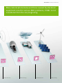
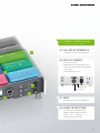
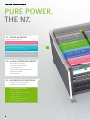
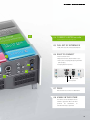
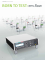
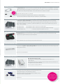
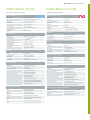
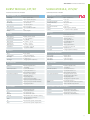
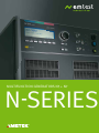
MULTIFUNCTION GENERATORS N5 + N7 N-SERIES the N-Series > MULTIFUNCTION GENERATORS Ignore EMC early pay the price later: OVERVIEW. Telecommunications 2 Components & Safety Industrial electronics the N-Series > MULTIFUNCTION GENERATORS Many natural phenomena and those caused by electronic equipment result in serious EMC problems, if EMC is not considered from the very beginning. Broadcast electronics Medical technology Residential electronics Renewable energy 3 the N-Series > MULTIFUNCTION GENERATORS THE WHOLE WORLD HAS STANDARDS. WE HAVE A SYSTEM. 4 the N-Series > MULTIFUNCTION GENERATORS The standards — are you familiar with all of them? Whether basic standard, generic standard, or product family standard — stipulated by law or demanded from the manu facturer: EM TEST has integrated all of them. Take advantage of the EM TEST test system. It knows what’s what and focuses specifically on your requirements. burst UU IEC/EN 61000-4-4 – Fast transients, bursts UU tt tt Spike Spike tt Burst Burst Switching operations of inductive loads result in interferences in supply networks. The fast, low-energy interference pulses are simulated with the generator and superimposed to the supply voltage and/or signal/data lines of the EUT. Surge UU t t t-circuit circuit current current IEC/EN 61000-4-5 – Surge voltages I I t t t t Open Opencircuit circuitvoltage voltage Atmospheric discharges may damage electronic devices. A qualified test must be performed to check resistance to such high-energy interferences. S hSohrot-circuit r t-circuitcurrent current POWER FAILURE UU IEC/EN 61000-4-11 – Voltage dips/short interruptions/voltage variations UU tt tt age tagevariations variations tt SShhoor tr ti ni nt et er rrur uppt itoi onn “Dips” is a term used to describe brownouts and voltage drops occurring in the supply network due to short-circuits or by sudden large changes of connected loads. Voltage Voltagevariations variations ringwave IEC/EN 61000-4-12 – Interference resistance to damped oscillatory waves U t OCS OCS Switching operations in inductive circuits, short-circuits, or lightning strikes can cause oscillatory transients, also called ringwaves, in building installations. This affects power as well as signal/data and control lines. To check the immunity of such lines, the optional ringwave module is used. DAMPED OSCILLATORY MAGNETIC FIELD IEC/EN 61000-4-10 – Interference resistance to damped oscillatory magnetic fields U t OCS OCS This international standard refers to requirements for immunity to damped oscillatory magnetic fields as occur in l ow-voltage and high-voltage power supply systems. Telecom-surge IEC/EN 61000-4-5, CCITT, FTZ 12TR1 U Telecommunication networks are exposed to lightning strikes and their associated effects. All telecommunication systems linked with lines installed outdoors therefore require reliable protection which needs to be tested. t Open circuit voltage MAGNETIC FIELDS I 50/60 Hz Magnetfeld Magnetfeld 50/60 Hz Mag netic field Ma gnet i c field t U I Magnetic field t Ma gnet i c field t uit current t IEC/EN 61000-4-8 – Magnetic fields with a frequency of 50/60 Hz, IEC/EN 61000-4-9 – Pulsed magnetic fields Electronic devices and installations in residential and industrial areas can be affected by magnetic fields with low frequencies. Lightning strikes to buildings, antenna masts, and transient impacts due to faults in low-voltage, medium-voltage, and highvoltage systems can cause pulsed magnetic fields. These phenomena can be simulated with the generator and the magnetic field coil (optional), thereby providing interference resistance proof. Open circuit voltageshor t-circuit current 5 the N-Series > MULTIFUNCTION GENERATORS A THOUSAND WISHES, ONE SOLUTION ... 6 the N-Series > MULTIFUNCTION GENERATORS >Logical: Easy, intuitive operation >Relaxed: Possible to set all parameters even during the test >Direct: Select from standard test levels >Exact: Statistical test options (random distribution) >Viable: Long-term viability regardless of standards >More Standard parameters must be exceeded powerful: (high performance reserves) >Inclusive I: Integrated interfaces (IEEE, USB) >Inclusive II: Integrated measuring technology (measured I/U values in display and CRO connection) >Low cost: Very good price/performance ratio >Exemplary: EM TEST service with accredited calibration labs 7 the N-Series > MULTIFUNCTION GENERATORS MODULAR ALL-IN-ONE ALL-ROUND TALENT! THE UCS 500N SERIES. 8 the N-Series > MULTIFUNCTION GENERATORS We present the compact and most powerful EM TEST test system of all times. Be ready for the future. For the best future of all times. 9 the N-SerieS > MULTIFUNCTION GENERATORS COMpACT pOWER. ThE N5. 01 MODULAR DESIGN Up to 5 modules in one unit: SURGE MODULE WITH 5,000 V, 1.2 µs/50 µs | 8 µs/20 µs 08 BURST/EFT MODULE WITH 5,500 V, 5 ns/50 ns | 1 MHz POWER FAIL MODULE WITH 300 V MAGNETIC FIELD, 1,000 A/m | 2,200 A/m 05 + OPTIONAL TSURGE MODULE 5,000 V, 10 µs/700 µs 02 em.flow OpERATING CONCEpT > Extremely easy to operate > Possible to set all parameters even during the test > Select directly from standard test levels > Statistical test options > Predefined tests 03 hIGh-RESOLUTION DISpLAy > Integrated measuring technology > Integrated I/U measurement OUR INNOVATIONS: > Displays I/U values > Displays surge voltages and current during surge test > Magnetic field test: Easy configuration and automatic parameter calculation 10 03 the N-SerieS > MULTIFUNCTION GENERATORS 04 CURRENT LIMITER em.safe > EUT protection during surge test 07 05 FULL SET OF INTERFACES > USB, IEEE 488, CN, analog input/outputs 06 EASy TO CONNECT > External motor variac > Magnetic field coil, IEC/EN 61000-4-8/-9 > Three-phase coupling/decoupling networks (burst/surge) 01 > Coupling filter for I/O lines 06 > Safety circuit > Warning lamps 04 02 07 pRICE Never before was so much so affordable! 08 VIABLE IN ThE FUTURE The device can be retrofitted and the soft ware upgraded. When EM TEST per forms the calibrations, an extended warranty is provided. 11 the N-SerieS > MULTIFUNCTION GENERATORS pURE pOWER. ThE N7. 08 01 MODULAR DESIGN Up to 6 modules in one unit: SURGE MODULE WITH 7,000 V, 1.2 µs/50 µs | 8 µs/20 µs BURST/EFT MODULE WITH 5,500 V, 5 ns/50 ns | 1 MHz POWER FAIL MODULE WITH 300 V 05 MAGNETIC FIELD, 1,000 A/m | 3,000 A/m + OPTIONAL RINGWAVE MODULE 6,000 V, 100 kHZ + OPTIONAL TSURGE MODULE 7,000 V, 10 µs/700 µs 02 em.flow OpERATING CONCEpT > Extremely easy to operate > Possible to set all parameters even during the test > Select directly from standard test levels > Statistical test options > Predefined tests 03 hIGh-RESOLUTION DISpLAy > Integrated measuring technology > Integrated I/U measurement OUR INNOVATIONS: > Displays I/U values > Displays surge voltages and current during surge test > Magnetic field test: Easy configuration and automatic parameter calculation 12 03 the N-SerieS > MULTIFUNCTION GENERATORS 07 04 CURRENT LIMITER em.safe > EUT protection during surge test 05 FULL SET OF INTERFACES > USB, IEEE 488, CN, analog input/outputs 06 EASy TO CONNECT 01 > External motor variac > Magnetic field coil, IEC/EN 61000-4-8/-9 > Three-phase coupling/decoupling networks 06 (burst/surge) > Coupling filter for I/O lines 04 02 > Safety circuit > Warning lamps 07 pRICE Never before was so much so affordable! 08 VIABLE IN ThE FUTURE The device can be retrofitted and the soft ware upgraded. When EM TEST per forms the calibrations, an extended warranty is provided. 13 the N-Series > MULTIFUNCTION GENERATORS BORN TO TEST: em.flow 14 the N-Series > MULTIFUNCTION GENERATORS Does not shy away from any type of test – the UCS 500N-series Experience the em.flow: More efficient testing. Use stan dard and guideline libraries to quickly compile and start test sequences. Becoming one with the device — because it is easy. And easy is brilliant. Still have some wishes? 15 the N-SerieS > MULTIFUNCTION GENERATORS SIMpLy GET GOING! WITh em.flow Comfortable one glance info: The multifunction display makes you a test champion. Easy navigation, right to the target! This is how working is fun. YOur ChOiCe NOTHING BUT CLARITY For example, if you decided to carry out a burst test, use the function keys next to select either Quickstart, standard test routines, or user test routines. F1 F2 F3 F4 F5 F6 F7 QuiCKStArt: NOthiNg iS FASter! THE MOST IMPORTANT SETTINGS ARE ALREADY PREDEFINED > All generator parameters at a single glance > Immediate test start > Each parameter can be changed during the test F1 F2 F3 F4 F5 F6 F7 StANDArD PrOgrAMS THE MOST COMPREHENSIVE STANDARD PROGRAM OF THE INDUSTRY Instead of the Quickstart, you can also load any current standard from the integrated standards and guideline library and easily conduct tests based on the preset parameters. Of course, regular library updates are available from EM TEST. F1 F2 F3 F4 F5 F6 F7 uSer PrOgrAMS CHOOSE FROM PRE-CONFIGURED TEST PARAMETERS you prefer your own test sequences? No problem: The UCS offers comprehensive setting options. Just select what you want. F1 16 F2 F3 F4 F5 F6 F7 the N-SerieS > MULTIFUNCTION GENERATORS Easy as pie: Thanks to the EM TEST operating concept utili zing function keys and control dials, handling the device is unbelievably simple. This much ease of use requires no additional explanations... 17 the N-SerieS > MULTIFUNCTION GENERATORS ThREE INNOVATIONS. MADE By EM TEST. 1ST INNOVATION: CURRENT LIMITER em.safe em.safe – AS Sure AS DeAth AND tAXeS CONFIGURABLE CURRENT LIMITER Reliable testing with em.safe. An EUT is easily overloaded. And if this EUT is also a prototype, costs will rise in addition to the time delay as well. F1 F2 F3 F4 F5 F6 F7 F1 F2 F3 F4 F5 F6 F7 em.safe – PROTECTION FOR YOUR EUT you probably do not pay attention to such details in the course of your everyday work routine but check to see how many devices actually feature such a protective function. you will be surprised. Without em.safe With em.safe 2ND INNOVATION: I/U DISpLAy i/u DiSPLAY CURRENT AND VOLTAGE DISPLAY Information about current and voltage levels is important to you as user when performing surge tests. Of course, you also want these values depicted quickly and whenever you need them. The UCS is ready to satisfy your demands. 18 the N-SerieS > MULTIFUNCTION GENERATORS Of course, all these innovations are found in both, the N5 and the N7 – no doubt. 3RD INNOVATION: MAGNETIC FIELD TESTS eXAMPLe: MAgNetiC FieLD teSt F1 F2 F3 F4 SeLeCtiNg the MAgNetiC FieLD PrOgrAM OF StANDArDS F5 F6 F7 SIMPLY SWITCH ON AND SELECT THE RIGHT MODULE The coil and transformer correction factor must be considered when performing the magnetic field test. The complexity of this process is no longer a problem because the UCS does the calculating for you! Use the F4 function key to access the magnetic field menu directly. F2 F3 F4 F5 ADJUSTING THE TEST PARAMETERS One more step and you already have a choice of the preset program of standards for magnetic fields (F2) or the easy magnetic field setup (F7). F6 F2 A F3 F4 F5 F6 F7 B SIMPLIFIED MAGNETIC FIELD TESTING The parameters of the standard, level 1 to level 5, are already preset and can be selected immediately with the rotary selector. B SettiNg COiL AND trANSFOrMer FACtOr A ADJuStiNg the PArAMeterS OF the StANDArD F1 F1 F7 F1 F2 F3 F4 F5 F6 F7 ADJUSTING THE TEST PARAMETERS you select, the UCS calculates. Formula compilation tables and pocket calculator stay on the shelf. That’s what we call “easy”! OLD MANUAL METHOD: COIL FACTOR (FCoil) FCoil = h Field [A/m] I Coil [A] TRANSFORMER FACTOR (FTrafo) FTrafo = I Coil [A] U prim Transformer [V] 19 the N-Series > MULTIFUNCTION GENERATORS CUSTOMIZED FOR EVERY TEST: the iec.control 20 the N-Series > MULTIFUNCTION GENERATORS Our software concept is consistently user-friendly. Nothing is simpler — the same applies to the device. Just switch your computer on. And then – here we go! Even more functions with iec.control 21 the N-Series > MULTIFUNCTION GENERATORS iec.control – the testware. MANUFACTURER STANDARDS: BE IN THE KNOW WITH ONE OF THE LARGEST LIBRARY OF STANDARDS AND GUIDELINES STANDARD SELECTION > Selection based on basic/generic/product standards > Product standards are divided into categories to provide a clearer overview > Standards can be adjusted/changed > Password protection for EASY/EXPERT mode APPLICATION SELECTION > Easy to navigate Desktop view of all functions > Quickstart by selecting standard, application, or test pulse directly > Functions such as TEST, LINK, or REPORT files are available > Status bar depicts all of the important information > All functions also selectable from the MENU 22 the N-Series > MULTIFUNCTION GENERATORS Master all processes with iec.control. At a single glance. Never before was it this easy to generate test sequences. And every thing can be configured or modified with the computer. iec.control Software SPECIFIC TEST SEQUENCES: EASILY GENERATE AND SAVE YOUR OWN TEST SPECIFICATIONS DETAIL SETTINGS > Informal test pulse graphic with parameter description > Directly selectable standard level > Any parameter setting in SPECIAL mode > Control buttons effectively placed at always the same position > Never loose sight of the test time LINK FILE GENERATOR > Individual TEST files are combined into LINK files > LINK files can be repeated as often as desired using the event counter > The incurred total test time is calculated and displayed > All files can be saved to and loaded from the computer network > Pause times and test information can be inserted between the individual test routines > A comment can be entered after each test, which is then inserted automatically into the test report 23 the N-SerieS > MULTIFUNCTION GENERATORS MEASURING EQUIpMENT: INTEGRATION AND MANAGEMENT OF EXTERNAL MEASURING AND TESTING INSTRUMENTS MeASuriNg iNStruMeNt SeLeCtiON > Any kind of measuring instruments and oscilloscopes can be integrated using IEEE/GpIB > Testing instruments can thus monitor the EUT > Oscilloscopes can integrate a plot to monitor the pulse > Alarm levels can be configured for the optimal measuring sequence control > EUT monitoring is realized with the logged measured values and trigger the fail function in an emergency to terminate the test teSt SeQueNCe > Display of all relevant data during the test > A clear overview of all finished and still pending tests at all times > Measuring instrument information is depicted and alarms are identified > All data are prepared in the background for documentation purposes > The status bar informs which test simulator is currently active > Continuous logging of the measured values during testing and also depicted in the test window. The plot with the last pulse of the test is prepared during the pulse monitoring and then inserted into the test report if desired. 24 the N-SerieS > MULTIFUNCTION GENERATORS From the first standard selection to the finished test report, iec.control provides with everything you could wish for from an easy to use EMC test software. A brilliant match for the EM TEST hardware. iec.control Software REpORT GENERATION: EASILy MANAGE, pRINT OUT TESTS AND UpDATE STANDARDS rePOrt geNerAtiON > Layout templates for individual test report designs > Complete documentation acc. to DIN EN ISO/IEC 17025 > Clearly structured overview due to graphic with parameter configuration > If desired, documents are immediately formatted as RTF files > The test report is generated automatically during the test and is finished as soon as the test is completed > Complete test report with plot mapping The test report template can be customized and features your own company logo teSt rePOrt 25 the N Series > MULTIFUNCTION GENERATORS extendedCAPAbilities: ACCESSORIES 26 the N-SerieS > MULTIFUNCTION GENERATORS MAgNetiC FieLD COiL The magnetic field coil can be used for more than just standard tests. When combined with the UCS 500N5/N7, it is possible to simulate any field strengths up to 1,000 A/m. The magnetic field coil (1 m x 1 m) with a 4 cm² cross-section meets the requirements tic Mag ne n be il ca field co ed by turn 3 60 ° of IEC 61000-4-8 Ed. 2:2009 and IEC/EN 61000-9. A special model with wheels is available as an option. Type MS 100N: 1,000 A/m, pulsed up to 3,200 A/m - MC 2630 current transformer for magnetic fields up to 40 A/m acc. to IEC/EN 61000-4-8 - MC 26100 current transformer for magnetic fields up to 1,000 A/m acc. to IEC/EN 61000-4-8 three-PhASe COuPLiNg NetwOrKS FOr burSt AND Surge PuLSeS ACC. tO ieC 61000-4-4/-5, eN 61000-4-4/-5 The three-phase coupling network CNi 503 is a combination of burst and surge coupling filters and serves to superimpose the interference pulses over the three phase power supplies. Coupling networks of 16 A to 200 A/AC per phase can be provided. Special versions are available, e.g., 690 VAC (L-L) to 100 A and 1,000 VDC / to 63 A for the area of renewable energies (solar technology – inverter technology). Series CNI 503 to 5 kV: Type: CNI 503Ax, 3 x 480 V / 16 A, 32 A, 63 A*, 100 A*, 200 A* Series CNI 503 to 7 kV: Type: CNI 503Bx, 3 x 480 V / 16 A, 32 A, 63 A*, 100 A*, 200 A* (ANSI / IEC couplings) Series CNI 501/503 to 7 kV: 3 x 690 VAC / max.100 A and 1,000 VDC / max. 63 A * delivered in rack e AND h FieLD SeNSOrS tO trACK DOwN iNterFereNCe reSiStANCe FLuCtuAtiONS e and h field sensors help users find weak points as early as the development phase resulting in a considerable cost saving. Application areas range from circuitry to enclosure development. Type ITP: Broadband sensor set for E fields, type ITP/H: Field sensors for H fields CAPACitive COuPLiNg CLAMP The standardized capacitive coupling clamp (type hFK) makes it possible to couple burst pulses onto control and signal lines without galvanic connection. Type HFK: Acc. to IEC/EN 61000-4-4 trANSFOrMerS AND vAriACS Auto transformers and motor variacs Auto transformers are optionally available for voltage dips and interruptions acc. to IEC/EN 61000-4-11. Various optional motor variacs are available to support voltage variations (IEC/EN 61000-4-11) and magnetic field tests (IEC/EN 61000-4-8). Type V 4780, Type V 4780S2, Type MV 2616 CALibrAtiON Kit Our calibration kit to verify the generator at the coaxial output as well as at the coupling network output acc. to IEC/EN61000-4-4, Edition 2. The calibration kit includes the load resistors KW 50 and KW 1000 as well as an adapter to measure the coupling network Type CA EFT Kit pLEASE VISIT www.emtest.com FOR EVEN MORE ACCESSORIES 27 the N-SerieS > MULTIFUNCTION GENERATORS UCS 500N5 TEChNICAL DATA 28 the N-Series > MULTIFUNCTION GENERATORS Burst-modul, EFT/N5 Surge-Modul, VCS/N5 Electrical fast transient simulator Combination wave simulator BURST MODULE, EFT/N5 Test voltage MODUL SURGE, VCS/N5 200 V – 5,500 V ± 10%, Voltage (o.c.) 160 V – 5,000 V ± 10% 100 V – 2,750 V ± 10% (50 T) Rise time 1.2 µs ± 30% Pulse shape 5/50 ns at 50 T and 1,000 T Decay time to half value 50 µs ± 20% Rise time (tr) 5 ns ± 30% at 50 T, Current (s.c.) Max. 2,500 A ± 10% 5 ns ± 30% at 1,000 T Rise time 8 µs ± 20% 50 ns ± 30% at 50 T, Decay time to half value 20 µs ± 20% 50 ns –15/+100 ns at 1,000 T Polarity Positive/negative/alternating Source impedance 50 T Counter 1 – 30,000 or endless, adjustable Polarity Positive/negative Pulse duration TRIGGER (BURST) TRIGGER Pulse trigger Automatic, manual, external Pulse trigger Automatic, manual, external Synchronization 0° – 360°, resolution 1° Synchronization 0° – 360°, resolution 1° Repetition rate Max. 1 Hz (1 s – 999 s) (16 – 500 Hz) Burst duration (td) td = 0.10 ms – 999 ms Repetition rate (tr) tr = 10 ms – 9,999 ms Burst frequency f = 0.1 kHz – 1,000 kHz Test duration T = 0:01 min. – 99:59 min. T > 99:59 min. --> infinite Via 50 T coaxial Coupling modes L, N, PE; all combinations DUT supply AC: 300 V/16 A; 50/60 Hz DC: 300 V/16 A 5 V trigger signal for oscilloscope TEST ROUTINES Parameter adjustable online, easy handling Standard test routines Acc. to IEC/EN 61000-4-4 Acc. to IEC/EN 61000-6-1/-2 Manual standard test routine User-defined test routines Via HV connectors, Zi = 2 T Couplings Line to line Line to ground (PE) DUT supply CRO trigger Direct Quickstart Direct Changing voltage after T CRO Û monitor 10 Vp/5,000 V CRO Î monitor 10 Vp/2,500 A Peak voltage 5,000 V in LC display Peak current 2,500 A in LC display TEST PROCEDURES Quickstart Frequency sweep (constant burst duration) Acc. to IEC/EN 61000-4-5 Acc. to IEC/EN 61000-6-1/-2 Manual standard test routines User-specific test routines Changing coupling after n pulses Changing voltage after T Changing phase angle after n pulses Pulsed magnetic field Acc. to IEC/EN 61000-4-9 Test level 100, 300 and 1,000 A/m, test level Changing polarity after T ACCESSORIES (BURST) Parameter adjustable online, easy handling Standard test routines Frequency sweep (single burst) Frequency sweep (constant pulse number) 5 V trigger signal for oscilloscope MEASURING EQUIPMENT Synchronous burst triggering Random burst release HFK AC: 300 V/16 A; 50/60 Hz DC: 300 V/16 A OUTPUTS CRO trigger OUTPUTS variable adjustable using Quickstart ACCESSORIES (COUPLING NETWORKS) Capacitive coupling clamp Acc. to IEC/EN 61000-4-4 KW 50 100:1 load resistor, 50 T KW 1000 500:1 load resistor, 1,000 T CA EFT kit Calibration kit for pulse verification CNV504N Coupling network for 4 signal/data lines acc. to IEC/EN 61000-4-5 CNV508N Coupling network for 8 signal/data lines acc. to IEC/EN 61000-4-5 Consists of KW 50, KW 1000 and adapters A6dB 6 dB attenuator, 50 T ITP Field sensor kit to generate electrical fields ITP/H Field sensor kit to generate magnetic fields 29 the N-Series > MULTIFUNCTION GENERATORS POWER FAIL MODULE PFS/N5 TELECOM SURGE MODULE* Power fail simulator Telecom surge simulator – TSurge5 POWER FAIL MODULE, PFS/N5 TSURGE5 MODULE Channel PF1/PF2 AC voltage: max. 300 V Test voltage 160 V – 5,000 V ± 10% AC current: max. 16 A Storage capacitor 20 uF DC voltage: max. 300 V Polarity Positive, negative, alternating DC current: max 16 A (IEC/EN 61000-4-29) Counter 1 – 30,000 or infinite, adjustable acc. to ITU and ETSI recommendations Frequency 16 Hz – 500 Hz Switching time < 5 us at 100 T resistive load Rise time 10 µs ± 30% Inrush current > 500 A Pulse duration 700 µs ± 20% Protection Both channels short-circuit protected TRIGGER Trigger Automatic, manual, external Synchronization 0° – 360°, resolution 1° (16 – 500 Hz) Repetition rate 10 ms – 9,999 s Test time 20 µs – 9,999 s OUTPUTS DUT terminals L, N and PE CRO trigger 5 V trigger signal for oscilloscope MEASURING EQUIPMENT DUT voltage In display DUT current In display MON V Measuring DUT voltage with integrated divider 100:1 MON I Measuring DUT current 10 mV/A; max. 1,000 A TEST ROUTINES Parameter adjustable online, easy handling Standard test routines Acc. to IEC/EN 61000-4-11 for AC supply Acc. to IEC/EN 61000-4-29 for DC supply Acc. to IEC/EN 61000-6-1, -6-2 man. test routines Changing phase angle after n events Changing event duration after n events Inverse mode Acc. to IEC/EN 61000-4-8 Test level 1, 3, 10 and 30 A/m with external current transformer MC2630 Test level 100, 300 and 1,000 A/m with current transformer MC26100 ACCESSORIES V4780 Auto transformer with taps acc. to IEC/EN 61000-4-11 Ed. 2 V4780 S2 Auto transformer with automatically switched taps acc. to IEC/EN 61000-4-11 Ed.2 MV2616 Motor variac (0 – 260 V, 16 A) MS100N Magnetic field coil, 1 m x 1 m MC2630 Current transformer for magnetic fields up to 30 A/m MC26100 Current transformer for magnetic fields up to 1,000 A/m CA PFS Calibration box to verify the inrush current acc. to IEC/EN 61000-4-11 30 720 µs ± 20% Output current 6 A – 125 A (short-circuit) Rise time 5 µs ± 30% Pulse duration 320 µs ± 20% Acc. to IEC/EN 61000-4-5 Rise time 6,5 µs ± 30% Pulse duration 700 µs ± 20% Output current 6 A – 125 A (short-circuit) Rise time 4 µs ± 20% Pulse duration 300 µs ± 20% TRIGGER Trigger Automatic, manual, external Repetition rate Max. 0.5 Hz (2 s – 999 s) OUTPUTS (TELECOM SURGE) Acc. to ITU For 2-conductor T1/T2, 25 T each Acc. to FCC part 68 For 2-conductor T1/T2, 25 T each Acc. to IEC/EN 61000-4-5 For 4-conductor T1, T2, T3 and T4, 100 T each CNV 504S1 Coupling filter for 4 telecommunication lines (IEC/EN 61000-4-5) CNV 508S1 Coupling filter for 8 telecommunication lines (IEC/EN 61000-4-5) Voltage variations Controlling external variacs 50/60 Hz magnetic field 9 µs ± 30% Pulse duration OPTIONS Quickstart User-specific test routines Acc. to FCC part 68, pulse B Rise time *Optionally available the N-Series > MULTIFUNCTION GENERATORS GENERAL DATA CONNECTIONS/PORTS Serial interface USB Parallel interface IEEE 488, addresses 1 – 30 Analog output 0 – 10 VDC to control external transformers CN interface 15-pin SubD connector to control external couplers Fault inputs DUT monitoring via Fail 1 and Fail 2 input (each 1) DIMENSIONS AND WEIGHTS Dimensions 19"/3 HU, 19"/6 HU (with TSurge5 module) Weight Approx. 25 kg mains Line voltage 115/230 V AC (+10%/–15%) Power Approx. 75 W Frequency 50/60 Hz Fuses 2xT2A (230 V)/2xT4A (115 V) SAFETY Safety standard IEC/EN 61010 Safety circuit Control input (24 VDC) Warning lamps Potential-free (230 V / 6 A) SCOPE OF DELIVERY Power cable Acc. to destination country Cable to DUT supply Acc. to destination country DUT adapter Acc. to destination country User manual Calibration certificate USB cable (USB A/B 3 m) Control software iec.control Accessories CNI 503Ax 3-phase coupling network Acc. to IEC/EN 61000-4-4 and 4-5 Up to 200 A per phase CNI 508N1 Coupling network for fast communication lines acc. to IEC/EN 61000-4-5. iec.control 1 Control and documentation software Incl. standard test routines and report options Integration of any measuring equipment and oscilloscopes using IEEE-GPIB commands. Information about delivery scope, design, performances, capacities, dimensions, and weights correspond with the data available at the time of printing. Subject to change. © EM TEST 2010 31 the N-SerieS > MULTIFUNCTION GENERATORS UCS 500N7 TEChNICAL DATA 32 the N-Series > MULTIFUNCTION GENERATORS BURST MODULE, EFT/N7 Electrical fast transient simulator BURST MODULE, EFT/N7 Test voltage SURGE MODULE, VCS/N7 Combination wave simulator SURGE MODULE, VCS/N7 200 V – 5,500 V ± 10%; Voltage (open) 250 V – 7,000 V ± 10% 100 V – 2,750 V ± 10% (50 T) Rise time 1.2 us ± 30% Pulse shape 5/50 ns at 50 T and 1,000 T Decay time to half value 50 µs ± 20% Rise time (tr) 5 ns ± 30% at 50 T, Current (short-circuit) Max. 3,500 A ± 10% 5 ns ± 30% at 1,000 T Rise time 8 µs ± 20% 50 ns ± 30% at 50 T, Decay time to half value 20 µs ± 30% 50 ns –15/+100 ns at 1,000 T Polarity Positive, negative, alternating Source impedance 50 T Counter 1 – 30,000 or endless, adjustable Polarity Positive/negative Burst range (td) TRIGGER OUTPUTS Direct Via HV connectors, Zi = 2 T Couplings Acc. to IEC/EN 61000-4-5 Burst triggering Automatic, manual, external Synchronization 0° – 360°, resolution 1° Line to line with 2 T (16 – 500 Hz) Line to ground with 12 T Burst duration td = 0.10 ms – 999 ms Acc. to ANSI/IEEE C62.41 Repetition rate tr = 10 ms – 9,999 ms Line to line with 2 T Burst frequency f = 0.1 kHz – 1,000 kHz Test duration T = 0:01 min – 99:59 min Line(s) to ground with 2 T DUT supply CRO trigger OUTPUTS AC: 300 V / 16 A; 50/60 Hz DC: 300 V / 16 A T > 99:59 min --> infinite 5 V trigger signal for oscilloscope MEASURING EQUIPMENT Direct Via 50 T coaxial Coupling modes L, N, PE; all combinations CRO Û monitor 10 Vp at 7,000 V DUT supply AC: 300 V / 16 A; 50/60 Hz CRO Î monitor 10 Vp at 3,500 A DC: 300 V / 16 A Peak voltage 7,000 V in LC display 5 V trigger signal for oscilloscope Peak current 3,500 A in LC display CRO-Trigger TEST ROUTINES Quickstart TEST ROUTINES Parameter adjustable online, Quickstart easy handling Standard test routines Acc. to IEC/EN 61000-4-4, easy handling Standard test routines Acc. to IEC/EN 61000-6-1/-2 Synchronous burst triggering Manual standard test routines User-specific test routines Changing polarity after n pulses Random burst release Changing coupling after n pulses Changing voltage after T Changing voltage after T Frequency sweep (single burst) Changing phase angle after n pulses Frequency sweep (constant pulse number) Magnetic field, Acc. to IEC/EN 61000-4-9 Frequency sweep (constant burst duration) pulsed Test level 100, 200 and 1,000 A/m, test level Changing polarity after T ACCESSORIES HFK Acc. to IEC/EN 61000-4-5 Acc. to IEC/EN 61000-6-1/-2 Manual standard test routines User-defined test routines Parameter adjustable online, variable adjustable using Quickstart ACCESSORIES (COUPLING NETWORKS) Capacitive coupling clamp CNV504N Acc. to IEC/EN 61000-4-4 KW 50 100:1 load resistor, 50 T KW 1000 500:1 load resistor, 1,000 T CA EFT Kit Calibration kit for pulse verification consisting Coupling network for 4 signal/ data lines acc. to IEC/EN 61000-4-5 CNV508N Coupling network for 8 signal/ data lines acc. to IEC/EN 61000-4-5 of KW 50, KW 1000 and adapters A6dB 6 dB attenuator, 50 T ITP Field sensor kit to generate electrical fields ITP/H Field sensor kit to generate magnetic fields 33 the N-Series > MULTIFUNCTION GENERATORS POWER FAIL MODULE PFS/N7 RINGWAVE MODULE* RWG/N7 Power fail simulator Oscillatory wave simulator POWER FAIl MODULE, PFS/N7 RINGWAVE MODULE, RWG/N7 Channel PF1/PF2 AC voltage: max. 300 V Test voltage 250 V – 6,000 V ± 10% AC current: max. 16 A Voltage Pulse shape (open circuit) DC voltage: max. 300 V Rise time (1st peak) 0.5 µs ± 30% DC current: max 16 A (IEC/EN 61000-4-29) Oscillation frequency 100 kHz ± 20% Frequency 16 Hz – 500 Hz Decay values Peak 2 to Peak 1 = 40 – 110% Switching time < 5 us at 100 T resistive load Inrush current > 500 A Protection Both channels short-circuit protected TRIGGER Trigger Automatic, manual, external Synchronization 0° – 360°, resolution 1° (16 – 500 Hz) Repetition rate 10 ms – 9,999 s Test time 20 µs – 9,999 s OUTPUTS DUT connection L, N and PE CRO trigger 5 V trigger signal for oscilloscope MEASURING EQUIPMENT DUT voltage In display DUT current In display MON V Measuring DUT voltage with integrated divider 100:1 MON I Measuring DUT current; 10 mV/A; max. 1,000 A TEST ROUTINES Quickstart Parameter adjustable online, Acc. to IEC/EN 61000-6-1, 6-2 man. test routines Voltage variation, external variac control Changing phase angle after n events, Changing event duration after n events, Inverse mode 50/60 Hz magnetic field Acc. to IEC/EN 61000-4-8 Test level 1, 3, 10 and 30 A/m with external current transformer MC2630 Test level 100, 300 and 1,000 A/m with external current transformer MC26100 ACCESSORIES V4780 Auto transformer with taps acc. to IEC 61000-4-11 Ed. 2 V4780 S2 Auto transformer with automatically switched taps acc. to IEC 61000-4-11 Ed.2 MV2616 Motor variac (0 – 260 V, 16 A) MS100N Magnetic field coil 1 m x 1 m MC2630 Current transformer for magnetic fields up to 30 A/m MC26100 Current transformer for magnetic fields up to 1,000 A/m CA PFS Calibration box to verify the inrush current acc. to IEC/EN 61000-4-11 34 Pulse shape (short-circuit) Rise time <= 1.0 µs Oscillation frequency 100 kHz ± 20% Source impedance 12 T and 30 T Peak current Acc. to selected source impedance Polarity Positive/negative TRIGGER Pulse triggering Automatic, manual, external Synchronization 0° – 360°, resolution 1° Repetition rate Max. 1 Hz (1 s – 999 s) OUTPUTS Direct Via HV connector Coupling types L, N, PE; line to line and line to ground DUT supply AC: 300 V/16 A, 50/60 Hz DC: 300 V/16 A CRO trigger 5 V trigger signal for oscilloscope TEST ROUTINES Parameter adjustable online, easy handling Standard test routines Acc. to ANSI/IEEE C62.41 Acc. to IEC/EN 61000-4-12 Acc. to IEC/EN 61000-4-11 for AC supply Acc. to IEC/EN 61000-4-29 for DC supply User-specific test routines Peak 4 to Peak 3 = 40 – 80% Current Quickstart easy handling Standard test routines Peak 3 to Peak 2 = 40 – 80% *Optionally available the N-Series > MULTIFUNCTION GENERATORS TELECOM SURGE MODULE* GENERAL data Telecom surge simulator – TSurge7 TSURGE MODULE, TSURGE7 CONNECTIONS/PORTS Test voltage (open) 250 V – 7,000 V ± 10% Serial interface USB Storage capacitor 20 uF Parallel interface IEEE 488, addresses 1 – 30 Polarity Positive, negative, alternating Analog output 0 – 10 VDC to control Counter 1 – 30,000 or infinite, adjustable acc. to ITU and ETSI recommendations Rise time 10 µs ± 30% Pulse duration 700 µs ± 20% external transformers CN interface 15-pin SubD connector to control external coupling networks Fail inputs DUT monitoring via Fail1 and Fail2 inputs Acc. to FCC part 68, pulse B Rise time 9 µs ± 30% Pulse duration 720 µs ± 20% Output current 6 A – 175 A (short-circuit) Rise time 5 µs ± 30% Pulse duration 320 µs ± 20% Acc. to IEC/EN 61000-4-5 DIMENSIONS AND WEIGHTS Housing 19", 6 HU, L = 532 mm Weight Approx. 29 kg Mains Rise time 6.5 µs ± 30% Supply voltage 115/230 VAC +10%/–15% Pulse duration 700 µs ± 20% Power Approx. 75 W Output current 6 A – 175 A (short-circuit) Frequency 50/60 Hz Rise time 4 µs ± 20% Fuses 2 x T2A (230 V) or 2 x T4A (115 V) Pulse duration 300 µs ± 20% TRIGGER SAFETY Safety standard IEC/EN 61010 Trigger Automatic, manual, external Safety circuit Control input (24 VDC) Repetition rate Max. 0.33 Hz (3 s – 999 s) Warning lamps Potential-free (230 V/6 A) OUTPUTS SCOPE OF DELIVERY Acc. to ITU 2-conductor T1/T2, 25 T each Power cable Acc. to destination country Acc. to FCC part 68 2-conductor T1/T2, 25 T each Cable to DUT supply Acc. to destination country Acc. to IEC 61000-4-5 4-conductor T1/T2, 100 T each DUT adapter Acc. to destination country User manual OPTIONS CNV 504S1 Calibration certificate Coupling filter for 4 telecommunication lines (IEC/EN 61000-4-5) CNV 508S1 Coupling filter for 8 telecommunication lines (IEC/EN 61000-4-5) *Optionally available USB cable (USB A/B 3 m) Control software iec.control ACCESSORIES CNI 503Bx 3-phase coupling/decoupling networks Acc. to IEC/EN 61000-4-4/-5 as well as ANSI/IEEE C62.41 up to 200 A per phase CNI 508N1 Coupling network for fast communication lines acc. to IEC/EN 61000-4-5. iec.control Control and documentation software Incl. standard test routines and report options Integration of any measuring equipment and oscilloscopes using IEEE-GPIB commands. Information about delivery scope, design, performances, capacities, dimen sions, and weights correspond with the data available at the time of printing. Subject to change. © EM TEST 2010 35 the N-SerieS > MULTIFUNCTION GENERATORS EM TEST SERVICES: CUSTOMIZED SOLUTIONS FOR EVERy NEED. SERVICE & SUppORT: ALWAyS AVAILABLE COMPreheNSive ServiCe POrtFOLiO Our comprehensive professional service and support solutions leave nothing to be desired. Commissioning, briefings, updates, maintenance, and repair work are given high priority at EM TEST. Thanks to the outstanding infrastructure, an optimum service project management, and especially thanks to our highly qualified and moti vated employees, we literally achieve the highest level of EM TEST service quality. ACCREDITED CALIBRATION LABS: ABSOLUTE COMpLIANCE su ie s or d L a b o r at Co te A ccred i rePrODuCibLe, FASt & COMPeteNt re! The accredited EM TEST calibration laboratories in Reinach (Ch) and Kamen (D) perform competent, independent and n f SCS 114 r id e e f o reasonably priced calibrations according to nc DIN EN ISO/IEC 17025 as well as national and international standards. And not just for EM TEST products, but also for equipment from other manufacturers. And if you like also on site. EXTENDED WARRANTy: QUASI FOR FREE MOre wArrANtY? with PLeASure. Calibrations of EM TEST offer more. your EM TEST product will be checked on request and if necessary adjusted imme diately. We are so convinced of the quality of our products that the warranty time can be extended to 3 years by having calibrated the equipment at any of the accredited calibra tion laboratories of EM TEST during the 2year warranty period. hence, you’ll get 1 year warranty almost for free. 36 the N-Series > MULTIFUNCTION GENERATORS Contact us from anywhere in the world: www.emtest.com EMC TEST LAB: YOUR PRODUCT SUCCESS IS OUR MISSION PROFESSIONAL SUPPORT RIGHT FROM THE Beginning EM TEST assists you already on the development phase of your products with technical coaching and tangible mea sures such as layout optimization, design of devices and power supplys, grounding and shielding, microprocessor board design, and much more. Not only do we determine the interference potentials but we also simultaneously develop suitable interference suppression and elimination measures in cooperation with you, our customer. EMC SEMINARS & WORKSHOPS: success Can be learned EMC-knowledge for beginners und professionals Our EMC seminars and workshops are geared to our customer’s requirements in the fields of research, development and production. All EM TEST lecturers come exclusively from the practice and impart their knowlegde vividly and up close in a personal manner to the participants. Maximum know-how transfer and learning success are guaranteed. RENTAL EQUIPMENT: READY FOR EVERY TESTING DEMAND ALWAYS THE RIGHT TESTING INSTRUMENT Bridge long-term planned investments by renting the equipment you need for as long as you need it at EM TEST. We have a large pool of rental equipment, which is not only state of the art, but moreover fully compliant with all EMC testing requirements. With rental equipment from EM TEST you can respond promptly and flexibly to unexpected testing demands. Quickly and economically! 37 USA EM TEST USA > 9250 Brown Deer Road > San Diego > CA 92121 > USA Phone +1 (858) 699 1685 > Fax +1 (858) 458 0267 Internet www.emtest.com > E-mail [email protected] Germany EM TEST GmbH > Lünener Straße 211 > 59174 Kamen > Germany Phone +49 (0) 2307 26070-0 > Fax +49 (0) 2307 17050 Internet www.emtest.com > E-mail [email protected] China E & S Test Technology Limited > Rm 913, Leftbank No. 68 Bei Si Huan Xi Lu > Haidian District > Beijing 100080 > P.R. China Phone +86 (0) 1082676027 > Fax +86 (0) 1082676238 Internet www.emtest.com > E-mail [email protected] France EM TEST France > Le Trident - Parc des Collines > Immeuble B1 - Etage 3 36, rue Paul Cézanne > 68200 Mulhouse > France Phone +33 (0) 389 312350 > Fax +33 (0) 389 312355 Internet www.emtest.fr > E-mail [email protected] Poland EM TEST Polska > ul. Ogrodowa 31/35, 00-893 Warszawa > Poland Phone +48 (0) 518 643512 > Fax +48 (0) 518 643512 w. 4 Internet www.emtest.com/pl > E-mail [email protected] Republic of Korea (South Korea) EM TEST Korea Limited > RM 405 > WooYeon Plaza > #986-8 YoungDeok-dong > Giheung-gu > Yongin-si > Gyeonggi-do > Korea Phone +82 (31) 2168616 > Fax +82 (31) 2168618 Internet www.emtest.co.kr > E-mail [email protected] www.cyclos-design.de V.04/13 Switzerland EM TEST (Switzerland) GmbH > Sternenhofstrasse 15 > 4153 Reinach > Switzerland Phone +41 (0) 61 7179191 > Fax +41 (0) 61 7179199 Internet www.emtest.ch > E-mail [email protected]