1
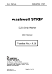
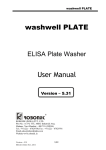
User Manual A.D. SHAKE, RT A.D. SHAKE , RT 21.2.2011/ Version 01 Page 1 of 28 User Manual A.D. SHAKE, RT TABLE OF CONTENTS Installation cum Warranty Certificate (Original) ..............................................................3 1. GENERAL INFORMATION ......................................................................................3 1.1 WARRANTY INFORMATION:........................................................................................ 3 1.2 TECHNICAL SERVICE:................................................................................................. 3 1.3 CONTACTS: ................................................................................................................ 3 2. GENERAL SAFETY WARNINGS .............................................................................3 2.1 DANGER – WARNINGS SYMBOLS: ................................................................................ 3 2.2 USE OF THE INSTRUMENT: .......................................................................................... 3 3. INTRODUCTION .......................................................................................................3 3.1 SPECIAL FEATURES: ................................................................................................... 3 3.2 SPECIFICATIONS:........................................................................................................ 3 4. PACKING, TRANSPORT AND STORAGE ...............................................................3 4.1 GENERAL WARNINGS:................................................................................................. 3 4.2 PACKING:................................................................................................................... 3 4.3 INSTRUMENT TRANSPORTATION:................................................................................. 3 4.4 STORAGE OF THE INSTRUMENT: .................................................................................. 3 5. INSTRUMENT DESCRIPTION..................................................................................3 5.1 PERSPECTIVE VIEW: ................................................................................................... 3 A) FRONT VIEW ............................................................................................................... 3 B) KEYBOARD: ................................................................................................................ 3 C) REAR VIEW................................................................................................................. 3 6. Installation procedure and verification criteria..............................................................3 6.1 UNPACKING INSTRUCTIONS: ....................................................................................... 3 6.2 PLACING THE INSTRUMENT:........................................................................................ 3 6.3 POWER SUPPLY REQUIREMENTS: ................................................................................. 3 6.4 PROTECTIVE GROUNDING:.......................................................................................... 3 6.5 START UP INSTRUCTIONS:........................................................................................... 3 7. PRECAUTIONS..........................................................................................................3 8. GENERAL KEY AND OPERATION .........................................................................3 8.1 SHAKE KEY: ............................................................................................................ 3 8.2 TIMER KEY: ............................................................................................................. 3 8.3 ENTER KEY:............................................................................................................. 3 8.4 TEMPERATURE KEY: ............................................................................................. 3 9. SAFETY CLEARANCE CERTIFICATE: ...................................................................3 10. SPARE PARTS .........................................................................................................3 10.1 SPARE PART LIST ...................................................................................................... 3 10.2 ORDERING SPARE PARTS: ......................................................................................... 3 11. Packing list ................................................................................................................3 21.2.2011/ Version 01 Page 2 of 28 User Manual A.D. SHAKE, RT The contents of this manual with all figures, tables and graphics are intellectual property of APDia. Unauthorized commercial or non-commercial excerption or copying of contents and use of this manual (in total or in parts) are strictly forbidden unless the editor gives written permission for it. The manual describes APDia and its software. This manual was written and produced with the utmost care. However, errors cannot be fully excluded. APDia does not take any responsibility and accepts no liabilities of any kind that may occur because of errors in the manual. 21.2.2011/ Version 01 Page 3 of 28 User Manual A.D. SHAKE, RT Installation cum Warranty Certificate (Original) (2 copies, Original for APDia and duplicate for Customer) ONE-YEAR WARRANTY FROM THE DATE OF INSTALLATION Name of the Customer : Complete Address : (Includes Postal Address, Tel No. and E-mail address) Serial No. : Date of Installation : Invoice No. : Date of Invoice : Date of commencing under Annual Maintenance Contract : We hereby agree that the instrument is working satisfactorily. Date: Customer’s Signature With Seal Note: This warranty however, would not apply to instrument damaged by misuse or due to circumstances beyond the control of Robonik or due to the failure to follow the operating instructions given in the manual. 21.2.2011/ Version 01 Page 4 of 28 User Manual A.D. SHAKE, RT Installation cum Warranty Certificate (Duplicate) (2 copies, Original for APDia and duplicate for Customer) ONE-YEAR WARRANTY FROM THE DATE OF INSTALLATION Name of the Customer : Complete Address : (Includes Postal Address, Tel No. and E-mail address) Serial No. : Date of Installation : Invoice No. : Date of Invoice : Date of commencing under Annual Maintenance Contract : We hereby agree that the instrument is working satisfactorily. Date: Customer’s Signature With Seal Note: This warranty however, would not apply to instrument damaged by misuse or due to circumstances beyond the control of Robonik or due to the failure to follow the operating instructions given in the manual. 21.2.2011/ Version 01 Page 5 of 28 User Manual A.D. SHAKE, RT 1. GENERAL INFORMATION 21.2.2011/ Version 01 Page 6 of 28 User Manual A.D. SHAKE, RT 1.1 Warranty Information Each Instrument is completely tested and guaranteed for twelve months from delivery. The warranty applies to all the mechanical and electrical parts. It is valid only for proper installation, use, and maintenance in compliance with the instructions given in this manual. APDia will at its discretion repair or replace parts, which may be found defective in the warranty period. The warranty does not include any responsibility for direct or indirect personal and/or material damages, caused by improper use or maintenance of the instrument. Parts that are inherently subject to deterioration are excluded from the warranty. In case of defects due to misuse of the instrument, any incidental expenses like travel and man-hour service charges will be charged extra. 1.2 Technical Service APDia is always accessible to the customers for any kind of information about installation, use, maintenance, etc. While asking for service, please refer to this manual, and report the printed serial no. on the identification label. Only qualified technicians are entitled to fix the instrument; the user, as described in this manual, should carry out ordinary maintenance. APDia’s technical service or an authorized service center with specialized technicians, with suitable instrumentation and original spare parts are always available for extraordinary maintenance (repair), under a yearly maintenance contract or on specific demand. 1.3 Contacts: Hertoginstraat 82 2300 Turnhout BELGIUM TEL: 0032/14453599 FAX:0032/14812945 21.2.2011/ Version 01 Page 7 of 28 User Manual A.D. SHAKE, RT 2. GENERAL SAFETY WARNINGS 21.2.2011/ Version 01 Page 8 of 28 User Manual A.D. SHAKE, RT 2.1 Danger – warnings symbols: In this manual the following symbols are used to inform the user of the safety rules: This symbol indicates generic danger. It means that, serious damage can occur to the operator if described precautions are not observed. This symbol indicates HIGH ELECTRIC VOLTAGE. It is dangerous to touch any part having this label. Only qualified operators can access these components, after unplugging the instrument from the electric Power Supply. This symbol indicates that the instrument makes use of chemical reagents and other dangerous (Corrosive, irritant, or harmful) CHEMICAL SUBSTANCES, which can cause damage to people or materials. When this label is found, pay attention to the manufacturer’s recommendations. This symbol indicates that the instrument involves the handling of samples, which can be infected (urine or human serum). In this condition, infection or contamination might occur. Pay attention to the general safety warnings when in presence of such biological substances. Use Protective clothes, gloves and glasses. This symbol in the user manual indicates that damages to the instrument or erroneous results could occur if the given warnings are not followed. This symbol indicates a portion, which is particularly important, and should be studied carefully. 21.2.2011/ Version 01 Page 9 of 28 User Manual A.D. SHAKE, RT 2.2 Use of the instrument: The instrument has to be used for the designed purposes under specified conditions, following proper procedures and safety rules, by qualified personnel. THIS MANUAL CONTAINS INSTRUCTIONS FOR OPERATION BY QUALIFIED PERSONNEL ONLY. Ø A qualified user has to make sure that the environmental condition is suitable, the installation is correct, the use and maintenance are proper, according to the general safety rules as well as to the particular precautions described in the manual (However, the user is not entitled to repair the instrument). Ø A qualified technician is entitled to maintain and fix the instrument, according to the instructions given, using the original spare parts. Ø Maintain room temperature and humidity as specified in the manual. Ø The instrument must be used as described in this manual only. other way will be regarded as improper. Usage in any Ø Alterations to the instrument are strictly prohibited. The user is liable and solely responsible for any improper modification to the instrument, and for the consequences derived as a result. Ø Should the instrument need extraordinary maintenance, contact Diamed service or an authorized service center. Specialized technicians, who will be able to repair the instrument using original spare parts, will carry out the maintenance. 21.2.2011/ Version 01 Page 10 of 28 User Manual A.D. SHAKE, RT 3. INTRODUCTION 21.2.2011/ Version 01 Page 11 of 28 User Manual A.D. SHAKE, RT 3.1 Special Features: Simultaneous shaking & incubation operation. Buzzer indication on completion of incubation Indication of Remaining time & Current temperature of incubation on display. Separate Timer ON indication on Keyboard 3.2 Specifications: Operating Modes Shaker Incubator Shaking & Incubator Temperature Control Temperature Range Resolution Incubation Time 220 C to 320 C 10 C 1 to 999 seconds Shaker Frequency Amplitude Operating Position Operating Conditions Temperature Relative Humidity Storage Conditions Temperature Relative Humidity Enclosure Size (cm) Weight 21.2.2011/ Version 01 400 to 700 RPM 2 mm On horizontal flat, rigid and vibration free surface From + 180 C to 320 C Up to 80% From -100 C to 350 C Up to 80% ABS Fire retardant 28 X 26 X 14 (l X b X h) 2.5 Kgs (Approx) Page 12 of 28 User Manual A.D. SHAKE, RT 4. PACKING, TRANSPORT AND STORAGE 21.2.2011/ Version 01 Page 13 of 28 User Manual A.D. SHAKE, RT 4.1 General warnings Instrument has to be decontaminated before packing for transportation. 4.2 Packing Packaging is needed whenever it is to be transported or shipped by courier or other means. To pack the instrument follow the instructions as below described: o Decontaminate the instrument as explained in chapter No. 13 (Decontamination) of this manual. o Place the instrument into the original packaging box; Instrument has to be properly protected by plastic protective material. Put copy of safety clearance certificate (copy of Safety Clearance certificate is attached at the end of this manual) o Mark the package with address, instrument identification and warning Labels. 4.3 Instrument transportation: The transportation of the instrument in unpacked condition must be within the room where it is used, to avoid damage. limited 4.4 Storage of the instrument: Before storing the instrument for a long period, pack it carefully as above and store indoors. described Relative humidity has to be less than 85%, and temperature between 0ºc 50ºc. 21.2.2011/ Version 01 Page 14 of 28 and User Manual A.D. SHAKE, RT 5. INSTRUMENT DESCRIPTION 21.2.2011/ Version 01 Page 15 of 28 User Manual A.D. SHAKE, RT Components of different views of the below pictured instrument: 5.1 Perspective View A) Front view - Display, - Numeric keypad B) Keyboard C) Rear View On/Off switch Input power socket 21.2.2011/ Version 01 Cooling Fan Page 16 of 28 User Manual A.D. SHAKE, RT 6. Installation procedure and verification criteria 21.2.2011/ Version 01 Page 17 of 28 User Manual A.D. SHAKE, RT 6.1 Unpacking instructions Check accessories as per packing list. Kindly store all packing materials so as to use it to repack and ship for maintenance or servicing. 6.2 Placing the instrument • • • The instrument has to be placed on a level bench. Room temperature has to be between 10 and 35ºC with a relative humidity below 85%. Protect it from direct sunshine 6.3 Power supply requirements Once the instrument has been placed, plug it into a power source by the locally available approved plug-in cable. Power cord should be CE, CSA, and UL marked. 115 - 230 Volts ± 10V, 60-50 Hz 6.4 Protective Grounding Warning: Please make sure that electrical power source is properly grounded. 6.5 Start up Instructions • Switch on the instrument. The instrument will display the model name • The instrument initializes all the parameters internally, and carries out a power on self-test. It then displays ‘model name “. The temperature control of the plate starts. • The instrument is now in IDLE mode, and ready for use. 21.2.2011/ Version 01 Page 18 of 28 User Manual A.D. SHAKE, RT 7. PRECAUTIONS 21.2.2011/ Version 01 Page 19 of 28 User Manual A.D. SHAKE, RT Precautions: Keep the place dry and clean. Check all the grounding wires properly. Use original packaging for transportation. 21.2.2011/ Version 01 Page 20 of 28 User Manual A.D. SHAKE, RT 8. GENERAL KEY AND OPERATION 21.2.2011/ Version 01 Page 21 of 28 User Manual A.D. SHAKE, RT 8.1 SHAKE Key: Ø If pressed, Display shows “START SHAKE Y/N” Ø If you press NO KEY Default Message will be displayed. Ø If pressed YES KEY, display indicates “SET RPM = XXX” and wait for user to set another value. User can set value between 400 to 700 RPM. If value is not between 400 to 700 it will display message “Invalid RPM”. Ø Enter required value & Press Enter Key. Ø Shaker Starts rotating at set RPM. Ø Once shaker is started, if you press SHAKE KEY Message will be displayed “RPM: XXX STOP Y/N” Ø If you press YES KEY shaker will stop and Default Message will be displayed. Ø If you press NO KEY shaker will continue and Default Message will be displayed. Ø 500 is default value of RPM. 8.2 TIMER Key: Ø If pressed, display shows “TIMER1 Y/N?” Ø If pressed NO KEY display indicates “TIMER2 Y/N?” Ø If pressed YES KEY display indicates “START TIMER Y/N?” Ø If pressed, YES KEY display shows “SET TIMER1 = XXX” and wait for user to set value and press ENTER KEY. User can set value between 1 to 999 min. If value is not between 1 to 999 it will display message “Invalid TM1 Val”. Ø Enter required value & Press Enter Key. 21.2.2011/ Version 01 Page 22 of 28 User Manual A.D. SHAKE, RT Ø Timer1 Starts & LED on keypad start blinking. Display shows “TIMER2 Y/N” Ø If pressed NO KEY display shows Default Message. Ø If pressed YES KEY display indicates “START TIMER Y/N?” Ø If pressed, YES KEY display message “SET TIMER2 = XXX” and wait for user to set value and press ENTER KEY. User can set value between 1 to 999 min. If value is not between 1 to 999 it will display message “Invalid TM2 Val”. Ø Enter required value & Press Enter Key. Ø Timer2 Starts & LED on keypad start blinking. Display shows Default Message Ø Once Timer is started, if you press TIMER KEY Message will be displayed “TIME: XX STOP Y/N” XX is remaining time. Ø If press YES KEY Timer1 STOP and. If timer 2 is set then the display indicates “TIME : XX STOP Y/N” XX is remaining time. Ø If press YES KEY Timer2 STOP and Display shows Default Message. Ø 30 is default value for timer1 and timer2. 8.3 ENTER Key: To complete the data entry. 8.4 TEMPERATURE Key: Ø If pressed display shows “XX C SET TEMP Y/N” XX C is current temperature. Ø If pressed YES KEY it display indicates “SET TEMP = XX” and wait for user to set value and press ENTER KEY. 21.2.2011/ Version 01 Page 23 of 28 User Manual A.D. SHAKE, RT Ø Set required value & Press Enter Key. 21.2.2011/ Version 01 Page 24 of 28 User Manual A.D. SHAKE, RT 9. SAFETY CLEARANCE CERTIFICATE Please complete all information requests on this form prior to returning the instrument to the manufacturer or your local distributor for servicing, repairs or return. Thank you for your co-operation. Customer Contact Address Position Dept Tel: Country Fax: Post Code Model No. Serial No. Accessories Returned Date of Purchase (if known) Complaint Has the equipment been exposed to any of the following: (*delete as applicable) a) Blood, body fluids, pathological specimens *YES/NO If YES, please specify b) Other Biohazard If YES, Please specify 21.2.2011/ Version 01 *YES/NO Page 25 of 28 User Manual A.D. SHAKE, RT 10. SPARE PARTS 21.2.2011/ Version 01 Page 26 of 28 User Manual A.D. SHAKE, RT 10.1 Spare part list Model Name: Serial number of the instrument: _________________________ Parts / components/ Module Code Main board SD3143 01 Single line display DB3255 01 Stepper motor IMMTST0103608 SMPS ECSPNONE03599 Heating coil. MTPWNONE02345 Cooling fan ELOTNONE01896 Membrane keypad LBMKSL0003661 26-Pin FRC cable ECFCNONE02045 Thermistor ECSENONE00400 Plate carrier MTPWNONE03663 Top cover module PLTCNONE03664 Base plate module MTBPNONE03665 Buzzer ECBUNONE00404 21.2.2011/ Version 01 Page 27 of 28 User Manual A.D. SHAKE, RT 10.2 Ordering Spare Parts: Parts subject to deterioration, or defectives which need to be replaced, have to be ordered by giving following details. Ordering the spare parts, the following data are to be mentioned: § § § § § § § Customer’s purchase order No. Name and version of the instrument. Instrument code number. Part code number. Description of the part. Requested quantity. Name and company address for delivering the ordered goods. While replacing the parts, the use of ORIGINAL SPARE PARTS guarantees the efficiency and a lasting instrument life. 11. Packing list Model Name: Serial No. : Sr. No. 1 Particulars Quantity Power Cord 01 2 Dust cover 01 3 User Manual 01 Packed by: _________________________ 21.2.2011/ Version 01 Tick Signature______________ Page 28 of 28