1
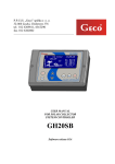
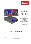
MANUAL FOR CONTROLLER GH10MA CONTROLLER FOR CLUM AND COAL CENTRAL HEATING BOILERS WITH AIR BLOW Program version: 01 USER MANUAL We request that users carefully study applicable Instructions before connecting and starting up any of our products. Should any doubts arise, please contact our Company between 8 a.m. and 4 p.m. Issue I APRIL 2013 GH10MA USER MANUAL PAGE 2 TABLE OF CONTENTS 1. INTRODUCTION ............................................................................................................................ 3 1.1. GRAPHIC SYMBOLS ................................................................................................................................ 3 1.2. KEYBOARD AND FUNCTION KEYS ............................................................................................................. 3 2. GENERAL FEATURES ...................................................................................................................... 4 3. TECHNICAL DATA .......................................................................................................................... 5 4. ELECTRICAL SYSTEM AND CONNECTION RULES .............................................................................. 5 5. QUICK START ................................................................................................................................ 6 6. THE GH10MA OPERATION ............................................................................................................ 7 7. 8. 6.1. OPERATED HEATING SYSTEM .................................................................................................................. 7 6.2. AUTOMATIC OPERATION MODE. .............................................................................................................. 8 6.3. MANUAL OPERATION MODE .................................................................................................................. 9 6.4. VIEWING TEMPERATURES....................................................................................................................... 9 6.5. ALARM CONDITIONS ...........................................................................................................................10 6.6. POWER FAILURE. ................................................................................................................................10 6.7. BOILER BURNOUT DETECTION ...............................................................................................................10 USER SETTINGS ........................................................................................................................... 11 7.1. BOILER TEMPERATURE SETTING (U0) .....................................................................................................11 7.2. HUW/ RETURN TEMPERATURE SETTING (U2) ........................................................................................11 7.3. ANTI-LEGIONELLA FUNCTION (U3) ........................................................................................................11 OPERATING THE HUW BOILER ..................................................................................................... 12 8.1. INSTALATION AND CONNECTIONS ..........................................................................................................12 8.2. CONFIGURATION OF ADDITIONAL PUMP .................................................................................................13 8.3. HUW PRIORITY ..................................................................................................................................13 8.4. SUMMER MODE .................................................................................................................................13 9. TEMPERATURE LIMITER (STB) ...................................................................................................... 14 10. CONNECTION DEVICES TO THE GH10MA CONTROLLER ................................................................. 15 11. INFORMATION ON LABELLING AND COLLECTION OF WORN OUT ELECTRICAL AND ELECTRONIC EQUIPMENT................................................................................................................................ 16 Issue I APRIL 2013 GH10MA USER MANUAL 1. PAGE 3 INTRODUCTION 1.1. Graphic symbols Symbols intended to indicate and at the same time emphasise the importance of text containing information that warns against dangerous situation have the following graphic forms: Warning This symbol is used when it is necessary in described instructions to follow the sequence of carried out operations. The unit may be damaged or destroyed in case of any error or proceeding in discord with the description. Important! This symbol indicates information of particular importance. Reference This symbol indicates occurrence of additional information in a chapter. 1.2. Keyboard and Function Keys PROGRAMMING FIRING UP ON/OFF CH AND HUW PUMPS MANUAL SWITCHING / PUMPS OPERATION INDICATORS Issue I HUW PUMP MANUAL SWITCHING / DOWNWARD VALUE CHANGE CH PUMP MANUAL SWITCHING / UPWARD VALUE CHANGE APRIL 2013 GH10MA USER MANUAL 2. PAGE 4 GENERAL FEATURES The GH10MA Controller is a microprocessor-based device manufactured using the Surface Mount Technology (SMT). It is designed to control the processes of Hot Utility Water (HUW) heating and the main Central Heating (CH) water circuit. Control parameters can be adjusted to the current operating conditions and boiler type. The Controller includes a system protecting from power outages and other different disturbances. The GH10MA Controller is fitted with: inputs: 1. boiler output water temperature measurement (NTC sensor), 2. HUW boiler water /return water temperature measurement (NTC sensor), 3. Flue gas temperature sensor in chimney (PT1000 sensor), It also contains four outputs allowing direct connection of 230 V AC devices, i.e.: fan, CH circulation pump, HUW pump or mixing pump, depending on the type of the controlled heating system. ALWAYS DISCONNECT THE CONTROLLER FROM POWER DURING THUNDERSTORMS Issue I APRIL 2013 GH10MA USER MANUAL 3. PAGE 5 TECHNICAL DATA Power supply 230V AC +10% -15% Operating temperature +5°C to +40°C range Humidity 20% to 80% RH Fan protection Sensors type Sensors operating temperature range 2A NTC 2,2kΩ, PT1000 NTC: 0°C÷100°C PT1000: 0°C÷400°C Output HUW pump / mix pump CH pump Fan* Maximum continuous load 1A 200W 1A 200W 1A 200W PT1000 sensor resistance characteristics NTC sensor resistance characteristics Temp. °C Resistance Ω Temp. °C Resistance Ω 0 7174,89 0 1000,00 10 20 4374,83 2747,10 50 100 1194,00 1385,10 30 1774,91 150 1573,30 40 1172,09 200 1758,60 50 60 70 80 90 100 795,08 547,95 384,62 275,86 202,37 149,16 250 300 350 400 450 500 550 600 1941,00 2120,50 2297,20 2470,90 2641,80 2809,80 2974,90 3137,10 *When a contactor or relay proxy is connected, use a dedicated blowout system (eg varistor). Omission of this security measure may result in malfunction or damage to the controller output. 4. ELECTRICAL SYSTEM AND CONNECTION RULES 1. The boiler room should be equipped with a 230V/50Hz electrical system, according to the applicable regulations. 2. The electrical system (regardless of its type) should be terminated with a connection outlet fitted with a protective terminal. Use of an outlet without a protective terminal causes electrical shock hazard!!! 3. Connect the Controller to a separately installed power line protected with a properly selected quick circuit-breaker or a residual-current device (RCD breaker). Do not connect any other devices to this line!!! THE CONTROLLER IS POWERED FROM 230V/50HZ MAINS ANY REPAIRS MAY BE CARRIED OUT ONLY WITH POWER SUPPLY CUT OFF AT THE FUSE Issue I APRIL 2013 GH10MA USER MANUAL 5. PAGE 6 QUICK START To quickly start the GH10MA Controller, perform the following actions: 1. Connect the device to the 230V AC power system (put the plug in the power outlet). 2. Turn the Controller ON by pressing 3. Press . Screen appears: . Screen appears: and the Controller starts automatic operation according to the factory settings. Table 1 Factory settings chart User parameter Issue I Description Factory setting U0 Boiler preset temperature 600C U2 HUW/return set temperature 400C U3 Anti-Legionella function Yes APRIL 2013 GH10MA USER MANUAL 6. PAGE 7 THE GH10MA OPERATION 6.1. Operated Heating System 6.1.1. Central Heating cycle + HUW cycle INPUTS OUTPUTS T1 – Boiler temp. P1 – HUW pump T2 – HUW temp. P2 – CH pump T3 – Flue gas temp. P3 – Fan INPUTS OUTPUTS T1 – Boiler temp. P1 – Mixing pump T2 – Return temp. P2 – CH pump T3 – Flue gas temp. P3 – Fan 6.1.2. Central Heating cycle + mixing pump Issue I APRIL 2013 GH10MA USER MANUAL PAGE 8 6.2. Automatic operation mode. By pressing , you can turn on the automatic operation mode – (the inflame function is starting) 6.2.1. Firing up Firing up is the first stage of automatic operation, and it is indicated by the blinking of the upper indicator on . FIRING UP process will be completed as soon as the temperature of outlet water from the boiler reaches the value of U0-F29°C. Firing up completion is indicated by lighting of the upper indicator on Automatic mode. During firing up completion fan isn’t working. , all time during When firing up stage exceeds time preset in service parameter F45, and outlet boiler temperature didn’t reach value F6-4°C in this time. Firing up process will be stopped and ALARM 14 will be activated. When it is necessary to burn fuel other than standard, remove the flue exhaust temperature sensor to avoid risk of damaging the sensor 6.2.2. Fan During FIRING UP mode, the fan starts from the minimum speed (run 1) and increases the speed according to the F31 setting, until the maximum speed set in service parameter F2 is reached. The fan operates continuously until the temperature of the water leaving the boiler reaches U0-F29, condition (Tz <U0-F29). After reaching this value, the fan stops and does not operate for approximately 120 seconds. When the controller is connected to the flue sensor and its operation is enabled (F11> 0), then the temperature exceeds 350 ° C the fan speed is limited. The limitation decreases the speed of the fan in proportion to its actual speed, until the fan stops completely. When the firing up mode is complete, the controller switches to automatic mode fan speed regulation. When firing up was successful and the temperature Tco has not reached that set at U0, the fan speed depends on the actual boiler temperature and rate at which the temperature rises, within the time specified in parameter F30. When the boiler set temperature is reached, the fan goes into periodic blow operation or into minimum temperature stabilisation state, characterised by continuous operation at reduced speed. The occurrence and the duration of the algorithm is dependent on the current exhaust and outgoing water temperatures . The service parameter governing the duration of the fan blow is F27. The controller determines intervals between blows using multiples of this parameter. Work and operation of the fan is indicated on the controller display, by the lower horizontal line in front of the temperature measurements. Issue I APRIL 2013 GH10MA USER MANUAL PAGE 9 6.2.3. CH Pump In the AUTO mode, the CH pump starts when the temperature of the boiler water is higher or equal to the value set in the F06 service setting (factory setting is 40°C). Turning the CH pump on and its operation is indicated by lighting the upper indicator on . The Controller turns off the pump when the water temperature drops to the activation temperature minus 4°C. (If the CH pump start temperature is 40°C, then the CH pump stop temperature is 36°C). 6.3. Manual Operation Mode Disable the controller and then switch it back on using the button goes to manual mode. In this mode the user can start and stop the CH and DHW pumps independently of each other. To do this, follow the scheme below: STEP 1 STEP 2 → Controller indicates water temperature measured on the boiler. and HUW pump and CH pump Lower key indicator lights up. Press the key again to deactivate the pump and the indicator. Upper key indicator lights up. Press the key again to deactivate the pump and the indicator. HUW PUMP CAN BE TURNED ON ONLY IF IT IS SELECTED IN SERVICE PARAMETERS 6.4. Viewing Temperatures After pressing , the display shows water temperature at the boiler outlet. Viewing temperatures: flue gas and HUW/return is available in the AUTO and MANUAL modes, but only if the flue gas sensor or HUW/return sensor are properly enabled. Press to view the flue gas temperature. Press the key again to cancel the view. The view is also cancelled after 10s from pressing of the key. Press to get a HUW/return temperature view. Press the key again to cancel the view. The view is also cancelled after 10s from pressing of the key. Issue I APRIL 2013 GH10MA USER MANUAL PAGE 10 6.5. Alarm Conditions The Controller uses 6 different alarm conditions. In each alarm condition, the Controller displays the alarm number and activates the alarm sound output. In case of several alarm conditions occurring simultaneously, their numbers are displayed in sequence. You can exit an alarm condition only by pressing . This does not include the AL12 and AL7 alarm condition. The damage of flue gas temperature sensor (AL7) will not cause enter into a state of alarm, the controller will work as in optimal flue gas temperature conditions. AL7 alarm signalling occurs only when viewing flue gas temperature ( section 6.4). No sound signaling AL7. Alarm conditions: AL1 STB activated or fuse blown AL2 Boiler water outlet temperature sensor failure AL4 HUW/return temperature sensor failure AL7 Flue gas temperature sensor failure AL12 Boiler overheating AL13 Boiler burnout AL14 Flame malfunction (flame extinguished) 6.6. Power Failure. After a power failure the Controller starts to reactivate according to the condition it was in before the power down. The Controller waits 1 minute to stabilise the mains power parameters, and then restores operation with the previously programmed settings. During the waiting period, the display shows time in seconds remaining until the end of the period, along with indication of its condition before the power outage: blinking “A” for AUTO mode, blinking “P” for MAINTAIN mode, blinking “r” for MANUAL mode. 6.7. Boiler Burnout Detection 6.7.1. No Fuel If during automatic operation the boiler outlet water temperature remains below the F08 setting for a period of time set in the F09 setting, then the Controller considers the boiler as “burned out” and enters the AL13 alarm condition. If during automatic mode for time set in F9 parameter the flue gas temperature will be below value set in F11 parameter, the controller recognizes that boiler has expired and AL13 occurs. When F11=0, this detection including flue gas temperature is disabled. Issue I APRIL 2013 GH10MA USER MANUAL 7. PAGE 11 USER SETTINGS 7.1. Boiler Temperature Setting (U0) You can change the boiler temperature setting using the following procedure: STEP 1 STEP 2 → Green LED lights on the key. Display shows current temperature setting. or STEP 3 → Set a new desired temperature within range permitted by the boiler manufacturer. Save the new temperature setting. Move to the U1 setting If during setting the new temperature none of the following keys , , is pressed for 15 s, the new temperature will not be saved and the Controller will exit the programming mode. 7.2. HUW/ Return Temperature Setting (U2) This setting is available to the user only if the HUW heating option or return temperature stabilisation are used, and the user configured the pump with the F00 service parameter by setting it to the values “01”, “02”, “03”, “04” ( section 8.2 page 13). You can modify this setting in a similar way to the described in sections 7.1 and Błąd! Nie można odnaleźć źródła odwołania.. Settings are within the range of 35°C to 65°C. 7.3. Anti-Legionella Function (U3) The GH10MA controller is equipment in Anti-Legionella function which limit growth Legionella pneumophilia bacterium on HUW installation. This function is available for users when value F00 service parameter was adjust on „02”, „03” or „04”. The Legionella bacterium growth in water environment and the best condition is on 38–420C temperature. The Legionella bacterium can cause variety pneumonia disease, called Legion fever. To activate the ANTI-LEGIONELLA function, set the U3 setting to 1. When the function is active, a blinking letter “L” is visible on the left part of the display, before the displayed temperature value. You can turn off the function by modifying the U3 setting to 0, or by pressing function is also cancelled after a power down. Issue I . The anti-legionella APRIL 2013 GH10MA USER MANUAL PAGE 12 The ANTI-LEGIONELLA function has higher priority over other functions, therefore it is performed by the Controller in the first order (superior function). When the function is activated, the temperature of water in the boiler is increased to 70°C and maintained for a period of 10 minutes. TURNING ON OF THE ANTY-LEGIONELLA FUNCTION CAUSES RISE OF THE TEMPERATURE OF HUW WATER UP TO 700C. EXTRA CAUSION WHEN USING HUW. MAY RESULT IN BURNING !!! 8. OPERATING THE HUW BOILER The GH10MA Controller allows connection of an additional pump to control the Hot Utility Water (HUW) in the boiler. 8.1. Instalation and Connections To use the Hot Utility Water (HUW) heating option, perform the following actions: 1. 2. connect the boiler according to the enclosed diagram ( section 6.1.1 page 7). install the HUW temperature sensor in the HUW storage We recommend mounting HUW temperature sensor in GECO measuring drain. You can not mount temperature sensors in measuring drain with water or oil !!! 3. connect the HUW temperature sensor to the Controller at the appropriate terminals as shown in Fig. 2 4. configure the HUW pump for operation ( section 8.2 page 13). HUW temperature sensor is additional equipment and it’s not includes to the standard set controller GH10MA. Additional equipment can be delivery according with additional order. Issue I APRIL 2013 GH10MA USER MANUAL PAGE 13 8.2. Configuration of Additional Pump This procedure allows you to connect an additional pump that can be used as a mixing pump or a Hot Utility Water (HUW) pump operating with or without higher priority. The HUW pump is started when the boiler outlet water temperature is higher than 40°C and higher than the water in the HUW boiler (to prevent cooling of the HUW boiler), and the HUW boiler temperature is lower than the temperature set in the U2 setting ( section 0 page 11). Pump operation is indicated by a dot on the display next to the fan symbol. If the boiler room is configured as shown in the diagram ( section 6.1.1 page 7) then the boiler controller has no external alarm output, but allows to view the HUW boiler temperature by pressing . Use the following procedure to program operation of an additional pump in the Controller: STEP 1 STEP 2 → Display shows „─ ─ ─ ─” STEP 3 → Press and hold for 2s or Set the desired F00 value 00 – no pump operation 01 – mixing pump 02 – HUW pump winter mode without priority 03 – HUW pump winter mode with priority 04 – HUW pump summer mode STEP 4 → Save the new setting 8.3. HUW Priority The GH10MA Controller allows to set operation of the HUW pump with priority. If you choose this mode of HUW pump operation, the hot utility water heating is a higher priority function in the Controller. To do this, set the F00 service setting to the value of “3”. 8.4. Summer Mode The GH10MA Controller is equipped with a SUMMER MODE option that allows you to turn off the CH pump for the summer season, and the boiler operates only to supply the HUW water. To do this, set the F00 service setting to the value of “4”. Issue I APRIL 2013 GH10MA USER MANUAL 9. PAGE 14 TEMPERATURE LIMITER (STB) The GH10MA Controller can be equipped with an additional independent temperature limiter STB via terminals 15 and 16. WHEN THE TEMPERATURE LIMITER IS NOT USED, TERMINALS 15 AND 16 SHOULD BE SHORTED. If due to boiler temperature rise the temperature limiter is activated and opens its terminals, it will disable feeder and fan power supply in order to stop fuel and air delivery do the boiler. After approximately 5s from limiter activation the Controller indicates the AL1 alarm. Return to normal boiler operation is possible when the boiler temperature drops to a level enabling limiter reset (temperature level depends on the limiter model used). For safety reasons the Controller does not resume automatic operation on its own. For the Controller to resume operation you have to, after resetting the limiter, press – pressing for the first time cancels the alarm and disables the Controller, – pressing for the second time reactivates the Controller, – pressing twice: causes the Controller to switch to automatic operation mode. CAPILLARY TUBE PUNCTURE OR BREAKAGE INDICATES THAT TEMPERATURE LIMITER FILLED WITH LIQUID LEAKS, WHICH RESULTS IN ABNORMAL OPERATION OF THE GH10MA CONTROLLER. IN CASE IF THE ABOVE-MENTIONED DEFECT IS FOUND, IT WILL BE NECESSARY TO DISCONNECT TEMPERATURE LIMITER FROM THE GH10MA CONTROLLER, REMOVE IT AND REPLACE WITH A NEW DEVICE. Issue I APRIL 2013 GH10MA USER MANUAL PAGE 15 10. CONNECTION DEVICES TO THE GH10MA CONTROLLER OUTPUTS INPUTS 14 L — Fan 50, 51 — Out water temperature sensor 12 N — Fan 52, 53 — H.U.W /Return temp. sensor 11 L — --- 54, 55 — Flue gas temperature sensor 09 N — --- 06 L — Central Heating Pump C.H. 05 N — Central Heating Pump C.H. 08 L — H.U.W. Pump/ Mixing Pump 07 N — H.U.W. Pump/ Mixing Pump 02 N — Power Supply 230V 01 L — Power Supply 230V Fig. 1 Diagram of connection outputs and inputs devices and temperature sensor in the GH10MA controller. ANY ADDITIONAL EQUIPMENT MAY BE CONNECTED TO THE GH10MA CONTROLLER ONLY BY PERSON LICENSED TO PERFORM ELECTRICAL INSTALLATION WORKS. Issue I APRIL 2013 GH10MA USER MANUAL PAGE 16 11. INFORMATION ON LABELLING AND COLLECTION OF WORN OUT ELECTRICAL AND ELECTRONIC EQUIPMENT CAUTION! This symbol placed on the product or its packaging indicates the need for selective collection of worn out electrical and electronic equipment. It means that this product should not be disposed of with other household wastes. Proper disposal of aged and worn out electrical and electronic equipment will help to avoid potentially adverse effects for environment and human health. It is the user’s responsibility to collect worn out equipment separately, and to return it to an authorized disposal company. Issue I APRIL 2013 GH10MA USER MANUAL PAGE 17 P.P.U.H. „Geco” Sp. z o.o. Cholerzyn 376, 32-060 Liszki, Poland ph. 012/636-98-11, 636-12-90 fax. 012/636-20-02 http://www.geco.pl e-mail: [email protected] Issue I APRIL 2013