1
Compiler Reference Manual
by
John Diener and Andy Klumpp
ASH WARE, Inc.
Version 2.40
11/1/2015
(C) 2007-2015
page 2, Compiler Reference Manual
Compiler Reference Manual
Table of Contents
Foreword
9
Part 1 Introduction
11
Part 2 Supported Targets
13
Part 3 References
15
Part 4 Keywords and Abbreviations
17
Part 5 eTPU Programming Model
19
5.1 eTPU
..............................................................................................................
Types
19
5.2 Pointers
.............................................................................................................. 22
5.3 eTPU
..............................................................................................................
Data Packing
22
Global
.....................................................................................................................................
Variables
23
Static
.....................................................................................................................................
Variables in Callable C-Functions
24
eTPU2
.....................................................................................................................................
Engine Relative Address Space
25
eTPU
.....................................................................................................................................
Channel Fram e Variables
25
Channel
.....................................................................................................................................
Fram e PACKTIGHT Mode
26
Local/Stack
.....................................................................................................................................
Variables
27
Structures
.....................................................................................................................................
& Unions
27
Structure
.....................................................................................................................................
PACKTIGHT Mode
28
Structure
.....................................................................................................................................
Bit Fields
29
Arrays
..................................................................................................................................... 30
Array
.....................................................................................................................................
PACKTIGHT Mode
30
ANSI
.....................................................................................................................................
Mode
31
5.4 eTPU
..............................................................................................................
Hardware Access
32
Channel
.....................................................................................................................................
Hardw are Access
32
Baseline
.....................................................................................................................................
eTPU Channel Hardw are Program m ing Model
32
eTPU+
.....................................................................................................................................
Extensions to the Channel Hardw are Program m ing Model
33
eTPU2
.....................................................................................................................................
Extensions to the Channel Hardw are Program m ing Model
35
Register
.....................................................................................................................................
Access
36
ALU
.....................................................................................................................................
Condition Code Access
38
Built-in
.....................................................................................................................................
/ Intrinsic Functions
39
Compiler Reference Manual, page 3
Compiler Reference Manual
Compatibility
.........................................................................................................................
Functions
39
ETEC
.........................................................................................................................
Coherency & Synchronization Control
40
TR18037
.........................................................................................................................
Fixed-point Library Support
40
ALU/MDU
.........................................................................................................................
Intrinsics
41
.............................................................................................................
Rotate
Right Support
41
.............................................................................................................
Absolute
Value Support
42
.............................................................................................................
Shift
Register Support
42
.............................................................................................................
Shift
By 2(N+1) Support
42
.............................................................................................................
Set/Clear
Bit Support
43
.............................................................................................................
Exchange
Bit Support
43
.............................................................................................................
MAC/MDU
Support
44
5.5 ETEC
..............................................................................................................
eTPU Class
45
Extension
.....................................................................................................................................
Syntax Details
48
Native
.....................................................................................................................................
ETEC Form at
50
Com
.....................................................................................................................................
patibility Mode
52
5.6 Code
..............................................................................................................
Fragments
55
_eTPU_thread
.....................................................................................................................................
Calls
57
5.7 State
..............................................................................................................
Switch Constructs
57
State
.....................................................................................................................................
Enum eration
57
State
.....................................................................................................................................
Variable
58
State
.....................................................................................................................................
Sw itch
59
Additional
.....................................................................................................................................
Notes
63
5.8 eTPU
..............................................................................................................
Constant Tables
63
5.9 ETEC
..............................................................................................................
Local Variable Model & Calling Conventions
65
Stack-based
.....................................................................................................................................
Model
65
Calling
.....................................................................................................................................
Convention
68
Scratchpad-based
.....................................................................................................................................
Model
70
Calling
.....................................................................................................................................
Convention
72
5.10 In-Line
..............................................................................................................
Assembly
74
Calling
.....................................................................................................................................
the Error Handler from User Code
75
5.11 ETEC
..............................................................................................................
Standard Header Files
75
Part 6 C Preprocessing
77
Part 7 Auto Header Generation
79
7.1 Auto-Struct
..............................................................................................................
File
79
24-bit
.....................................................................................................................................
vs. Non-24-bit Accesses
80
Nam
.....................................................................................................................................
ing Conventions
81
eTPU
.....................................................................................................................................
Data in Auto-Structs
82
eTPU
.....................................................................................................................................
Structures/Unions
83
page 4, Compiler Reference Manual
Compiler Reference Manual
Arrays
.....................................................................................................................................
in Auto-Structs
84
Bit-field
.....................................................................................................................................
and _Bool Variables
87
Exam
.....................................................................................................................................
ple Code
88
7.2 Auto-Defines
..............................................................................................................
File
89
Global
.....................................................................................................................................
Prepended Mnem onic
89
Auto
.....................................................................................................................................
Header File Nam e
89
Text
.....................................................................................................................................
Generation
89
Type
.....................................................................................................................................
Inform ation
90
Array
.....................................................................................................................................
Variables
91
_Bool
.....................................................................................................................................
Type Variables
91
Struct/Union
.....................................................................................................................................
Variables
91
Tag
.....................................................................................................................................
Types (Structures, Unions, Enum erations)
92
Global
.....................................................................................................................................
Mnem onic
94
Settings,
.....................................................................................................................................
Register Fields, and Mnem onic
94
Include
.....................................................................................................................................
Race Keepout
101
Freescale
.....................................................................................................................................
API com patibility
101
ASH
.....................................................................................................................................
WARE Sim ulator Com patibility
101
Support
.....................................................................................................................................
for Additional Languages
101
SCM
.....................................................................................................................................
ARRAY
101
PWM
.....................................................................................................................................
Exam ple
102
Part 8 Initialized Data Files
103
8.1 Initialized
..............................................................................................................
Global Memory
103
8.2 Initialized
..............................................................................................................
Channel Memory
104
8.3 Using
..............................................................................................................
the Initialized Data Macros in the Simulator
105
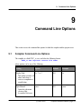
Part 9 Command Line Options
107
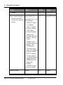
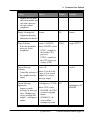
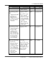
9.1 Compiler
..............................................................................................................
Command Line Options
107
9.2 C..............................................................................................................
Preprocessor Command Line Options
117
9.3 Console
..............................................................................................................
Message Verbosity (-Verb)
122
9.4 Version
..............................................................................................................
(-Version)
123
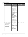
Part 10 Limitations
125
10.1 Restrictions
..............................................................................................................
to the ISO/IEC 9899 C Definition
125
Part 11 Supported Features
127
11.1 General
..............................................................................................................
C Language Support
127
Compiler Reference Manual, page 5
Compiler Reference Manual
11.2 eTPU
..............................................................................................................
Programming Model Support
127
11.3 Compatibility
..............................................................................................................
Mode Support
128
Entry
.....................................................................................................................................
Table Support
128
#pragm
.....................................................................................................................................
a support
128
Part 12 Appendix A : Pragma Support
129
12.1 Verify
..............................................................................................................
Version
130
12.2 Disabling
..............................................................................................................
Optimization in Chunks of Code
131
12.3 Disabling
..............................................................................................................
Optimizations by Type
131
12.4 Atomicity
..............................................................................................................
Control
132
12.5 Optimization
..............................................................................................................
Boundary (Synchronization) Control
132
12.6 Thread
..............................................................................................................
Length Verification (WCTL)
132
12.7 Forcing
..............................................................................................................
the WCTL
134
12.8 Excluding
..............................................................................................................
a thread from WCTL
134
12.9 Loop
..............................................................................................................
Iteration Count
134
12.10 Code
..............................................................................................................
Size Verification
135
12.11 Memory
..............................................................................................................
Size (Usage) Verification
135
12.12 Same
..............................................................................................................
Channel Frame Base Address
136
12.13 Auto-defines
..............................................................................................................
Export
136
12.14 Private
..............................................................................................................
Channel Frame Variables
138
Part 13 Appendix B : Data Packing
Details
139
13.1 Channel
..............................................................................................................
Frame FASTACCESS Mode
139
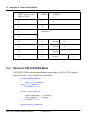
13.2 Structure
..............................................................................................................
FASTACCESS Mode
140
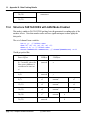
13.3 Structure
..............................................................................................................
PACKTIGHT with ANSI Mode Enabled
141
13.4 Structure
..............................................................................................................
FASTACCESS with ANSI Mode Enabled
142
13.5 Array
..............................................................................................................
FASTACCESS Mode
143
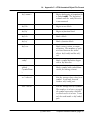
Part 14 Appendix C : eTPU Annotated
Object File Format
145
14.1 Code
..............................................................................................................
Labels
152
page 6, Compiler Reference Manual
Compiler Reference Manual
14.2 Entries
.............................................................................................................. 153
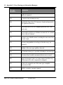
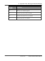
Part 15 Appendix D : Error, Warning and
Information Messages
155
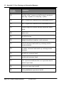
15.1 Compiler
..............................................................................................................
Error Messages
155
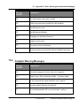
15.2 Compiler
..............................................................................................................
Warning Messages
157
Compiler Reference Manual, page 7
page 8, Compiler Reference Manual
Compiler Reference Manual
Compiler Reference Manual, page 9
page 10, Compiler Reference Manual
1. Introduction
1
Introduction
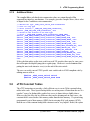
The eTPU Embedded C Compiler System is based upon the ISO/IEC 9899 C standard
(“C99”) and the ISO/IEC TR 18037 Embedded C extension. ETEC is a highly optimizing
C compiler for all versions of the eTPU. ETEC has its own version of the programming
model with regards to entry table definition and thread function definition, but also has a
compatibility mode for compiling software written using existing programming paradigms.
This document covers the details of these programming models, the ETEC Tools Suite
itself such as command line options, as well as details on the various outputs of the ETEC
Compiler Tools Suite.
(C) 2007-2015
Compiler Reference Manual, page 11
page 12, Compiler Reference Manual
2. Supported Targets
2
Supported Targets
The ETEC C compiler toolkit current supports the following targets.
eTPU - select Qorivva MPC55xx parts, select Coldfire MCF52xx parts (compiler/linker
option '-target=etpu1')
eTPU2 - select Qorivva MPC56xx parts, select STMicro SPC563Mxx parts (compiler/
linker option '-target=etpu2')
eTPU2+ - select Qorivva MPC57xx parts. There is not a separate target option for
eTPU2+ - use the eTPU2 target. The eTPU2+ has no instruction set differences versus
the eTPU2. The only programming model difference is that a third bit has been added to
the missing tooth count field in the tooth program register (TPR). If using the default TPR
struct defined in the ETpu_Hw.h header file, this third bit is accessed via the previously
unused TPR10 field.
(C) 2007-2015
Compiler Reference Manual, page 13
page 14, Compiler Reference Manual
3. References
3
References
ISO/IEC 9899:TC2 Programming Languages – C
ISO/IEC TR 18037 Programming Languages – C – Extensions to support embedded
processors
Enhanced Time Processing Unit (eTPU) Preliminary Reference Manual (ETPURM/D
5/2004 Rev 1)
(C) 2007-2015
Compiler Reference Manual, page 15
page 16, Compiler Reference Manual
4. Keywords and Abbreviations
4
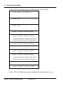
Keywords and Abbreviations
Channel Frame
The collection of channel variables associated with a
single eTPU Function or ETEC eTPU Class.
Channel
Variable
A variable that is addressed relative to the channel
base register. This storage is static and there is one
copy per channel to which it is assigned at run-time.
Sometimes channel variables are referred to as
parameters.
ETEC
eTPU Embedded C Compiler
eTPU
Enhanced Time Processor Unit (and derivatives)
eTPU-C
The C code development system for the eTPU by Byte
Craft Limited.
eTPU Class
The native ETEC programming model aggregates all
threads, methods (C functions), channel variables and
entry tables associated with a single application into a
class-like structure called an eTPU class.
eTPU Function
An eTPU-C term that refers to a C function that defines
(C) 2007-2015
Compiler Reference Manual, page 17
4. Keywords and Abbreviations
a set of channel variables, an entry table, and the
threads that make up the vectors for that entry table.
With regards to ETEC, it refers to entry tables, channel
variables and threads that are all associated, an ETEC
“class”.
eTPU Thread
An ETEC term. A C function that can be used as an
entry vector, but cannot be called from any other C
code.
SCM
Shared Code Memory. The location of the eTPU code
and entry tables. Not readable from the eTPU.
SDM
Shared Data Memory. Multi-ported data memory
accessible from the host CPU and the eTPU.
Historically this memory has been referred to as
parameter RAM.
page 18, Compiler Reference Manual
(C) 2007-2015
5. eTPU Programming Model
5
eTPU Programming Model
This section discusses the two major portions of the eTPU hardware programming model –
direct access to the eTPU hardware, and the syntax for defining entry tables. Unlike a
more conventional microprocessor, the eTPU does not typically process in any kind of
continuous manner. Rather, it behaves more like a set of interrupt handlers reacting to
events. Entry tables map events to the code / threads that need to process the event. In
between such activations the eTPU microengine is completely idle.
ETEC uses a stack-based approach for local variables and function calls. The user must
allocate stack space in SDM. This portion of the programming model is discussed in more
detail in the section 4.7.
5.1
eTPU Types
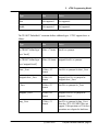
The C basic types map to the eTPU hardware as follows:
Type
Size
Notes
char, unsigned char
8 bits
int8 is a synonym for char
short, unsigned short
16 bits
int16 is a synonym for short
(C) 2007-2015
Compiler Reference Manual, page 19
5. eTPU Programming Model
Type
Size
Notes
int, unsigned int
24 bits
int24 is a synonym for int
long int, unsigned long int
32 bits
int32 is a synonym for long int; 32-bit
int usage is limited as the eTPU ALU
only operates on 24-bits. Essentially
only load/store operations are
supported. Any use of 32-bit data in an
expression that involves arithmetic
operations outside assignment (load/
store) result in compilation errors.
Conversion via typecast to signed/
unsigned int32 is supported.
long long int, unsigned long 32 bits
long int
treated like long types (see comment
above)
_Bool
_Bool needs to hold 0 or 1. By default,
it is packed into 1 bit that is part of an
8-bit unit. Global _Bool variables
consume an entire 8-bit unit by
themselves so that external linking
works correctly. Up to 8 channel
frame _Bool variables can packed into
one 8-bit unit.
1 bit / 8 bits
Arrays of _Bool are treated as special
“bit arrays” and are limited to a length
of 24.
If the –ansi mode is specified, then all
_Bools consume and 8 bits and arrays
of _Bools are similar to arrays of
chars.
_Complex
page 20, Compiler Reference Manual
Not supported
Not supported
(C) 2007-2015
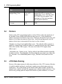
5. eTPU Programming Model
Type
Size
Notes
float
Not supported
Not supported
double
Not supported
Not supported
The TR 18037 Embedded C extensions defines additional types. ETEC supports these as
follows:
Type
Size
Notes
no TR18037 defined type
8 bits, s.7 format
fract8 is a synonym
8 bits, 0.8 format
unsigned fract8 is a synonym
short _Fract
16 bits, s.15
format
fract16 is a synonym for short _Fract
unsigned short _Fract
16 bits, 0.16
format
unsigned fract16 is a synonym for
unsigned short _Fract
_Fract
24 bits, s.23
format
fract24 is a synonym for _Fract
unsigned _Fract
24 bits, 0.24
format
unsigned fract24 is a synonym for
unsigned _Fract
long _Fract
32 bits, s.31
format
fract32 is a synonym for long _Fract.
Note the eTPU ALU/MDU does not
support 32-bit operations so 32-bit fract
operations are relegated to load/store.
[use 'fract8']
no TR18037 defined type
[use 'unsigned fract8']
(C) 2007-2015
Compiler Reference Manual, page 21
5. eTPU Programming Model
5.2
Type
Size
Notes
unsigned long _Fract
32 bits, 0.32
format
unsigned fract32 is a synonym for
unsigned long _Fract. Note the eTPU
ALU/MDU does not support 32-bit
operations so 32-bit fract operations
are relegated to load/store.
_Accum
TBD
TBD
Pointers
Pointers in the eTPU programming model are sized to 24-bits as this is the natural size of
the machine (16-bits would provide sufficient range, however). In the default mode,
pointers to 8-bit types increment in 1-byte steps, 16-bit types increment in 2-byte steps, and
pointers to 24-bit types increment in 4 bytes steps. Some data packing modes cause all
pointers to basic types to increment in 4 byte steps (see later sections).
All pointers are always kept in global address space. Thus when the address operator is
applied to a channel frame variable the address is computed to be the sum of the channel
frame offset and the CPBA register. The same is true with eTPU2 engine-relative
address space.
_Bool pointer note. Pointers to type _Bool are allowed, and will increment/decrement like
a pointer to an 8-bit. Depending upon _Bool bit packing they may point to any of the 8 bits
in a _Bool unit. It is recommended pointers to type _Bool not be used, unless in ANSI
mode.
5.3
eTPU Data Packing
Because of the unique memory & addressing architecture of the eTPU, memory allocation
of variables and data packing is a much more complex process than in many processor
architectures. The sections below provide details on how global variables are allocated,
channel frame variables, and lastly the aggregate types: structures/unions and arrays. Note
that the array packing option also impacts the behavior of pointer arithmetic; see section
page 22, Compiler Reference Manual
(C) 2007-2015
5. eTPU Programming Model
4.3.11 for details.
Most of the packing algorithms are based around the following information:
The natural data sizes of the eTPU memory architecture are 1-byte, 3-byte and 4-byte
(limited 4-byte support, however – just load/store).
Single-byte data is best accessed when placed in a modulo 4 address, unless it does not
share a 3-byte location with any other data.
3-byte data is best accessed when placed in an address that is modulo 4 plus 1.
Packing multiple non-3-byte (< 3) data into 3-byte locations can result in data coherency
issues.
Multiple data packing modes are available in order to help tailor compilation to the
application requirements. Note however, that linking object files compiled under different
modes will result in link errors in many cases. It is highly recommended that all object files
to be linked be compiled with the same data packing settings (the linker has checks for
this).
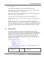
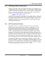
5.3.1
Global Variables
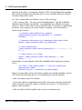
Because global variables can be declared in one translation unit (source file), and
referenced externally by other translation units, the global variable packing algorithm must
properly account for this in order to have a reasonable linking process. To that end, all
global variables are allocated at natural locations for their size. Thus all 1-byte data
variables are located at modulo 4 addresses, all 3 byte variables at modulo 4 plus 1
addresses, etc. Note that by default global variables are located starting at address 0 of
shared data memory (SDM).
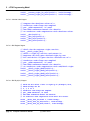
Given these global declarations:
char c1, c2, c3, c4;
int32 s32;
unsigned int16 u16;
int s24;
struct SomeStruct somestruct; // sizeof(SomeStruct) == 8
The memory allocation looks like:
SDM Address
MSByt
(C) 2007-2015
3 LSBytes
Compiler Reference Manual, page 23
5. eTPU Programming Model
e
0
c1
unused
4
c2
s24
8
c3
unused
12
c4
16
s32
20
somestruct
u16
24
Note that the order of declaration does not necessarily match the address order of the
variable locations. This is necessary to avoid significant wasted memory. Also note that
global variables declared in different translation units may be intermixed in the final linked
memory map depending upon sizes and fitting (link) order.
5.3.2
Static Variables in Callable C-Functions
Because these types of C functions are not associated with a particular eTPU Function (or
eTPU Class), any static variables declared within them cannot be assigned to a channel
frame. Thus they are assigned global storage. WARNING: if using a dual eTPU part (e.
g. MPC5554) and running code containing such static variables on BOTH eTPUs, there is
risk of collisions between the two. This must be taken into consideration when using such
a construct; use of semaphore protection may be required depending upon the intended
application.
page 24, Compiler Reference Manual
(C) 2007-2015
5. eTPU Programming Model
5.3.3
eTPU2 Engine Relative Address Space
Variables can specified for allocation in engine-relative address space through use of the
_ENGINE intrinsic address-space type qualifier. Note that automatic variables cannot be
so qualified; variables declared within the scope of a function with the _ENGINE qualifier
must have a storage class of either static or extern. Such variables are allocated with
respect to the user-configured engine base address register.
_ENGINE int24 e_duty_cycle;
On a dual-eTPU2 microcontroller, each engine references unique copies of e_duty_cycle,
assuming the engine-relative base address has been configured properly for each eTPU2.
It is generally recommended that the use of engine-relative variables be avoided as they
complicate the memory layout. An exception is if the user is also selecting the engine
scratchpad programming model.
5.3.4
eTPU Channel Frame Variables
Although channel frames are configured and located at run-time, channel variable
allocation is static to the channel frame base and thus the compilation process. The
mechanism for declaring channel variables differs between compatibility mode and
enhanced ETEC mode, but in either case there are two packing modes for channel
variables. The default mode is called “PACKTIGHT”, and its goal is to use the least
memory possible in the allocation of the channel frame while still providing reasonable
performance. The other mode is called “FASTACCESS”, which places variables at their
most natural locations for efficient processing, even though it can result in more “holes” of
unused memory in a channel frame and thus greater memory usage. In either case, the
order of declaration does not necessarily result in monotonically increasing address offsets.
The default PACKTIGHT mode is described in more detail below; FASTACCESS is
described in an appendix. In either case the algorithm could change slightly over time, OR
the optimizer could re-arrange parameters depending upon level of optimization specified.
Should a user want complete control over the location of channel variables they should use
the explicit locating mechanism described in section 4.3.8 (TBD).
(C) 2007-2015
Compiler Reference Manual, page 25
5. eTPU Programming Model
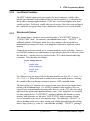
5.3.5
Channel Frame PACKTIGHT Mode
The PACKTIGHT mode packing algorithm first locates every variable of size 3 bytes or
larger. Next variables of size 2 bytes are located, followed by 1-byte variables last.
The set of channel frame variables (likely declared as parameters to an eTPU function in
compatibility mode):
int x, y; // 24-bit vars
char c1, c2, c3, c4, c5, c6;
short a, b, c; // 16-bit vars
struct SomeStruct somestruct; // sizeof(SomeStruct) == 8
Would get packed like:
SDM Channel Frame
Address Offset
MSByte
3 LSBytes
0
c1
x
4
c2
y
8
somestruct
12
16
a
b
20
c
c3
24
c5
c6
c4
unused
Note that tight packing can potentially introduce coherency issues, such as at address
offsets 16 (a, b) and 20 (c3, c4, c). In general, it is best to avoid 16-bit data in eTPU code,
and to avoid 8-bit data ending up in non-optimal locations.
page 26, Compiler Reference Manual
(C) 2007-2015
5. eTPU Programming Model
5.3.6
Local/Stack Variables
The ETEC compiler aggressively uses registers for local / temporary variables when
possible, but sometimes such variables need to be stored in memory (e.g. when they have
the & address operator applied to them). ETEC uses a stack-based approach for local
variable overflow. Each stack variable takes up at least one 4-byte data word, and more if
the variable has size greater than 4 bytes, allowing for efficient access to such variables.
5.3.7
Structures & Unions
Like channel frames, structures can be packed in either a “PACKTIGHT” mode or a
“FASTACCESS” mode. For structures, one additional mode exists – “LEGACY”. An
additional variable is ANSI mode, which forces the compiler to allocate members in
monotonically increasing offset order, even though the result can be significant wasted
memory.
Unions do not need to be packed, per se, as union members overlay each other. However,
by ANSI/ISO standard every union member is expected to be placed at an offset of 0 from
the union base… but that is not very practical on the eTPU with its unusual addressing
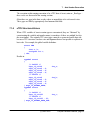
constraints. Take this union for example:
union ExampleUnion
{
int24 s24;
int8 array[4];
int16 s16;
int8 s8;
};
For efficient access, the byte offsets for the union members are best s24 -> 1, array -> 0,
s16 ->2, s8 -> 0. When ANSI mode is enabled, such a union would generate a warning;
the compiler will not (at this time) attempt to generate ANSI-compatible unions.
The data packing of C structures faces some of same issues discussed in channel frame
packing, with an additional twist. Per ANSI/ISO standard, struct member offsets are
expected to be in monotonically increasing order, however, on the eTPU this can result in
impractical data packing and significant memory waste. Once again there are essentially
two data packing flavors: “PACKTIGHT” attempts to minimize the amount of wasted
memory, while structures are laid out in “FASTACCESS” mode to promote efficient
access, potentially at the cost of extra memory usage. The third mode, “LEGACY”, is
only for handling certain cases where existing code is highly dependent upon the packing
done by legacy tools (e.g. a mix of C code and inline assembly). “LEGACY” packing is
(C) 2007-2015
Compiler Reference Manual, page 27
5. eTPU Programming Model
very similar to “PACKTIGHT” except that members such is 8-bit variables will pack in
holes only within the last 4 bytes; they will not get packed back at the very first hole
available in the structure.
The default mode packing algorithm, PACKTIGHT, is detailed below. The algorithm may
change over time so it is recommended to always use the auto define data for referencing
structures from the host side. If complete control of data packing is required, the explicit
member locating constructs should be used. Also note that the ANSI mode affects
structure packing by forcing offsets to monotonically increasing.
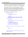
5.3.8
Structure PACKTIGHT Mode
This is the default mode of the compiler, and uses the same algorithm as the channel frame
PACKTIGHT pack mode. The one difference occurs on small structs where the
component member’s size totals 3 bytes or less. In this case the struct is packed to fit in
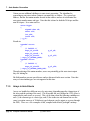
the same slot that basic typed variables of the same size would occupy. Some examples:
struct ByteBitfield
{
int8 a:2;
int8 b:3;
int8 c:3;
}; // sizeof() == 1, gets packed like a char in channel
frame, array, etc.
struct TwoByteStruct
{
char x; // offset 0
char y; // offset 1
}; // sizeof() == 2, gets packed like an int16
struct ThreeByteStruct
{
int16 twobytes; // offset 1
int8 onebyte; // offset 0
}; // sizeof() == 3, gets packed like an int24
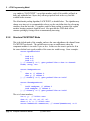
The set of struct members:
int x, y; // 24-bit vars
char c1, c2, c3, c4, c5, c6;
short a, b, c; // 16-bit vars
struct SomeStruct somestruct; // sizeof(SomeStruct) == 8
page 28, Compiler Reference Manual
(C) 2007-2015
5. eTPU Programming Model
Would get packed like:
SDM Channel Frame
Address Offset
MSByt
e
3 LSBytes
0
c1
x
4
c2
y
8
somestruct
12
16
a
b
20
c
c3
24
c5
c6
c4
unused
The sizeof() this struct would be 28, including the two padding bytes at the end.
5.3.9
Structure Bit Fields
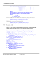
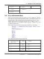
Bitfields can be made out of int8, int16 or int24 types. Bitfields are allocated starting with
least significant bit of the storage unit, and are never split across storage units by ETEC.
struct BitFieldExample
{
int24 x : 10; // bit offset == 14
int24 y : 10; // bit offset == 4
int24 z : 10; // bit offset == 46
}; // sizeof() == 8
Structures (and thus bitfields) can also be mapped onto a register using the TR18037
named register concept, e.g.
struct tpr_struct {
(C) 2007-2015
Compiler Reference Manual, page 29
5. eTPU Programming Model
unsigned int16 TICKS
unsigned int16 TPR10
unsigned int16 HOLD
unsigned int16 IPH
unsigned int16 MISSCNT
unsigned int16 LAST
} register _TPR tpr_reg;
:
:
:
:
:
:
10;
1;
1;
1;
2;
1;
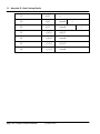
5.3.10 Arrays
The packing of arrays is also tied into how pointer arithmetic is handled in the compilation
process. Pointer arithmetic follows the array stride size settings, which are governed by
the array packing mode. Once again, the modes are termed PACKTIGHT (default) and
FASTACCESS. Because this setting affects pointer arithmetic (e.g. in FASTACCESS
mode incrementing a char pointer results in an increment by 4 bytes), care should be taken
in using the non-default setting. Additional PACKTIGHT mode specifics are given below;
further FASTACCESS information is in the appendix.
Note that FASTACCESS and ANSI modes are incompatible and compilation will error.
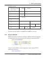
5.3.11 Array PACKTIGHT Mode
In array PACKTIGHT mode, the array stride size matches the element size with the
exception of 24-bit elements. For element types with a byte size of 3, the array stride size
is 4 bytes, thus leaving an unused byte between each element. These unused bytes are
open to be allocated, except if ANSI mode is enabled. Once an element is greater than 4
bytes in size, the stride size is rounded up to the next multiple of 4 bytes. Once again, the
unused memory between array elements is open for allocation (under default settings).
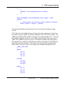
Some example declarations and the ensuing memory allocations are shown below:
char a[6];
int b[3];
struct FiveByteStruct
{
char f1;
int f2;
char f3;
} c[2];
int24 x;
int8 y;
int16 z;
page 30, Compiler Reference Manual
(C) 2007-2015
5. eTPU Programming Model
The resulting memory allocation map would look like (PACKTIGHT channel frame pack
mode):
SDM Channel Frame
Address Offset
MSByt
e
3 LSBytes
0
a[0]
a[1]
a[2]
4
a[4]
a[5]
z
8
y
b[0]
12
unused
b[1]
16
unused
b[2]
20
c[0].f1
c[0].f2
24
c[0].f3
x
28
c[1].f1
c[1].f2
32
c[1].f3
unused
a[3]
5.3.12 ANSI Mode
ANSI mode (controlled with the –ansi option) has been mentioned several times above.
Essentially it forces ANSI/ISO compatibility wherever possible, particularly in data packing
(structs are always packed in order, for example). Also, _Bools are packed as 8-bit units
rather than as single bits (LSB holds the 0 or 1 value). It is not recommended for use in
production eTPU code as it typically increases memory usage and decreases performance.
(C) 2007-2015
Compiler Reference Manual, page 31
5. eTPU Programming Model
5.4
eTPU Hardware Access
Most eTPU hardware access involves the channel hardware or portions of the register set.
The underlying hardware programming model described here is defined in the ETpu_Hw.h
header file that is part of the ETEC distribution.
5.4.1
Channel Hardware Access
The channel hardware is represented by a large structure of bitfields. Each field
represents an accessible piece of channel hardware. This structure type has the name
chan_struct and as part of the standard programming model a “variable” of this type
named “channel” is declared. No actual memory space is allocated. Most fields are
write-only, none are readable in the normal sense. Some are test-only, whereas a few are
both writeable and testable.
5.4.2
Baseline eTPU Channel Hardware Programming Model
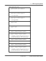
The eTPU chan_struct is defined as:
typedef struct
CIRC
int
ERWA
int
ERWB
int
FLC
int
IPACA int
IPACB int
LSR
int
MRLA
int
MRLB
int
MRLE
int
MTD
int
OPACA int
OPACB int
PDCM
int
PIN
int
TBSA
int
TBSB
int
TDL
int
SMPR
int
{
:
:
:
:
:
:
:
:
:
:
:
:
:
:
:
:
:
:
:
2
1
1
3
3
3
1
1
1
1
2
3
3
4
3
4
4
1
2
;
;
;
;
;
;
;
;
;
;
;
;
;
;
;
;
;
;
;
//
//
//
//
//
//
//
//
//
//
//
//
//
//
//
//
//
//
//
//
page 32, Compiler Reference Manual
write-only
write-only
write-only
write-only
write-only
write-only
writeable, testable, entry condition
writeable, testable
writeable, testable
write-only
write-only
write-only
write-only
write-only
write-only
write-only
write-only
write-only
writeable, testable
[setting to -1 triggers semaphore free]
(C) 2007-2015
5. eTPU Programming Model
FLAG0 int
FLAG1 int
FM0
int
FM1
int
PSS
int
PSTI
int
PSTO
int
TDLA
int
TDLB
int
} chan_struct;
:
:
:
:
:
:
:
:
:
1
1
1
1
1
1
1
1
1
;
;
;
;
;
;
;
;
;
//
//
//
//
//
//
//
//
//
writeable (also via FLC), entry condition
writeable (also via FLC), entry condition
test-only
test-only
test-only
test-only
test-only
test-only
test-only
See eTPU documentation for the details on each field.
Note that the ETpu_Std.h header file defines many macros that simplify interaction with
the channel hardware and make it more user-friendly.
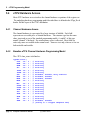
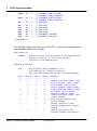
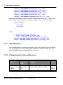
5.4.3
eTPU+ Extensions to the Channel Hardware Programming Model
For the eTPU+, chan_struct has been modified and extended to the following:
typedef struct {
CIRC
int :
ERWA
int :
ERWB
int :
FLC
int :
IPACA
int :
IPACB
int :
LSR
int :
MRLA
int :
MRLB
int :
MRLE
int :
MTD
int :
OPACA
int :
OPACB
int :
PDCM
int :
PIN
int :
TBSA
int :
TBSB
int :
TDL
int :
UDCMRWA int :
SMPR
int :
3
1
1
3
3
3
1
1
1
1
2
3
3
4
3
4
4
1
1
2
;
;
;
;
;
;
;
;
;
;
;
;
;
;
;
;
;
;
;
;
//
//
//
//
//
//
//
//
//
//
//
//
//
//
//
//
//
//
//
//
//
write-only
write-only
write-only
write-only
write-only
write-only
writeable, testable, entry condition
writeable, testable
writeable, testable
write-only
write-only
write-only
write-only
write-only
write-only
write-only
write-only
write-only
write-only
writeable, testable
[setting to -1 triggers semaphore free]
(C) 2007-2015
Compiler Reference Manual, page 33
5. eTPU Programming Model
FLAG0
int : 1 ;
FLAG1
int : 1 ;
FM0
int
FM1
int
PSS
int
PSTI
int
PSTO
int
TDLA
int
TDLB
int
} chan_struct;
:
:
:
:
:
:
:
1
1
1
1
1
1
1
;
;
;
;
;
;
;
//
//
//
//
//
//
//
//
//
//
//
writeable (also via FLC),
testable, entry condition
writeable (also via FLC),
testable, entry condition
test-only
test-only
test-only
test-only
test-only
writeable, testable
writeable, testable
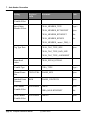
The following changes have been made to the eTPU+ chan_struct channel hardware
programming model from the baseline:
New fields are:
UDCMRWA
- Controls writing of erta register to the UDCM register.
Writing a value of 0 to this field triggers
the write to the UDCM register.
Modified fields are:
CIRC
Value
----0
- This field has been extended by 1 bit,
with this new bit treated as inverted.
The 3-bit CIRC field then has the following meanings:
~CIRC[2]
-------0
CIRC[1]
------0
CIRC[0]
------0
1
0
0
1
2
3
0
0
1
1
0
1
4
1
0
0
5
1
0
1
6
1
1
0
7
1
1
1
page 34, Compiler Reference Manual
Meaning
------channel interrupt request from
service channel [same as eTPU]
data transfer request from
service channel [same as eTPU]
global exception [same as eTPU]
do nothing; don't request
interrupt [same as eTPU]
channel interrupt request from
current channel
data transfer request from
current channel
channel interrupt & data
transfer request from current
channel
channel interrupt & data
transfer request from service
(C) 2007-2015
5. eTPU Programming Model
channel
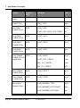
5.4.4
FLAG0
- Now testable for conditional jumps
FLAG1
- Now testable for conditional jumps
TDLA
- Now writeable (clearable) independent of TDLB
TDLB
- Now writeable (clearable) independent of TDLA
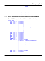
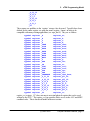
eTPU2 Extensions to the Channel Hardware Programming Model
For the eTPU2, chan_struct has been modified and extended to the following:
typedef struct {
CIRC
int :
ERWA
int :
ERWB
int :
FLC
int :
IPACA
int :
IPACB
int :
LSR
int :
MRLA
int :
MRLB
int :
MRLE
int :
MTD
int :
OPACA
int :
OPACB
int :
PDCM
int :
PIN
int :
TBSA
int :
TBSB
int :
TDL
int :
UDCMRWA int :
SMPR
int :
3
1
1
3
3
3
1
1
1
1
2
3
3
4
3
4
4
1
1
2
;
;
;
;
;
;
;
;
;
;
;
;
;
;
;
;
;
;
;
;
FLAG0
int : 1 ;
FLAG1
int : 1 ;
FM0
FM1
PSS
PSTI
PSTO
TDLA
TDLB
MRLEA
int
int
int
int
int
int
int
int
:
:
:
:
:
:
:
:
1
1
1
1
1
1
1
1
;
;
;
;
;
;
;
;
//
//
//
//
//
//
//
//
//
//
//
//
//
//
//
//
//
//
//
//
//
//
//
//
//
//
//
//
//
//
//
//
//
write-only
write-only
write-only
write-only
write-only
write-only
writeable, testable, entry condition
writeable, testable
writeable, testable
write-only
write-only
write-only
write-only
write-only
write-only
write-only
write-only
write-only
write-only
writeable, testable
[setting to -1 triggers semaphore free]
writeable (also via FLC),
testable, entry condition
writeable (also via FLC),
testable, entry condition
test-only
test-only
test-only
test-only
test-only
writeable, testable
writeable, testable
write-only
(C) 2007-2015
Compiler Reference Manual, page 35
5. eTPU Programming Model
MRLEB
int : 1 ;
} chan_struct;
// write-only
The following changes have been made to the eTPU2 chan_struct channel hardware
programming model from the eTPU+:
New fields are:
MRLEA
- Now writeable (clearable) independent of MRLEB
(MRLE still clears both latches)
MRLEB
- Now writeable (clearable) independent of MRLEA
(MRLE still clears both latches)
In order to allocate variable storage to eTPU2 engine-relative space, the address-space
type qualifier _Engine should be used.
5.4.5
Register Access
The eTPU has several special-purpose registers for which direct C-level access is
appropriate. In fact all registers can be accessed using the TR18037 named register
feature. The following named register keywords have been implemented in ETEC:
_A
_B
_C
_D
_CHAN
_DIOB
_ERTA
_ERTB
_LINK
_MACH
_MACL
_P
_RAR
_SR
_TCR1
_TCR2
_TPR
_TRR
_CHANBASE
_P_31_24
page 36, Compiler Reference Manual
(C) 2007-2015
5. eTPU Programming Model
_P_23_16
_P_15_8
_P_7_0
_P_31_16
_P_15_0
_P_31_0
_CC
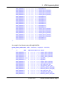
These names are qualifiers to the ‘register’ storage class keyword. Typedefs have been
defined for the entire register set, using the names register_<name> in order to be
compatible with many existing applications (see etpu_hw.h). They are as follows:
typedef
typedef
typedef
typedef
typedef
typedef
typedef
typedef
typedef
typedef
typedef
typedef
typedef
typedef
typedef
typedef
typedef
typedef
typedef
typedef
typedef
typedef
typedef
typedef
typedef
typedef
typedef
register
register
register
register
register
register
register
register
register
register
register
register
register
register
register
register
register
register
register
register
register
register
register
register
register
register
register
_A
_B
_C
_D
_CHAN
_DIOB
_ERTA
_ERTB
_LINK
_MACH
_MACL
_P
_RAR
_SR
_TCR1
_TCR2
_TPR
_TRR
_CHANBASE
_P_31_24
_P_23_16
_P_15_8
_P_7_0
_P_31_16
_P_15_0
_P_31_0
_CC
register_ac;
register_b;
register_c;
register_d;
register_chan;
register_diob;
register_erta;
register_ertb;
register_link;
register_mach;
register_macl;
register_p;
register_rar;
register_sr;
register_tcr1;
register_tcr2;
register_tpr;
register_trr;
register_chan_base;
register_p31_24;
register_p23_16;
register_p15_8;
register_p7_0;
register_p31_16;
register_p15_0;
register_p31_0;
register_cc;
register_cc (register _CC) does not map to an actual physical register that can be read/
written by the eTPU. The register_cc type provides direct access to the ALU and MDU
condition codes. This is discussed further in the next section.
(C) 2007-2015
Compiler Reference Manual, page 37
5. eTPU Programming Model
The register_chan_base (register _CHANBASE) type provides a way to specify a
channel relative pointer.
For the most part, the variables of the general purpose register types should not need to be
declared (e.g. a, p, diob, b, c, d, sr, macl, mach). In some cases variables of these registers
act as aliases only – they do not allocate them for the sole use of the variable (e.g. p).
However, registers a, b, c, d, diob and sr can be allocated directly by the user, locking out
the compiler from using them (except stack access can override b & diob). This capability
should be used very carefully as it can prevent the compiler from generating code resulting
in compilation errors.
An important difference between named register variables declared in a function scope,
and local variables which the compiler assigns to registers, occurs on function calls.
Named register variables are not saved/restored to prevent overwriting by the called
function; instead they are treated as if they have a global scope. True local variables, on
the other hand, are saved/restored if necessary when function calls are made.
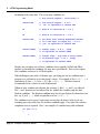
The special purpose registers need to frequently be directly accessed, and are therefore
are declared in the ETpu_Hw.h header file as follows:
register_chan
register_erta
register_erta
register_ertb
register_ertb
register_tcr1
register_tcr2
register_tpr
register_trr
register_link
5.4.6
chan
erta
ertA
ertb
ertB
tcr1
tcr2
tpr
trr
link
;
;
;
;
;
;
;
;
;
;
//
//
//
//
//
//
//
//
//
//
5 bits
24 bits
24 bits
24 bits
24 bits
24 bits
24 bits
16 bits
24 bits
8 bits
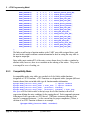
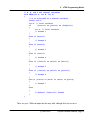
ALU Condition Code Access
Although best to avoid as a general coding practice, the ALU and MDU condition codes
can be accessed (tested) directly via _CC (register_cc). The comment in ETpu_Hw.h
best describes this feature:
// register_cc type
// of the following
// typedef struct {
//
unsigned int
//
unsigned int
//
unsigned int
//
unsigned int
is syntactically accessed like a struct (bitfield)
declaration:
V
N
C
Z
:
:
:
:
page 38, Compiler Reference Manual
1;
1;
1;
1;
//
//
//
//
ALU
ALU
ALU
ALU
overflow condition code
negative condition code
carry condition code
zero condition code
(C) 2007-2015
5. eTPU Programming Model
//
unsigned int
//
unsigned int
//
unsigned int
//
unsigned int
//
unsigned int
//
unsigned int
// } register_cc;
5.4.7
MV : 1;
MN : 1;
MC : 1;
MZ : 1;
MB : 1;
SMCLK :
//
//
//
//
//
1;
MDU overflow condition code
MDU negative condition code
MDU carry condition code
MDU zero condition code
MDU busy flag
// semaphore locked flag
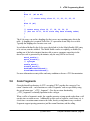
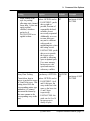
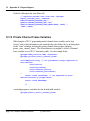
Built-in / Intrinsic Functions
This section covers available built-in/library/intrinsic functions available in ETEC.
5.4.7.1
Compatibility Functions
The following built-in functions provide user control of eTPU hardware settings &
features, but generate no code; they provide compatibility with existing solutions.
match_enable() - when called out in a thread, it causes matches to be enabled during the
thread by setting the match enable bit in the entry table for all vectors pointed at the thread.
Note that threads default to matches enabled. Not needed in ETEC enhanced mode.
match_disable() - when called out in a thread, it causes matches to be disabled during the
thread by setting the match enable bit in the entry table for all vectors pointed at the thread.
Note that threads default to matches enabled. Not needed in ETEC enhanced mode.
preload_p01() - when called out in an eTPU-C thread, specifies that the low preload entry
option is to be used - this means p gets loaded with the data at channel frame address 0 (32
bits), and diob gets loaded with the data at channel frame address 5 (24 bits). The default
is to let the tools decide which preload results in the best code (recommended). In ETEC
mode, the preload is specified by specifying a second parameter to the eTPU thread,
"_eTPU_preload_low" or "_eTPU_preload_high".
preload_p23() - when called out in an eTPU-C thread, specifies that the high preload entry
option is to be used - this means p gets loaded with the data at channel frame address 8 (32
bits), and diob gets loaded with the data at channel frame address 13 (24 bits). The default
is to let the tools decide which preload results in the best code (recommended). In ETEC
mode, the preload is specified by specifying a second parameter to the eTPU thread,
"_eTPU_preload_low" or "_eTPU_preload_high".
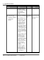
Functions that affect code generation:
read_mer() – triggers the contents of the A and B match registers to be transferred into
(C) 2007-2015
Compiler Reference Manual, page 39
5. eTPU Programming Model
the erta/ertb registers.
NOP() – injects a no-op opcode into the code stream that does not get optimized out.
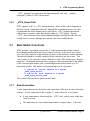
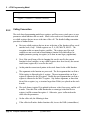
5.4.7.2
ETEC Coherency & Synchronization Control
These next set of functions allow users clearly state their needs in terms of coherency,
ordering, etc.
_AtomicBegin(), _AtomicEnd() - code located between a pair of these calls will be packed
into a single opcode; if this cannot be done a compilation error results. Another side-effect
of these stomic regions is that the optimizer will not optimize the code out, or move any of
the sub-instructiosn apart from each other. Other sub-instructions may be optimized into
the atomic opcode. See also 11.1.4 for pragmas that provide the same capability.
_SynchBoundaryAll() – disables any code from moving across the boundary during the
optimization process. See 11.1.5 for the matching pragma definition.
TBD – a bunch of additional stuff to control coherency, ordering.
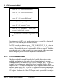
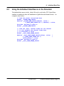
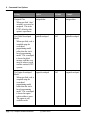
5.4.7.3
TR18037 Fixed-point Library Support
_Fract support includes a portion of the fixed-point library specified in TR 18037, as well as
some extensions. Supported functions are:
int mulir(int, _Fract) – under ordinary arithmetic conversion rules the result of a
multiplication of an integer and a _Fract is a _Fract. There are applications where instead
the desired result is the integer portion of the result; this library function provides that
capability.
unsigned int muliur(unsigned int, unsigned _Fract) – unsigned version.
Other versions to support 8 and 16 bit int-fract multiplication:
int8 muli8r8(int8, fract8);
unsigned int8 muli8ur8(unsigned int8, unsigned fract8);
int16 muli16r16(int16, fract16);
unsigned int16 muli16ur16(unsigned int16, unsigned fract16);
page 40, Compiler Reference Manual
(C) 2007-2015
5. eTPU Programming Model
int24 muli24r8(int24, fract8);
unsigned int24 muli24ur8(unsigned int24, unsigned fract8);
int24 muli24r16(int24, fract16);
unsigned int24 muli24ur16(unsigned int24, unsigned fract16);
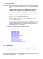
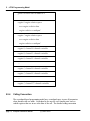
5.4.7.4
ALU/MDU Intrinsics
The eTPU has a number of hardware features that are not directly accessible via standard
C syntax. The intrinsics defined here provide C function-like access to these capabilities.
The eTPU Reference Manual should be consulted for additional details, particularly as
related to condition code calculations.
5.4.7.4.1 Rotate Right Support
// Rotate right by 1 bit the lower 8 bits
// ( result[6:0] = v[7:1]; result[7] = v[0];
//
result[23:8] = v[23:8]; )
// Condition code flags are sampled on 8 bits.
int24 __rotate_right_1_b7_0(int24 v);
// Rotate right by 1 bit the lower 16 bits
// ( result[14:0] = v[15:1]; result[15] = v[0];
//
result[23:16] = v[23:16]; )
// Condition code flags are sampled on 16 bits.
int24 __rotate_right_1_b15_0(int24 v);
// Rotate right by 1 bit all 24 bits
// ( result[22:0] = v[23:1]; result[23] = v[0]; )
// Condition code flags are sampled on 24 bits.
int24 __rotate_right_1(int24 v);
// Rotate the 24-bit value v
// to the right by 2^(bitexp+1) bits,
// where bitexp can be
// 0, 1, 2 or 3.
// Condition code flags are sampled
// per _sfXX extension, if used.
// See eTPU reference manual for details
// on condition code computation
// with multi-bit rotate.
int24 __rotate_right_2n(int24 v, int24 bitexp);
int24 __rotate_right_2n_sf8(int24 v, int24 bitexp);
(C) 2007-2015
Compiler Reference Manual, page 41
5. eTPU Programming Model
int24 __rotate_right_2n_sf16(int24 v, int24 bitexp);
int24 __rotate_right_2n_sf24(int24 v, int24 bitexp);
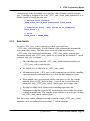
5.4.7.4.2 Absolute Value Support
// Compute the absolute value of v.
// Condition code flags are sampled
// per _sfXX extension, if used.
// See eTPU reference manual for details
// on condition code computation with absolute value.
int24 __abs(int24 v);
int24 __abs_sf8(int24 v);
int24 __abs_sf16(int24 v);
int24 __abs_sf24(int24 v);
5.4.7.4.3 Shift Register Support
// Shift the SR register right one bit.
void __shift_right_SR();
// Shift v right by one bit and return it.
// Register SR also gets shifted right by one
// bit and SR bit 23 gets the bit shifted out of v.
// Condition code flags are sampled
// per _sfXX extension, if used.
// See eTPU reference manual for details
// on condition code computation with add/shift right
int24 __shift_right_SR48(int24 v);
int24 __shift_right_SR48_sf8(int24 v);
int24 __shift_right_SR48_sf16(int24 v);
int24 __shift_right_SR48_sf24(int24 v);
5.4.7.4.4 Shift By 2(N+1) Support
// Shift 24-bit value v left or right by 2^(bitexp+1) bits,
// where bitexp can be
// 0, 1, 2 or 3.
// Condition code flags are sampled
// per _sfXX extension, if used.
// See eTPU reference manual for details
// on condition code computation with multi-bit rotate.
int24 __shift_left_2n(int24 v, int24 bitexp);
int24 __shift_left_2n_sf8(int24 v, int24 bitexp);
int24 __shift_left_2n_sf16(int24 v, int24 bitexp);
page 42, Compiler Reference Manual
(C) 2007-2015
5. eTPU Programming Model
int24
int24
int24
int24
int24
__shift_left_2n_sf24(int24 v, int24 bitexp);
__shift_right_2n(int24 v, int24 bitexp);
__shift_right_2n_sf8(int24 v, int24 bitexp);
__shift_right_2n_sf16(int24 v, int24 bitexp);
__shift_right_2n_sf24(int24 v, int24 bitexp);
5.4.7.4.5 Set/Clear Bit Support
// Set or clear (bitval==0 -> clear, bitval==1 -> set)
// the bit specified by bitnum in v.
// If revbitnum is not equal to 0,
// then the updated bit is actually 31 - bitnum.
// Condition code flags are sampled per _sfXX extension,
// if used.
// See eTPU reference manual for details on condition code
// computation with bit set/clear.
int24 __bit_n_update(int24 v, int24 bitnum,
int bitval, int revbitnum);
int24 __bit_n_update_sf8(int24 v, int24 bitnum,
int bitval, int revbitnum);
int24 __bit_n_update_sf16(int24 v, int24 bitnum,
int bitval, int revbitnum);
int24 __bit_n_update_sf24(int24 v, int24 bitnum,
int bitval, int revbitnum);
5.4.7.4.6 Exchange Bit Support
// Exchange the bit in v specified by the bitnum
// with C condition code flag.
// If revbitnum is not equal to 0, then the updated bit
// is actually 31 - bitnum rather then bitnum.
// Condition code flags are sampled per _sfXX extension,
// if used.
// See eTPU reference manual for details on condition code
// computation with bit exchange.
int24 __bit_n_exchange_C(int24 v, int24 bitnum,
int revbitnum);
int24 __bit_n_exchange_C_sf8(int24 v, int24 bitnum,
int revbitnum);
int24 __bit_n_exchange_C_sf16(int24 v, int24 bitnum,
int revbitnum);
int24 __bit_n_exchange_C_sf24(int24 v, int24 bitnum,
int revbitnum);
(C) 2007-2015
Compiler Reference Manual, page 43
5. eTPU Programming Model
5.4.7.4.7 MAC/MDU Support
All MAC/MDU intrinsic functions include a spin-while-busy loop after the operation is
begun. The optimizer will attempt to fill the pipeline with non-dependent opcodes and
eliminate the spin loop.
// Signed multiplication, with second argument 8, 16, or 24 bit
// {mach,macl} = x * y
void __mults8(int24 x, int8 y);
void __mults16(int24 x, int16 y);
void __mults24(int24 x, int24 y);
// Unsigned mutliplication, with second argument 8, 16, or 24 bit
void __multu8(unsigned int24 x, unsigned int8 y);
void __multu16(unsigned int24 x, unsigned int16 y);
void __multu24(unsigned int24 x, unsigned int24 y);
// Signed 24-bit multiply-accumulate.
// {mach,macl} += x * y
void __macs(int24 x, int24 y);
// Unsigned 24-bit multiply-accumulate.
// {mach,macl} += x * y
void __macu(unsigned int24 x, unsigned int24 y);
// Multiply signed value x and unsigned 8-bit fractional value f. The
mantissa
// portion of the result ends up in mach, and the fractional portion ends
in macl.
void __fmults8(int24 x, unsigned fract8 f);
// Multiply signed value x and unsigned 16-bit fractional value f. The
mantissa
// portion of the result ends up in mach, and the fractional portion ends
in macl.
void __fmults16(int24 x, unsigned fract16 f);
// Multiply unsigned value x and unsigned 8-bit fractional value f. The
mantissa
// portion of the result ends up in mach, and the fractional portion ends
in macl.
void __fmultu8(unsigned int24 x, unsigned fract8 f);
// Multiply unsigned value x and unsigned 16-bit fractional value f. The
mantissa
// portion of the result ends up in mach, and the fractional portion ends
in macl.
void __fmultu16(unsigned int24 x, unsigned fract16 f);
// Unsigned division, 24 bit / 8,16,24 bit
// {macl} = x / y, {mach} = remainder
void __divu8(unsigned int24 x, unsigned int8 y);
void __divu16(unsigned int24 x, unsigned int16 y);
void __divu24(unsigned int24 x, unsigned int24 y);
page 44, Compiler Reference Manual
(C) 2007-2015
up
up
up
up
5. eTPU Programming Model
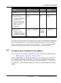
5.5
ETEC eTPU Class
The ETEC programming model for the eTPU uses some minor extensions to the C
language in order to cleanly match the eTPU hardware. A class-like syntax is used to link
together all the pieces that apply to a single eTPU channel, or group of eTPU channels that
must work in concert and share a channel frame. This class-like syntax, referred to as an
“eTPU class”, is used to aggregate the data and code that is used to perform a single
eTPU function/application. While similar in syntax to a C++ class, it is a much simplified
version in that there are no concepts like overloading, public/private, or derivation
supported. Rather it acts as a way to aggregate all the necessary pieces of an eTPU
application (typically maps to one channel, but can map to multiple channels) into a clean
package. These pieces consist of three main things. The data is called the “channel
frame”, or channel frame variables. In the eTPU programming model, there is a static
copy of the channel frame for each channel, or set of channels, to which the eTPU class is
assigned. The assignment itself is done via a combination of the channel function select
register (CFSR) and allocating room for the channel frame in SDM (SPRAM) and
properly setting the channel parameter base address (CPBA).
The second piece of an eTPU class is the set of C functions associated with it. These
take two flavors, either “eTPU threads” or class methods. eTPU threads are C functions
that are activated directly by eTPU entry conditions, and when they end they relinquish
control back to the eTPU scheduler. Only eTPU threads may be referenced in an entry
table, and they may not be called by any other functions. eTPU threads do not actually
return any value, and they take one dummy parameter that specifies whether matches are
enabled or disabled during thread processing. Since no parameter variable is actually
defined, just specifying the match type is sufficient. On the other hand, class methods are
regular callable C functions, but they may access channel frame variables as if they were
local variables to the function. Global eTPU threads and functions are allowed, although
they have no direct access to channel frame variables. They are defined like C functions
without any class scoping reference. Note that on eTPU/eTPU+ hardware global eTPU
threads cannot generate code that requires the stack, as such a thread does not have
knowledge of the stack base.
eTPU thread functions take one parameter type that defines whether matches are disabled
or enabled during thread processing. In other words, the parameter affects the entry
Match Enable (ME) setting. The new keywords that support this are
"_eTPU_matches_disabled" and "_eTPU_matches_enabled". It is generally
recommended that users write their functions/threads in such a way that matches can be
enabled during thread processing. If possible, only initialization & shutdown threads should
have matches disabled. A second, optional parameter type explicitly controls the preload
(C) 2007-2015
Compiler Reference Manual, page 45
5. eTPU Programming Model
setting for the thread - the preload setting is the (PP) Preload Parameter bit in an entry. If
this second parameter is not specified, then the preload is left to the compiler/linker to set,
which it does in the most optimal way (recommended). However, to explicitly control the
preload, the new type keywords are "_eTPU_preload_low" and "_eTPU_preload_high".
The last main piece of an eTPU class is the entry table definition. A class may be
associated with one or more eTPU entry tables, each of which has a unique eTPU
function number. These entry tables are defined like initialized arrays and the user must
explicitly specify an eTPU thread for each of the 32 different entry conditions allowed per
table. As part of the entry table definition, table qualifiers such as type (standard or
alternate), pin direction, and CFSR (function number) value are specified.
The example below shows the overall eTPU class syntax:
_eTPU_class ClassName
{
// channel frame variable(s)
int24 _data24;
// thread(s)
_eTPU_thread Initialize(_eTPU_matches_disabled);
_eTPU_thread HandleMatch(_eTPU_matches_enabled,
_eTPU_preload_high);
// method(s)
int24 CalculateOutput(int24 input1, int24 input2);
// entry table(s)
// entry table characteristics
// (standard vs. alternate, etc.)
// are defined at definition time
_eTPU_entry_table EntryTableName;
};
_eTPU_thread ClassName::Initialize(_eTPU_matches_disabled)
{
// …
_data24 = tcr1;
// …
}
_eTPU_thread ClassName::HandleMatch(_eTPU_matches_enabled,
_eTPU_preload_high)
page 46, Compiler Reference Manual
(C) 2007-2015
5. eTPU Programming Model
{
// …
_data24 = CalculateOutput(erta, data24);
// …
}
int24 ClassName::CalculateOutput(int24 input1, int24
input2)
{
// class method can directly access channel variables
return input1 + input2 + _data24;
}
The entry table definition is not shown here, but is covered in the detail in proceeding
sections.
eTPU classes have the additional feature of being able declare components of the class to
have public or private visibility. By default, all elements of an eTPU class are public. The
visibility is controlled with the "public" and "private" keywords, much like in C++. Items get
their visibility setting based on the nearest visibility keyword declared above them, or are
"public" if no visibility keywords are present. Currently the visibility setting only applies to
data (channel frame variables) and whether their interface information is exported into the
auto-defines and auto-struct files. Private data is not referenced in the generated autodefines and/or auto-struct. Below is an example class definition showing this feature.
_eTPU_class Test
{
public:
int r1;
int r2;
int r3;
int r4;
private:
int op1;
int op2;
int op3;
public:
int
int
int
int
r5;
r6;
r7;
r8;
(C) 2007-2015
Compiler Reference Manual, page 47
5. eTPU Programming Model
private:
int op4;
int8 op5;
int16 op6;
struct S op7;
// methods
// threads
_eTPU_thread Main(_eTPU_matches_enabled);
// entry tables
_eTPU_entry_table Test;
};
The channel frame variables r1 - r8 are public and their location information will be output
in the auto-defines and auto-struct files. The opN variables are private and will not be
exposed in the auto-generated interface files.
The ETEC compiler supports an alternative syntax for thread declarations. The
"_eTPU_thread" keyword can be used interchangeably with "void __attribute__
((interrupt_handler))", which is a GNU-based syntax.
5.5.1
Extension Syntax Details
The ETEC syntax extensions have been added into the C99 grammar as follows:
Several productions have been added to type-specifier:
type-specifier:
etpu-class-specifier
_eTPU_thread
_eTPU_entry_table
// only to be used in thread
_eTPU_matches_enabled
// only to be used in thread
_eTPU_matches_disabled
// only to be used in thread
_eTPU_preload_low
// only to be used in thread
_eTPU_preload_high
page 48, Compiler Reference Manual
(C) 2007-2015
declaration / definition
declaration / definition
declaration / definition
declaration / definition
5. eTPU Programming Model
etpu-class-specifier:
// function declarators are
//allowed in the struct-declaration-list
_eTPU_class identifier { struct-declaration-list }
The following production has been added to declarator:
declarator:
scope director-declarator
scope:
scope-name ::
scope-name:
identifier
// eTPU class name
The following productions have been added to type-qualifier – they can only apply to the
_eTPU_entry_table type:
Type-qualifier:
_eTPU_standard_ET
_eTPU_alternate_ET
_eTPU_inputpin_ET
_eTPU_outputpin_ET
_eTPU_cfsr_[0-31]_ET
_eTPU_cfsr_autocfsr_ET
In order to support the public/private feature, two productions have been added to
struct_declaration:
struct_declaration
specifier_qualifier_list struct_declarator_list ';'
'public' ':'
'private' ':'
(C) 2007-2015
Compiler Reference Manual, page 49
5. eTPU Programming Model
5.5.2
Native ETEC Format
The entry table definition takes the form of an array initializer, with a total of 32 entries,
one for each possible unique entry. The entry table is qualified by whether it is alternate or
standard, whether it is based upon an input or output pin value, and what channel function
select number it should be assigned. The input/output setting generates a #define in the
auto header for use during host initialization of the eTPU; note that some microcontrollers
only support an input pin setting. It does not actually affect eTPU code generation. The
entry table will be given the specified function number, unless during link a conflict is found
in which case linking fails. If no function number is specified (autocfsr), the linking process
automatically assigns a function number. Each entry vector is specified by its entry
conditions, and the thread activated by those conditions. Vectors may be specified in any
order as long as the complete set of 32 is defined. To simplify the entry table definition,
several macros have been defined. The first begins the table definition:
#define DEFINE_ENTRY_TABLE(className, tableName, tableType, pinDirection, cfsrValue)
The className and tableName must match the names used in the class declaration. The
tableType parameter must be standard or alternate . The pinDirection argument can be
either inputpin or outputpin. Finally, the cfsrValue can be either a number from [0-31],
or it can be autocfsr, in which case the linker assigns the entry table a CFSR value.
Then, three different macros are used to specify each entry vector. Three are required
since depending upon entry table type, up to 3 HSR values can contribute to the entry.
#define ETPU_VECTOR1(hsr1, lsr, m1, m2, pin, flag0, flag1, threadName)
#define ETPU_VECTOR2(hsr1, hsr2, lsr, m1, m2, pin, flag0, flag1, threadName)
#define ETPU_VECTOR3(hsr1, hsr2, hsr3, lsr, m1, m2, pin, flag0, flag1, threadName)
Below is an example of the definition of a standard entry table with a user-specified CFSR
value.
DEFINE_ENTRY_TABLE(ClassName, EntryTableName, standard, inputpin, 3)
{
//
HSR LSR M1 M2 PIN F0 F1 vector
ETPU_VECTOR1(1, x, x, x, 0, 0, x, Initialize),
ETPU_VECTOR1(1, x, x, x, 0, 1, x, Initialize),
ETPU_VECTOR1(1, x, x, x, 1, 0, x, Initialize),
ETPU_VECTOR1(1, x, x, x, 1, 1, x, Initialize),
ETPU_VECTOR1(2, x, x, x, x, x, x, Global_Error_Thread),
ETPU_VECTOR1(3, x, x, x, x, x, x, Global_Error_Thread),
ETPU_VECTOR1(4, x, x, x, x, x, x, Global_Error_Thread),
ETPU_VECTOR1(5, x, x, x, x, x, x, Global_Error_Thread),
ETPU_VECTOR1(6, x, x, x, x, x, x, Global_Error_Thread),
ETPU_VECTOR1(7, x, x, x, x, x, x, Global_Error_Thread),
ETPU_VECTOR1(0, 1, 1, 1, x, 0, x, HandleMatch),
page 50, Compiler Reference Manual
(C) 2007-2015
5. eTPU Programming Model
ETPU_VECTOR1(0,
ETPU_VECTOR1(0,
ETPU_VECTOR1(0,
ETPU_VECTOR1(0,
ETPU_VECTOR1(0,
ETPU_VECTOR1(0,
ETPU_VECTOR1(0,
ETPU_VECTOR1(0,
ETPU_VECTOR1(0,
ETPU_VECTOR1(0,
ETPU_VECTOR1(0,
ETPU_VECTOR1(0,
ETPU_VECTOR1(0,
ETPU_VECTOR1(0,
ETPU_VECTOR1(0,
ETPU_VECTOR1(0,
ETPU_VECTOR1(0,
ETPU_VECTOR1(0,
ETPU_VECTOR1(0,
ETPU_VECTOR1(0,
ETPU_VECTOR1(0,
1,
0,
0,
0,
0,
0,
0,
0,
0,
0,
0,
0,
0,
1,
1,
1,
1,
1,
1,
1,
1,
1,
0,
0,
0,
0,
1,
1,
1,
1,
1,
1,
1,
1,
0,
0,
0,
0,
0,
0,
1,
1,
1,
1,
1,
1,
1,
0,
0,
0,
0,
1,
1,
1,
1,
0,
0,
0,
0,
1,
1,
0,
0,
x,
0,
0,
1,
1,
0,
0,
1,
1,
0,
0,
1,
1,
0,
0,
1,
1,
x,
x,
x,
x,
1,
0,
1,
0,
1,
0,
1,
0,
1,
0,
1,
0,
1,
0,
1,
0,
1,
0,
1,
0,
1,
x,
x,
x,
x,
x,
x,
x,
x,
x,
x,
x,
x,
x,
x,
x,
x,
x,
x,
x,
x,
x,
HandleMatch),
Global_Error_Thread),
Global_Error_Thread),
Global_Error_Thread),
Global_Error_Thread),
HandleMatch),
HandleMatch),
HandleMatch),
HandleMatch),
HandleMatch),
HandleMatch),
HandleMatch),
HandleMatch),
Global_Error_Thread),
Global_Error_Thread),
Global_Error_Thread),
Global_Error_Thread),
Global_Error_Thread),
Global_Error_Thread),
HandleMatch),
HandleMatch),
};
An example of an alternate entry table might look like:
DEFINE_ENTRY_TABLE(UART, UART,
{
//
HSR
LSR
ETPU_VECTOR2(2,3,
x,
ETPU_VECTOR2(2,3,
x,
ETPU_VECTOR2(2,3,
x,
ETPU_VECTOR2(2,3,
x,
ETPU_VECTOR3(1,4,5, x,
ETPU_VECTOR2(6,7,
x,
ETPU_VECTOR1(0,
1,
ETPU_VECTOR1(0,
1,
ETPU_VECTOR1(0,
x,
ETPU_VECTOR1(0,
x,
ETPU_VECTOR1(0,
x,
ETPU_VECTOR1(0,
x,
ETPU_VECTOR1(0,
x,
ETPU_VECTOR1(0,
x,
ETPU_VECTOR1(0,
x,
alternate, outputpin, autocfsr)
M1
x,
x,
x,
x,
x,
x,
0,
0,
1,
1,
1,
1,
1,
1,
1,
M2
x,
x,
x,
x,
x,
x,
0,
0,
0,
0,
0,
0,
0,
0,
0,
PIN
0,
0,
1,
1,
x,
x,
0,
1,
0,
0,
0,
0,
1,
1,
1,
(C) 2007-2015
F0
0,
1,
0,
1,
x,
x,
x,
x,
0,
1,
0,
1,
0,
1,
0,
F1
x,
x,
x,
x,
x,
x,
x,
x,
0,
0,
1,
1,
0,
0,
1,
vector
Global_Error_Thread),
Global_Error_Thread),
Global_Error_Thread),
Global_Error_Thread),
TX_INIT),
RX_INIT),
Global_Error_Thread),
Global_Error_Thread),
Test_New_Data_TX),
Send_Serial_Data_TX),
Receive_Serial_Data_RX),
Receive_Serial_Data_RX),
Test_New_Data_TX),
Send_Serial_Data_TX),
Receive_Serial_Data_RX),
Compiler Reference Manual, page 51
5. eTPU Programming Model
ETPU_VECTOR1(0,
ETPU_VECTOR1(0,
ETPU_VECTOR1(0,
ETPU_VECTOR1(0,
ETPU_VECTOR1(0,
ETPU_VECTOR1(0,
ETPU_VECTOR1(0,
ETPU_VECTOR1(0,
ETPU_VECTOR1(0,
ETPU_VECTOR1(0,
ETPU_VECTOR1(0,
ETPU_VECTOR1(0,
ETPU_VECTOR1(0,
ETPU_VECTOR1(0,
ETPU_VECTOR1(0,
ETPU_VECTOR1(0,
ETPU_VECTOR1(0,
x,
x,
x,
x,
x,
x,
x,
x,
x,
x,
x,
x,
x,
x,
x,
x,
x,
1,
0,
0,
0,
0,
0,
0,
0,
0,
1,
1,
1,
1,
1,
1,
1,
1,
0,
1,
1,
1,
1,
1,
1,
1,
1,
1,
1,
1,
1,
1,
1,
1,
1,
1,
0,
0,
0,
0,
1,
1,
1,
1,
0,
0,
0,
0,
1,
1,
1,
1,
1,
0,
1,
0,
1,
0,
1,
0,
1,
0,
1,
0,
1,
0,
1,
0,
1,
1,
0,
0,
1,
1,
0,
0,
1,
1,
0,
0,
1,
1,
0,
0,
1,
1,
Receive_Serial_Data_RX),
Global_Error_Thread),
Global_Error_Thread),
Detect_New_Data_RX),
Detect_New_Data_RX),
Global_Error_Thread),
Global_Error_Thread),
Detect_New_Data_RX),
Detect_New_Data_RX),
Test_New_Data_TX),
Send_Serial_Data_TX),
Detect_New_Data_RX),
Detect_New_Data_RX),
Test_New_Data_TX),
Send_Serial_Data_TX),
Detect_New_Data_RX),
Detect_New_Data_RX),
};
The linker would assign a function number to the UART entry table assigned above, and
the auto-header output would not contain information for host on setting the entry table to
the input or output pin.
Entry tables must contain all 32 of the entry vectors shown above for either a standard or
alternate table, however, there is no constraint on the ordering of the entries. They can be
re-arranged for ease of reading, etc.
5.5.3
Compatibility Mode
In compatibility mode, entry tables are encoded via if-else blocks within functions
designated as eTPU Functions. eTPU Functions are designated with a #pragma (different
formats shown) that can include table type & function number information:
#pragma ETPU_function
#pragma ETPU_function
#pragma ETPU_function
#pragma ETPU_function
The speci al if-else block
<func_name>;
<func_name> @ <func_num>;
<func_name>, [alternate |
<func_name>, [alternate |
// implies standard
// implies standard
standard];
standard] @ <func_num>;
resides at the top scope level of the function, with each if
expression defining the entry conditions for the ensuing thread. Each compound statement
following an if/else represents an eTPU thread. [TBD note: statement following if/else
must be a compound statement { } at the current time for proper compilation.] Below, a
skeleton of an eTPU Function is shown as an example.
#pragma ETPU_function TEST, standard;
page 52, Compiler Reference Manual
(C) 2007-2015
5. eTPU Programming Model
// A, B, and C are channel variables
void TEST(int A, int B, int C)
{
// D is allocated as a channel variable
static int D;
int E; // local variable
if
((hsr==1) && (pin==0) && (flag0==0))
{
int F; // local variable
// thread 1
}
else if (hsr==1)
{
// thread 2
}
else if (hsr==2)
{
// thread 3
}
else if (lsr==1)
{
// thread 4
}
else if ((lsr==0) && (m1==0) && (m2==1))
{
// thread 5
}
else if ((lsr==0) && (m1==1) && (pin==0))
{
// thread 6
}
else if ((lsr==0) && (m1==1) && (m2==0) && (pin==1))
{
// thread 7
}
else
{
// default "catch-all" thread
}
}
There are up to 7 different inputs into the entry table, although all seven are never
(C) 2007-2015
Compiler Reference Manual, page 53
5. eTPU Programming Model
meaningful at the same time. The seven entry conditions are:
hsr
// host service request – valid value 1-7
channel.LSR
// link service request – 0 or 1;
// ‘lsr’ is equivalent to channel.LSR
m1
// match A or transition B – 0 or 1
m2
// match B or transition A – 0 or 1
channel.PIN
// pin value (host setting determines whether
// it is the input or output pin) – 0 or 1;
// ‘pin’ is equivalent to channel.PIN
channel.FLAG0
// channel flag0 – 0 or 1; ‘flag0’
// is equivalent to channel.FLAG0
channel.FLAG1
// channel flag1 – only used in entry tables
// of alternate type – 0 or 1; ‘flag1’
// is equivalent to channel.FLAG1
Besides one exception, tests of these conditions can be logically ANDed and ORed
together to determine the conditions for entry into a given thread. Host service request
(hsr) conditions can never be ANDed together.
When defining an entry table of alternate type, specifying just one hsr condition from a
grouped set is sufficient to cover that group’s entries. For example, if (hsr == 1) { … } is
equivalent to if ((hsr == 1) || (hsr == 4) || (hsr == 5)) { … }. The latter format is
recommended as it is clearer to read & understand.
Within an entry condition specification, the operators ||, &&, !, ==, and != are allowed.
The != and ! operators are not allowed for use with the hsr condition, only the other
Boolean conditions. The Boolean conditions may also be specified just by themselves (not
hsr), e.g. if (m1) { … } which is equivalent to if (m1 == 1) { … }.
The conditions in successive if expressions can overlap; the latter if only covers any
remaining open entry table slots for which its conditions apply. If no open slots remain a
compilation error is reported. Here’s an example of a standard entry table definition:
If (hsr == 1)
{
page 54, Compiler Reference Manual
(C) 2007-2015
5. eTPU Programming Model
}
Else if (m1 && m2)
{
… // covers entry slots 10, 11, 20, 21, 22, 23
}
Else if (m1)
{
…
// covers entry slots 16, 17, 18, 19, 30, 31
// (but not 10-11, 20-23 since they were already taken)
}
The if-else array can end in a dangling else that covers any remaining entry slots in the
table. A dangling else is required if all of the ‘if’ expressions do not fully cover a table.
Typically the dangling else executes error code.
In each thread defined by the if-else array, the default is for the Match Enable (ME) entry
to be set true, matches enabled. The Match Enable can be set explicitly, or disabled, by
making one of the below intrinsic function calls or macro synonyms somewhere in the
thread (no code is generated by the intrinsic, only the entry ME bit is affected).
match_enable();
match_disable();
// synonyms
enable_match();
disable_match();
EnableMatchesInThread();
DisableMatchesInThread();
For more information on entry tables and entry conditions reference eTPU documentation.
5.6
Code Fragments
Given the thread-based nature of eTPU execution, ETEC provides the concept of “noreturn” function calls – such functions are called “fragments” and are specified by using
the special return type “_eTPU_fragment”. Give the no-return functionality,
_eTPU_fragment is essentially equivalent to the void type.
When a call to a fragment is made, the compiler generates a jump opcode rather than a call
opcode since no return occurs. Additionally, no state such as registers, stack frame, etc. is
saved since execution cannot return to the caller, thereby saving unnecessary overhead.
Fragments support passing parameters just like normal functions, and the calling
(C) 2007-2015
Compiler Reference Manual, page 55
5. eTPU Programming Model
conventions are the same except for the state save (on both caller and callee sides). Note
that on the fragment (callee) side, there is also reduced state saving – non-volatile registers
do not need to be saved, nor does the return address register. Internally, fragments work
just like any other C function – they can make calls, even to other fragments. A simple
example of using common initialization code is show below.
_eTPU_thread PPA::INIT_TCR1(_eTPU_matches_disabled)
{
/* set up time base for TCR1*/
ActionUnitA( MatchTCR1, CaptureTCR1, GreaterEqual);
CommonInit(); // no return from this call
}
_eTPU_thread PPA::INIT_TCR2(_eTPU_matches_disabled)
{
/* set up time base for TCR2 */
ActionUnitA( MatchTCR2, CaptureTCR2, GreaterEqual);
CommonInit(); // no return from this call
}
_eTPU_fragment PPA::CommonInit()
{
DisableOutputBuffer(); /* required for Puma */
// Needed so ouptut pin does not get toggled
OnMatchA(NoChange);
// Needed so ouptut pin does not get toggled
OnMatchB(NoChange);
ClearAllLatches();
Measurement = Inactive;
// Enable service request when first edge occurs
SingleMatchSingleTransition();
// ...
}
Note that the compiler will attempt to detect stranded code that follows a call to a
fragment, and issue a warning if it finds such code.
The ETEC compiler supports an alternative syntax for fragment declarations. The
page 56, Compiler Reference Manual
(C) 2007-2015
5. eTPU Programming Model
"_eTPU_fragment" keyword can be used interchangeably with "void __attribute__
((noreturn))", which is a GNU-based syntax.
5.6.1
_eTPU_thread Calls
ETEC supports “calls” to _eTPU_thread functions – these act like calls to fragments in
that they execute a jump rather than call. Although this is functional, in most cases it is
recommended that such common code be placed in an _eTPU_fragment instead and
called from two locations, rather than directly calling an _eTPU_thread. Threads
(_eTPU_thread functions) may contain additional prologue code that the caller does not
actually want to execute, although such code does not cause invalid behavior.
5.7
State Switch Constructs
ETEC provides a specialized version of the C switch statement that provides reduced
thread length operation and in most cases reduced code size, at the cost of user control
over state values and some of the robustness features of the standard C switch statement.
The tradeoffs should be carefully considered before choosing to use this feature. This
‘state switch’, as it is referred to, makes efficient use of the eTPU architecture’s dispatch
instruction. The dispatch instruction allows a jump (or call) to the instruction at the address
of the current program counter, plus a variable displacement which can be up to 255
instructions/opcodes. This feature is activated through two new keywords:
// similar to “switch” keyword in C syntax
_eTPU_state_switch
// similar to “enum” keyword in C syntax
_eTPU_state_switch_enum
The sections below provide the details on this feature.
5.7.1
State Enumeration
A state enumeration must be declared as only expressions of this type may be used in state
switches. A state enumeration is like a regular ‘C’ enum, with a few of exceptions.
A state enumeration is denoted with the ‘_eTPU_state_switch_enum’ rather than
‘enum’ keyword.
The enumerators in a state enumeration cannot be assigned values. Code such
(C) 2007-2015
Compiler Reference Manual, page 57
5. eTPU Programming Model
“_eTPU_state_switch_enum CrankState { STALL = 5, };” will result in a compile
error.
The enumerator values assigned by the compiler/linker may not match the ANSI
standard for C code, wherein they start at 0, and increment by 1 with each
successive enumerator. Rather, the compiler/linker assigns values such that the
dispatch instruction used for the matching _eTPU_state_switch works correctly.
_eTPU_state_switch_enum tag types (or typedef thereof) cannot be used in
typecasts. This is to prevent potentially dangerous code.
Variables declared with an _eTPU_state_switch_enum tag type are always
allocated as a single unsigned byte.
State enumeration literals must be unique among all the enumeration literals (state
or regular) of all the code that is to be linked together. This limitation is due to the
fact that the enumeration literals only get computed at link time and if the literals
are not uniquely named there can be clashes.
An example of a state enumeration type declaration is as follows:
_eTPU_state_switch_enum CrankStates
{
CRANK_SEEK,
CRANK_BLANK_TIME,
CRANK_BLANK_TEETH,
CRANK_FIRST_EDGE,
CRANK_SECOND_EDGE,
CRANK_TEST_POSSIBLE_GAP,
CRANK_VERIFY_GAP,
CRANK_GAP_VERIFIED,
CRANK_COUNTING,
CRANK_TOOTH_BEFORE_GAP,
CRANK_TOOTH_AFTER_GAP,
CRANK_TOOTH_AFTER_GAP_NOT_HRM
};
5.7.2
State Variable
A “state” variable must be declared with a state enumeration type. Variables of this
special tag type are 1 byte in size, and unlike variables of the standard enum tag type, strict
type checking is performed by the compiler. Such a state variable cannot be assigned to a
page 58, Compiler Reference Manual
(C) 2007-2015
5. eTPU Programming Model
constant integer value, for example, or assigned the value of another variable of integer
type. It can only be assigned to one of the _eTPU_state_switch_enum enumerators, or to
another variable of exactly the same type.
// declare state variable
_eTPU_state_switch_enum CrankStates Crank_State;
// compilation error – must assign to an enumerator
Crank_State = 0;
// valid
Crank_State = CRANK_SEEK;
5.7.3
State Switch
For each _eTPU_state_switch_enum tag type there can be up to one
_eTPU_state_switch statement. It is the contents of this statement that determine the
state (enumerator) values. The linker issues an error if it finds more than one
_eTPU_state_switch associated with the same _eTPU_state_switch_enum tag type.
Statements denoted with _eTPU_state_switch are very much like the standard ‘C’ switch
statement, with a few exceptions:
The controlling expression in an _eTPU_state_switch statement must have an
_eTPU_state_switch_enum tag type.
No ‘default’ case is allowed in an _eTPU_state_switch.
All enumerators in the _eTPU_state_switch_enum tag type used in the controlling
expression must be associated with a case, even if it does nothing but ‘break’.
When multiple cases are associated with the same piece of code, the compiler
implicitly inserts a NOP() between them – it must do this to ensure that each
enumerator is the _eTPU_state_switch_enum tag type gets a unique value.
No range or validity check is done on the controlling expression value.
Programmers using this feature MUST ensure that the state variable does not get
assigned an invalid value. The compiler assists with this via its strict type checking
on _eTPU_state_switch_enum tag types.
Note that a state variable, although it can only be used in a single _eTPU_state_switch
statement, can be used other places in a normal ‘C’ switch statement.
(C) 2007-2015
Compiler Reference Manual, page 59
5. eTPU Programming Model
An example of a state switch, shown in a listing file, is shown below (some code removed
for brevity). Note that every enumerator is covered by a case, and note the NOPs
inserted where multiple cases fall through to the same code.
0CF4: 0xCFEFF987
0CF8: 0xFFDFDEF9
0CFC: 0x000FA439
0D00: 0xCFFFF986
0D04: 0xBFEC2F87
:
0D08: 0x1F783FFF
0D0C: 0x58FFFE1F
:
0D10: 0x0FFF9FFF
:
0D14: 0xDFEFD984
:
_eTPU_state_switch (Crank_State)
ram
p_31_24 = *((channel int8 *) 0x1C);;
seq goto ProgramCounter + p_31_24, flush;;
{
case CRANK_BLANK_TIME:
// timeout is expected
Blank_Time_Expired_Flag = 1;
alu
p_31_24 = ((u24) 0)+0x1;;
ram
*((channel int8 *) 0x18) = p_31_24;;
// Timeout time
ertb = Tooth_Time + Blank_Time;
alu
ertA = tcr1+0x0;
ram
diob = *((channel int24 *) 0x1D);;
alu
ertB = p+diob;;
// schedule an immediate match to open the window
erta = tcr1;
ClearMatchALatch();
chan
clear MatchRecognitionLatchA, matchA = ertA,
set MatchEnableLatchA,
clear MatchRecognitionLatchB,
matchB = ertB, set MatchEnableLatchB,
detectA = off;;
ClearMatchBLatch();
WriteErtAToMatchAAndEnable();
WriteErtBToMatchBAndEnable();
// don't detect transition during blank time
OnTransA (NoDetect);
tcr2 = 0;
alu
tcr2 = ((u24) 0)+0x0;
seq
end;;
break;
case CRANK_BLANK_TEETH:
// schedule an immediate match
// to open the window
erta = tcr1;
// clear MatchB
// & don't set new match value
ClearMatchBLatch ();
ram
p_31_24 = *((channel int8 *) 0x10);
chan clear MatchRecognitionLatchB;;
// so it always enabled window is fully open
// MatchA is left pending;
// in this channel mode
// it doesn't request service
page 60, Compiler Reference Manual
(C) 2007-2015
5. eTPU Programming Model
0D18: 0x1EF2AFFF
0D1C: 0xCFFFF984
alu
ram
Blank_Tooth_Count--;
p_31_24 = p_31_24-0x0-1;;
*((channel int8 *) 0x10) = p_31_24;;
// < REMOVED>
0D34: 0xBFEF9F89
:
0D38: 0x1F783FFF
0D3C: 0x7FFFFF9F
0D40: 0x005FA439
0D44: 0xCFFFF987
case CRANK_FIRST_EDGE:
// Timeout time
ertb = Tooth_Time + First_Tooth_Timeout;
alu
tcr2 = ((u24) 0)+0x0;
ram
diob = *((channel int24 *) 0x25);;
alu
ertB = p+diob;;
WriteErtBToMatchBAndEnable();
chan clear MatchRecognitionLatchB, matchB = ertB,
set MatchEnableLatchB;;
ClearMatchBLatch();
Crank_State = CRANK_SECOND_EDGE;
alu
p_31_24 = ((u24) 0)+0x15;;
ram
*((channel int8 *) 0x1C) = p_31_24;;
tcr2 = 0;
// <REMOVED>
0D50: 0xBFEF9F95
:
0D54: 0xBC787B91
:
0D58: 0x009FA459
0D5C: 0xCFFFF987
case CRANK_SECOND_EDGE:
Tooth_Period_A = Tooth_Time - Last_Tooth_Time;
alu
tcr2 = ((u24) 0)+0x0;
ram
diob = *((channel int24 *) 0x55);;
alu
p = p-diob;
ram
*((channel int24 *) 0x45) = p_23_0;;
Crank_State = CRANK_TEST_POSSIBLE_GAP;
alu
p_31_24 = ((u24) 0)+0x26;;
ram
*((channel int8 *) 0x1C) = p_31_24;;
tcr2 = 0;
// <REMOVED>
0D94: 0xBFEFFF95
0D98: 0xBC787B93
:
case CRANK_TEST_POSSIBLE_GAP:
Tooth_Period_B = Tooth_Time - Last_Tooth_Time;
ram
diob = *((channel int24 *) 0x55);;
alu
p = p-diob;
ram
*((channel int24 *) 0x4D) = p_23_0;;
// <REMOVED>
0E4C: 0xBFEFFF95
0E50: 0xBC787B91
:
case CRANK_VERIFY_GAP:
Tooth_Period_A = Tooth_Time - Last_Tooth_Time;
ram
diob = *((channel int24 *) 0x55);;
alu
p = p-diob;
ram
*((channel int24 *) 0x45) = p_23_0;;
(C) 2007-2015
Compiler Reference Manual, page 61
5. eTPU Programming Model
0E54:
0E58:
0E5C:
0E60:
0E64:
0E68:
0E6C:
0xBFEFFB93
0xBFEFFF86
0x2F78FFE9
0xF3587307
0xBFEFFB91
0x1C17FEEF
0xF4D87607
ram
ram
alu
seq
ram
alu
seq
0E70: 0x01FFA459
0E74: 0xCFFFF987
alu
ram
// Gap is verified
if ( muliur(Tooth_Period_B, Gap_Ratio)
> Tooth_Period_A)
p_23_0 = *((channel int24 *) 0x4D);;
diob = *((channel int24 *) 0x19);;
mac = p * ((u24) diob);;
if MacBusy==true then goto 0xE60, flush;;
p_23_0 = *((channel int24 *) 0x45);;
nil = mach-p, SampleFlags;;
if LowerOrEqual==true then goto 0xEC0, flush;;
{
Crank_State = CRANK_GAP_VERIFIED;
p_31_24 = ((u24) 0)+0x7E;;
*((channel int8 *) 0x1C) = p_31_24;;
// <REMOVED>
0EF4: 0xCFEB3980
:
0EF8: 0x0002A439
0EFC: 0xCFFFF980
case CRANK_GAP_VERIFIED:
Tooth_Count++;
ram
p_31_24 = *((channel int8 *) 0x0);
chan set ChannelFlag1, set SvcdChan ChannelIntr;;
alu
p_31_24 = p_31_24+0x1;;
ram
*((channel int8 *) 0x0) = p_31_24;;
// <REMOVED>
0F40: 0x4FFFFFFF
0F44: 0x4FFFFFFF
0F48: 0x4FFFFFFF
0F4C: 0x4FFFFFFF
0F50: 0xCFEFF982
0F54: 0x0C42AB82
0F58: 0xC7FFF982
:
case
nop;;
case
nop;;
case
nop;;
case
nop;;
CRANK_SEEK:
CRANK_COUNTING:
CRANK_TOOTH_BEFORE_GAP:
CRANK_TOOTH_AFTER_GAP:
case CRANK_TOOTH_AFTER_GAP_NOT_HRM:
Error_Status = Error_Status
| CRANK_INTERNAL_ERROR;
ram
p_31_24 = *((channel int8 *) 0x8);;
alu
p_31_24 = p_31_24 | 0x10;;
ram
*((channel int8 *) 0x8) = p_31_24;
seq
end;;
break;
}
page 62, Compiler Reference Manual
(C) 2007-2015
5. eTPU Programming Model
5.7.4
Additional Notes
The compiler/linker calculated state enumeration values are output through all the
supported host interface mechanisms. For example, given the examples above, this is what
is output for the CrankStates state enumeration:
// defines for type _eTPU_state_switch_enum CrankStates
// size of a tag type
// value (sizeof) = _CHAN_TAG_TYPE_SIZE_CrankStates_
#define _CHAN_TAG_TYPE_SIZE_CrankStates_ 0x01
// values of the literals of an enum type
// value = _CHAN_ENUM_LITERAL_Crank_CrankStates_CRANK_SEEK_
#define _CHAN_ENUM_LITERAL_Crank_CrankStates_CRANK_SEEK_ 0x91
#define _CHAN_ENUM_LITERAL_Crank_CrankStates_CRANK_BLANK_TIME_ 0x00
#define _CHAN_ENUM_LITERAL_Crank_CrankStates_CRANK_BLANK_TEETH_ 0x06
#define _CHAN_ENUM_LITERAL_Crank_CrankStates_CRANK_FIRST_EDGE_ 0x0E
#define _CHAN_ENUM_LITERAL_Crank_CrankStates_CRANK_SECOND_EDGE_ 0x15
#define _CHAN_ENUM_LITERAL_Crank_CrankStates_CRANK_TEST_POSSIBLE_GAP_ 0x26
#define _CHAN_ENUM_LITERAL_Crank_CrankStates_CRANK_VERIFY_GAP_ 0x54
#define _CHAN_ENUM_LITERAL_Crank_CrankStates_CRANK_GAP_VERIFIED_ 0x7E
#define _CHAN_ENUM_LITERAL_Crank_CrankStates_CRANK_COUNTING_ 0x92
#define _CHAN_ENUM_LITERAL_Crank_CrankStates_CRANK_TOOTH_BEFORE_GAP_ 0x93
#define _CHAN_ENUM_LITERAL_Crank_CrankStates_CRANK_TOOTH_AFTER_GAP_ 0x94
#define _CHAN_ENUM_LITERAL_Crank_CrankStates_CRANK_TOOTH_AFTER_GAP_NOT_HRM_
0x95
If the code that makes up the state switch exceeds 255 opcodes, there may be some cases
that still require the dispatch jump plus a regular jump. Such cases can be minimized but
putting the most code-intensive case(s) at the end of the state switch.
The user can easily convert ETEC-specific state switch code to ANSI-compliant code by
utilizing macros such as:
#define _eTPU_state_switch switch
#define _eTPU_state_switch_enum enum
5.8
eTPU Constant Tables
The eTPU instruction set provides a fairly efficient way to create 24-bit constant lookup
tables in the code. These special lookup tables are not any more efficient than the use of a
regular C arrays for lookup tables, and in fact access is almost always slightly slower.
However, they do offer one key difference that can be advantageous in some cases - the
constant table is stored in the code memory rather than the data memory. If system being
programmed is out of data memory (SDM), but is not using all of code memory (SCM),
then the use of this constant lookup table construct can be very helpful. Below, the syntax
(C) 2007-2015
Compiler Reference Manual, page 63
5. eTPU Programming Model
and usage is described. For much more detail on eTPU constant lookup tables, including
how to perform run-time data calibration, please see the Assembler Reference Manual
Constant Lookup Table section.
In C code, constant tables are defined as arrays of the special type
'_eTPU_constant_table'. The arrays can be multi-dimensional. Typically an initializer
should be used to load the constant table. Any uninitialized array elements are given a
value of 0. When a 24-bit value is retrieved from the table, it is treated as a signed integer
by default. Type casting can be used to change to unsigned, _Fract (fractional), or
whatever type is desired.
// constant table definition (global)
_eTPU_constant_table sin_table[64] = { 0x000000,
0x034517, ... };
// external declaration for reference from other files
extern _eTPU_constant_table sin_table[64];
// multi-dimensional
_eTPU_constant_table switch_table[2][2] = { { 3, 2, }, { 1,
0 } };
// table static to a scope
static _eTPU_constant_table coef_table[8] = { 0x0,
0x200, ... };
Syntactically, accessing elements of the table is handled just like normal array element
access.
int coef = coef_table[index]; // get the coefficient
specified by index
fract24 sin_val = (fract24)sin_table[angle];
Because constant tables exist in code memory which is not writeable and utilize a special
eTPU microcode instruction, there are several limitations associated with them:
- tables can contain at most 256 elements
- because the table lives in immutable, inaccessible code memory, the only operation that
can be performed on the table symbol is a full array de-reference. No conversion to a
pointer or other operations.
- tables can only be defined at global scope, or static to a function scope
page 64, Compiler Reference Manual
(C) 2007-2015
5. eTPU Programming Model
5.9
ETEC Local Variable Model & Calling Conventions
When local variables are declared & used, they are allocated to available registers if
possible, but the resources are limited. The same situation arises when function calls with
parameters are made – some parameters may be passed by registers but again it is a very
limited resource on the eTPU. Thus local variables, parameters, and other data that needs
to be saved/restored on function calls must be kept somewhere in memory. The default
model that ETEC uses for this is a stack that builds upwards in memory as function calltree depth increases.
The stack approach allows any C code to compile and run without fail (within memory
limits), but in some cases may not generate as optimal code as that compiled using a
“scratchpad” model. ETEC supports “–globalScratchpad” “-engineScratchpad” options to
enable compilation with this model. When scratchpad is enabled and data overflows
registers, rather than go onto a dynamic stack, it is allocated to static addresses in global
memory (engine relative available on the eTPU2). While generally less efficient with
regards to memory usage than a stack solution, the eTPU instruction set is such that the
resulting code tends be slightly more efficient in size and performance. The greatest
weakness of this solution is that it can lead to a very insidious bug in the original eTPU (or
whenever global scratchpad is used) – when the same function runs simultaneously on both
eTPUs of a dual-eTPU engine micro, and the function uses scratchpad memory, there can
be corruption/coherency issues as both eTPUs simultaneously use the same scratchpad
memory. Users of the global scratchpad model must be very careful to use functions that
access scratchpad on only one eTPU at a time.
Both models are discussed in further details in the sections below. Note that source
compiled to different models can be linked successfully, it is recommended that for most
cases one model or the other should be chosen for all code that is to be linked into an
executable image.
5.9.1
Stack-based Model
ETEC uses a stack-based approach for local variables and function calls by default. Any
eTPU threads / functions for which local variables overflow register availability, or perform
function calls, reference a stack base variable. This stack base parameter is allocated as a
channel variable in the function’s (class’) channel frame, and thus each channel with a
function that uses the stack has a stack base parameter that must be initialized when the
rest of the channel is initialized. Note that channels on each eTPU should share the same
stack base, which is a byte address in the eTPU SDM address space. On a dual eTPU
system, each eTPU engine must have unique stack base addresses.
(C) 2007-2015
Compiler Reference Manual, page 65
5. eTPU Programming Model
On the eTPU, on a dual engine system, the SDM layout may look as follows:
global variables start at address 0
engine 0 stack
engine 1 stack
engine 0, channel 0 channel variables
engine 0, channel 1 channel variables
[including compiler allocated stack base to
be filled in during host eTPU initialization]
engine 0, channel 5 channel variables
….
engine 1, channel 0 channel variables
engine 1, channel 3 channel variables
[including compiler allocated stack base to
be filled in during host eTPU initialization]
….
engine 1, channel 27 channel variables
On the eTPU2, the SDM layout may look something like the following if there is user-
page 66, Compiler Reference Manual
(C) 2007-2015
5. eTPU Programming Model
defined engine relative data:
global variables start at address 0
engine-space variables (engine 0)
user engine data
engine-space variables (engine 1)
user engine data
engine 0 stack
engine 1 stack
engine 0, channel 0 channel variables
engine 0, channel 1 channel variables
[including compiler allocated stack base to
be filled in during host eTPU initialization]
engine 0, channel 5 channel variables
….
engine 1, channel 0 channel variables
engine 1, channel 3 channel variables
[including compiler allocated stack base to
be filled in during host eTPU initialization]
(C) 2007-2015
Compiler Reference Manual, page 67
5. eTPU Programming Model
….
engine 1, channel 27 channel variables
5.9.2
Calling Convention
The stack-based programming model uses registers, and if necessary stack-space, to pass
parameters when function calls are made. Stack is also used to save function state such
as volatile registers that are in use at the time of the call. The detailed calling convention
procedure is outlined below:
First, any volatile registers that are in use at the time of the function call are saved
onto the stack, if any. Volatile registers are: P, A, SR, MACH, MACL. The
exception to this are named register variables. The registers used for such
variables are not saved and restored during a function call, which allows for
implicit parameter passing via register (as is done in some legacy applications).
Next, if the stack frame offset is changing (the stack is used by the current
function for local variables, or any volatile registers have been saved), the current
stack frame (register B) is saved to the stack.
At this point the current stack pointer is the stack frame for the called function.
The arguments to the function are processed. The first argument that can fit in a
24-bit register is allocated to the A register. The next argument that can fit in a
register is allocated to the SR register. Finally, the next argument that can fit in a
register is allocated to the MACL register. Any further arguments, or those that
do not fit in a register (e.g. a structure larger than 24-bits), are placed on the stack
in order.
The stack frame (register B) is updated to the new value if necessary, and the call
is made. Note that if the called function has a return type/value that fits in a
register, it will be returned in register A. Otherwise, space is allocated on the
stack after the parameters.
On the callee side, the following is done.
If the callee itself makes further function calls, it saves the RAR (return address)
page 68, Compiler Reference Manual
(C) 2007-2015
5. eTPU Programming Model
register onto the stack.
If the function uses any of the non-volatile registers (registers C and D), it saves
them to the stack.
Last, passed parameters are moved to their final locations, if they are different.
For example, a parameter passed via register may get allocated to a stack location,
or a parameter passed on the stack may be moved to a register.
Based on the sample code below:
struct S { int x, y; };
… (in a function)
char a;
struct S b;
int c, d, e;
struct S f = CalcPos(a, b, c, d, e);
… (rest of function)
struct S CalcPos(char a, struct S b, int c, int d, int e)
{
return b;
}
The resulting stack may look like:
caller SF + N + 0 : register A saved (for
example’s sake, it was in use at time of call)
caller SF + N + 4 : current stack frame saved
*** NEW CALLEE STACK FRAME ***
callee SF + 0 : parameter ‘b’
callee SF + 4 : parameter ‘b’ continued
callee SF + 8 : parameter ‘e’
(C) 2007-2015
Compiler Reference Manual, page 69
5. eTPU Programming Model
callee SF + 12 : return value location
callee SF + 16 : return value location
continued
callee SF + 20: register RAR saved
callee SF + 24 : register D saved
callee SF + 28 : register C saved
callee SF + 32 : parameter ‘a’ moved from
register A to this stack location
… any additional callee stack usage starts here
Note that in most real eTPU code, much less stack space is required for a function call
(good eTPU code should not pass & return structures).
The ETEC compiler pre-defines a macro __ETEC_EABI_STACK_V1_0__ when the
above calling convention is in use. Should the calling convention ever change in future
versions of the compiler, this macro’s version number will also be changed. This allows
users who write code (e.g. inline assembly) that depends upon the calling convention to
detect a change and prevent to possible compilation of non-function code.
5.9.3
Scratchpad-based Model
When the scratchpad-based model is enabled, local variables that overflow register
availability, and function state that needs to be saved when function calls are made
(including parameters) get allocated in what is called “scratchpad” space. On the eTPU,
scratchpad is just global memory, placed after (above) user global variables. When
compiled for the eTPU2 target, scratchpad data may be assigned to engine-relative space
rather than global address space. Each eTPU2 engine sees its own independent enginerelative space; the global location of these engine-relative spaces is configured via a host
CPU register. One down-side of the eTPU2 engine-relative space is that it can only be
page 70, Compiler Reference Manual
(C) 2007-2015
5. eTPU Programming Model
configured to begin on 256-byte boundaries, and thus may result in wasted Shared Data
Memory (SDM). Additionally, in some cases engine-relative memory accesses are less
efficient than global address accesses. If the protection provide by engine-relative
addressing on a dual-eTPU is not needed, it is not recommended that it be used.
On the eTPU (or when –globalScratchpad is specified on the eTPU2), the SDM layout
looks essentially the same whether it is a single or dual-engine part:
global variables start at address 0
global scratchpad allocation
engine 0, channel 0 channel variables
engine 0, channel 1 channel variables
engine 0, channel 5 channel variables
….
engine 1, channel 0 channel variables
engine 1, channel 3 channel variables
….
engine 1, channel 27 channel variables
On the eTPU2, there is one engine space allocated per engine, and the scratchpad can be
allocated out of this address space if specified with the “-engineScratchpad” option. The
diagram below shows an example SDM layout for a dual-engine target. Note that the
engine space allocations could be anywhere in memory, with the only limitation being they
begin on a 256-byte boundary.
(C) 2007-2015
Compiler Reference Manual, page 71
5. eTPU Programming Model
global variables start at address 0
engine 0 engine-relative space
user engine-relative data
engine-relative scratchpad
engine 1 engine-relative space
user engine-relative data
engine-relative scratchpad
engine 0, channel 0 channel variables
engine 0, channel 1 channel variables
engine 0, channel 5 channel variables
….
engine 1, channel 0 channel variables
engine 1, channel 3 channel variables
….
engine 1, channel 27 channel variables
5.9.4
Calling Convention
The scratchpad-based programming model uses scratchpad space to pass all parameters
when function calls are made. Scratchpad is also used to save function state such as
volatile registers that are in use at the time of the call. The detailed calling convention
page 72, Compiler Reference Manual
(C) 2007-2015
5. eTPU Programming Model
procedure is outlined below:
First, any volatile registers that are in use at the time of the function call are saved
into unique scratchpad locations. Volatile registers are: P, A, SR, MACH, MACL.
The exception to this are named register variables. The registers used for such
variables are not saved and restored during a function call, which allows for
implicit parameter passing via register (as is done in some legacy applications).
The arguments to the function are processed and each is placed into a unique
scratchpad location. Note that this scratchpad location is the same for each
invocation of the function (thus scratchpad eliminates the ability to use recursion).
The call is made. Note that if the called function has a return type/value that fits in
a register, it will be returned in register A. Otherwise, scratchpad space is
allocated
On the callee side, the following is done.
If the callee itself makes further function calls, it saves the RAR (return address)
register into scratchpad.
If the function uses any of the non-volatile registers (registers C and D), it saves
them to scratchpad.
Last, passed parameters are moved to their final locations, if they are different
than the location via which they were passed. For example, a parameter may be
moved to a register.
The ETEC compiler does provide a mechanism that allows users some control as to how
parameters are passed. Function parameters can be designated with a named register
storage class, and thus the specified parameter will be passed in the specified register.
This capability should be used with caution, however. This capability is available in either
the stack-based or scratchpad-based programming model.
The ETEC compiler pre-defines a macro __ETEC_EABI_ SCRATCHPAD _V1_0__
when the above calling convention is in use. Should the calling convention ever change in
future versions of the compiler, this macro’s version number will also be changed. This
allows users who write code (e.g. inline assembly) that depends upon the calling
convention to detect a change and prevent to possible compilation of non-function code.
(C) 2007-2015
Compiler Reference Manual, page 73
5. eTPU Programming Model
5.10
In-Line Assembly
The ETEC compiler supports an in-line assembly capability. However, it is important to
note that whenever C code and assembly are mixed, the potential for buggy code
increases. It is recommended that other avenues, such as the use of intrinsic functions, be
explored before resorting to inline assembly. That being said, there are times where only
inline assembly can solve the problem at hand. This reference manual describes the syntax
for specifying inline assembly, but not the actual assembly syntax itself; see the assembler
reference manual for those details.
Inline assembly can be specified in one of two ways. Single-line assembly instructions can
be packaged in #asm( ):
#asm(ram p -> by diob.)
For multiple lines of inline assembly, the better technique is to bracket the text with a
#asm / #endasm pair:
#asm
/* if (hd_common->timer==HD_TCR1) */
ram diob <- hd_common.
alu diob = diob + 0x04.
ram p31_24 <- by diob++. // p = timer
alu nil = p31_24, ccs.
#endasm
In either case, C pre-processing is applied to the text just like any other portion of the
source. The #asm, #endasm, and #asm() directives do not have to be the first text on a
source line, thus they can be used in macros to group sets of inline assembly instructions.
Note that the C preprocessor is run in ETPUC mode, and thus treats “#asm” and
“#endasm” text special, allowing them to pass as-is within function-like macros.
Inline assembly can make references to C global variables and channel frame variables.
References to static symbols can be made in either RAM instructions, or in ALU
instructions where a register is getting loaded with an address of a symbol. In these cases,
ETEC supports symbol reference expressions of the form <complex symbol reference> [ +
offset] [+ offset] […] where items in [] are optional. A complex symbol reference can
include the “.” and “[]” operators if the symbol is of the appropriate type : struct/union or
array. The referenced address must be static.
Assembly and C treat code labels in a similar way. Labels have function scope and thus
jumps/gotos outside of the current function scope do not work. C functions can be called
from assembly code, and pure assembly “functions” can be called from see (the assembler
reference manual contains details on how to create these assembly functions.
page 74, Compiler Reference Manual
(C) 2007-2015
5. eTPU Programming Model
The Inline Assembly Porting Guide contains additional detailed information on ETEC’s
support of inline assembly.
5.10.1 Calling the Error Handler from User Code
The entry points into the error handler are exposed in the eTpu_Lib.h standard header file:
_eTPU_thread _Error_handler_entry();
_eTPU_thread _Error_handler_scm_off_weeds();
_eTPU_thread _Error_handler_fill_weeds();
In ETEC mode, users can specify these entry points in any of their entry tables. When
user code calls one of these, ETEC actually generates a jump opcode under the hood since
these “eTPU threads” end with a “seq end” thread exit.
5.11
ETEC Standard Header Files
The ETEC distribution contains three standard header files. ETEC does not implement the
C Standard Library. The ETEC standard header files are:
ETpu_Hw.h – contains key programming model definitions required by most code.
ETpu_Std.h – macros built on top of the programming model to make code more readable.
Since this includes both ETpu_Hw.h and ETpu_Lib.h, it is the only standard header that
actually needs to be included.
ETpu_Lib.h – function prototypes for the built-in “library” functions, including the fixed
point library functions.
(C) 2007-2015
Compiler Reference Manual, page 75
page 76, Compiler Reference Manual
6. C Preprocessing
6
C Preprocessing
In the ETEC compiler toolkit, C preprocessing is performed by a standalone tool called
ETEC_cpp.exe. When source code is put through the ETEC compiler, it automatically
spawns ETEC_cpp.exe as a process and passes the source through the C preprocessor
first.
The following macros are pre-defined in the compilation environment and passed to
ETEC_cpp.exe when spawned by ETEC_cc.exe:
__ETEC__
__ETEC_VERSION__ is defined to a text string of the compiler version. The form is
<major version>.<minor version><build letter>.
One of __TARGET_ETPU1__, __TARGET_ETPU2__ depending upon the –target
option specified.
ETEC_cpp has other pre-defined macros per the C99 specification:
_ _DATE_ _ The date of translation of the preprocessing translation unit: a character
string literal of the form "Mmm dd yyyy", where the names of the months are the
same as those generated by the asctime function, and the first character of dd is a
space character if the value is less than 10. If the date of translation is not available, an
implementation-defined valid date shall be supplied.
_ _FILE_ _ The presumed name of the current source file (a character string
(C) 2007-2015
Compiler Reference Manual, page 77
6. C Preprocessing
literal).
_ _LINE_ _ The presumed line number (within the current source file) of the current
source line (an integer constant).
_ _STDC_ _ The integer constant 1, intended to indicate a conforming
implementation.
_ _STDC_HOSTED_ _ The integer constant 1 if the implementation is a hosted
implementation or the integer constant 0 if it is not.
_ _STDC_VERSION_ _ The integer constant 199901L.
_ _TIME_ _ The time of translation of the preprocessing translation unit: a character
string literal of the form "hh:mm:ss" as in the time generated by the asctime
function. If the time of translation is not available, an implementation-defined valid time
shall be supplied.
The ETEC compiler also specifies the “–mode=ETPUC” to ETEC_cpp.exe. This triggers
some minor exceptions to regular C preprocessing in order work with existing code better.
ETEC_cpp.exe can be used as a standalone tool to perform C preprocessing. See section
8.1.1 for details on ETEC_cpp.exe command-line options.
page 78, Compiler Reference Manual
(C) 2007-2015
7. Auto Header Generation
7
Auto Header Generation
The linker can generate header files that contains information for the host CPU build. This
includes information such as variable offset information, code image information, function
number, etc.
The auto-struct header file is generated by default, and provides C structures for the hostside code that overlay the actual memory layout. Auto-struct generation can be disabled.
The auto-defines header file is automatically generated by default (but can be disabled),
and the text within the file is generated by concatenating things like the user-assigned
function name with the user-assigned variable name. Additionally, the user can specify a
global mnemonic that is pre-pended to all generated text for the purpose of avoiding
clashes.
7.1
Auto-Struct File
The global memory space, engine memory space (eTPU2 only) and each channel frame
are output in the form of structures that from the host-side overlay the corresponding
portions of the Shared Data Memory (SDM) between the host CPU and eTPU. These
structures allow for simple reading/writing of SDM from the host via structure member
references. Note that this file only contains data structures – the auto-defines file contains
many other eTPU interface items such as function numbers that are needed. The autostruct is generated by default, but can be disabled on request via the linker option –
(C) 2007-2015
Compiler Reference Manual, page 79
7. Auto Header Generation
autostruct. By default, the name is the base executable output file name extended by
“_struct.h”, but the user can also specify a name by supplying it with –autostruct=<autostruct file name>.
For example, an auto-struct generated from the Freescale PWM function may look like:
typedef struct
{
/* 0x0000 */
etpu_if_sint32
/* 0x0004 */
etpu_if_sint32
/* 0x0008 */
etpu_if_sint32
/* 0x000c */
etpu_if_sint32
/* 0x0010 */
etpu_if_sint32
/* 0x0014 */
etpu_if_sint32
} etpu_if_PWM_CHANNEL_FRAME_PSE;
Period;
ActiveTime;
Coherent_Period;
Coherent_ActiveTime;
LastFrame;
NextEdge;
Assuming in the host code a pointer of type “etpu_if_PWM_CHANNEL_FRAME_PSE”
has been initialized correctly (named “etpu_pwm_pse_chan_7” for sake of example), the
host code could initiate a coherent update of the PWM signal with code like:
etpu_pwm_pse_chan_7->Coherent_Period = new_period_data;
etpu_pwm_pse_chan_7->Coherent_ActiveTime = new_active_time_data;
// set coherent update host service request
Additionally, host debugging tools will be able to cleanly see the eTPU data through these
structures for an enhanced debugging experience.
7.1.1
24-bit vs. Non-24-bit Accesses
For each memory space (global, engine, channel frames), up to two data overlay structures
may be auto-generated. The first is for accessing non-24-bit data, and the other is for
accessing 24-bit data. The idea is that the 24-bit data struct will overlay the PSE
(parameter sign extended) mirror, which allows easy read/write of 24-bit parameters
through 32-bit accesses on the host side. The non-24-bit data struct is meant to overlay the
regular SDM (shared data memory) window. One important item to note regarding 24-bit
data, is that on readback through the PSE, the data is always sign extended regardless of
whether the data type is signed or unsigned. Unsigned data read through the PSE should
still have the top 8 bits masked off.
In order to simplify the access of signed and unsigned 24-bit data through the PSE mirror,
page 80, Compiler Reference Manual
(C) 2007-2015
7. Auto Header Generation
up to 3 different overlay structures are generated for PSE access. One includes all 24-bit
data, while the other two are signed and unsigned only (and are only generated if there is
24-bit signed data, and/or 24-bit unsigned data).
7.1.2
Naming Conventions
The auto-generated structures are typedef’ed to the following names:
// global non-24-bit data
etpu_if_GLOBAL_DATA;
// global 24-bit data (PSE access)
etpu_if_GLOBAL_DATA_PSE;
// engine non-24-bit data (eTPU2-only)
etpu_if_ENGINE_DATA;
// engine 24-bit data (eTPU2-only)
etpu_if_ENGINE_DATA_PSE;
// <func/class name> non-24-bit data
etpu_if_<func/class name>_CHANNEL_FRAME;
// <func/class name> 24-bit data
etpu_if_<func/class name>_CHANNEL_FRAME_PSE;
Every data member has one of 6 basic types. Rather than use raw C type names, another
naming convention is used. Users of the auto-struct file must provide their own type
definitions for these type names.
etpu_if_sint8;
etpu_if_uint8;
etpu_if_sint16;
etpu_if_uint16;
//
//
//
//
//
//
signed 8-bit data
unsigned 8-bit data
signed 16-bit data
unsigned 16-bit data
signed 32-bit data
(also used for 24-bit data)
etpu_if_sint32;
// unsigned 32-bit data
// (also used for 24-bit data)
etpu_if_uint32;
For every auto-struct that is generated, a macro is also defined. The macro is defined to
the expected size of the structure. The idea is that the user should use this to perform a
(C) 2007-2015
Compiler Reference Manual, page 81
7. Auto Header Generation
run-time check to ensure that the structure is compiling correctly under their host compiler.
The auto-naming convention of the macros is as follows:
#define
#define
#define
#define
#define
#define
7.1.3
etpu_if_GLOBAL_DATA_EXPECTED_SIZE
<size>
etpu_if_GLOBAL_DATA_EXPECTED_SIZE_PSE
<size>
etpu_if_ENGINE_DATA_EXPECTED_SIZE
<size>
etpu_if_ENGINE_DATA_EXPECTED_SIZE_PSE
<size>
etpu_if_<func/class name>_CHANNEL_FRAME_EXPECTED_SIZE
etpu_if_<func/class name>_CHANNEL_FRAME_EXPECTED_SIZE_PSE
<size>
<size>
eTPU Data in Auto-Structs
For eTPU variables of basic type, the variable name is used as-is as the member name in
the auto-generated data overlay structure. For example, the Freescale PWM function has
the following eTPU code that defines its channel frame:
void PWM(int8 Flag, int24 Period, int24 ActiveTime,
int24 Coherent_Period,
int24 Coherent_ActiveTime )
{
static int24 LastFrame;
static int24 NextEdge;
// …
}
As can be seen, the variable names become the member names in the data overlay
structure (note that the 8-bit “Flag” variable ends up in the non-24-bit data structure, which
is not shown):
typedef struct
{
/* 0x0000 */
etpu_if_sint32
Period;
/* 0x0004 */
etpu_if_sint32
ActiveTime;
/* 0x0008 */
etpu_if_sint32
Coherent_Period;
/* 0x000c */
etpu_if_sint32
Coherent_ActiveTime;
/* 0x0010 */
etpu_if_sint32
LastFrame;
/* 0x0014 */
etpu_if_sint32
NextEdge;
} etpu_if_PWM_CHANNEL_FRAME_PSE;
page 82, Compiler Reference Manual
(C) 2007-2015
7. Auto Header Generation
The exception to this naming convention is for eTPU data of struct, union or _Bool type –
these cases are discussed in the ensuing sections.
Often there are gaps in the data overlay where no named data to be referenced exists.
These gaps are filled by appropriately sized unnamed bit-fields.
7.1.4
eTPU Structures/Unions
When eTPU variables of struct or union type are encountered, they are “flattened” by
concatenating the variable and member name (or members of there are multiple levels to
the struct/union). The original eTPU struct type cannot be re-generated on the host side
because eTPU structures can have size and alignment that are not possible to replicate in
host code. For example, the global variable definition:
struct CBA
{
char a, b;
unsigned int c;
} cba;
Results in:
typedef struct
{
/* 0x0000 */
etpu_if_uint8
etpu_if_uint8 : 8;
etpu_if_uint8 : 8;
etpu_if_uint8 : 8;
/* 0x0004 */
etpu_if_uint8
etpu_if_uint8 : 8;
etpu_if_uint8 : 8;
etpu_if_uint8 : 8;
} etpu_if_GLOBAL_DATA;
typedef struct
{
/* 0x0000 */
etpu_if_uint32
/* 0x0004 */
etpu_if_uint32 : 32;
} etpu_if_GLOBAL_DATA_PSE;
(C) 2007-2015
cba_a;
cba_b;
cba_c;
Compiler Reference Manual, page 83
7. Auto Header Generation
Unions present additional challenges to auto-struct generation. The algorithm for
generating an auto-struct when a union is encountered is as follows. For a given byte
address, find the first union member located at that address and use it to determine the
auto-struct member name and type. Note that this is done for both the 24-bit pas and the
non-24-bit pass. So a union such as:
union Utype
{
signed char s8;
short s16;
int s24;
int32 s32;
} g_u1;
Results in:
typedef struct
{
/* 0x0000 */
etpu_if_sint8
etpu_if_uint8 : 8;
etpu_if_sint16
} etpu_if_GLOBAL_DATA;
typedef struct
{
/* 0x0000 */
etpu_if_sint32
} etpu_if_GLOBAL_DATA_PSE;
g_u1_s8;
g_u1_s16;
g_u1_s24;
Through ordering of the union members, users can potentially get the auto-struct output
they are looking for.
Bit-field members present special issues and are discussed in the next section. Note that
arrays of struct/union types are not supported at this time.
7.1.5
Arrays in Auto-Structs
Arrays are handled two different ways by auto-struct, depending upon the element type of
the array and the packing of the array. If it all possible the array defined in eTPU-space is
output into the auto-struct as an array. This can be done when the following conditions are
met: (1) the element type is a basic type, and (2) the stride size and element size are the
same (exception: an array of 24-bit basic typed elements can be output as an array through
the PSE). Here are a few examples of this, compiled with default "packtight" memory-
page 84, Compiler Reference Manual
(C) 2007-2015
7. Auto Header Generation
packing options:
char g_a1[4];
char g_a2[2][2];
Yields the following in the auto-struct:
/* 0x00a4 */
etpu_if_uint8
/* 0x00a8 */
etpu_if_uint8
g_a1[4];
g_a2[2][2];
The memory architecture of the eTPU prevents all array cases being handled as cleanly as
the above, unfortunately. In all other cases the array is "flattened" like struct and union
type variables are handled. In the array case, the element index gets appended to the base
array name. The most typical case where this must be done is when arrays of elements of
type struct or union are encountered. The other case is that of "gapped" arrays. Gapped
arrays can occur when other memory-packing modes besides "packtight" are used
("fastaccess"). For example, arrays of 8-bit integers get packed in the upper byte of each
4-byte word, leaving 3-byte gaps between elements. These gaps can be filled by other
data. When the following declarations are compiled in "fastaccess" mode:
int8 g_s8_array[4];
int16 g_s16;
They yield the following in the auto-struct:
typedef struct
{
/* 0x0000 */
etpu_if_sint8
etpu_if_uint8 :
etpu_if_sint16
/* 0x0004 */
etpu_if_sint8
etpu_if_uint8 :
etpu_if_uint8 :
etpu_if_uint8 :
/* 0x0008 */
etpu_if_sint8
etpu_if_uint8 :
etpu_if_uint8 :
etpu_if_uint8 :
/* 0x000c */
etpu_if_sint8
etpu_if_uint8 :
g_s8_array_0;
8;
g_s16;
g_s8_array_1;
8;
8;
8;
g_s8_array_2;
8;
8;
8;
g_s8_array_3;
8;
(C) 2007-2015
Compiler Reference Manual, page 85
7. Auto Header Generation
etpu_if_uint8 : 8;
etpu_if_uint8 : 8;
} etpu_if_GLOBAL_DATA;
In the case of an array of struct type, the declaration below
typedef struct
{
unsigned int8 a;
unsigned int16 b;
unsigned int24 c;
unsigned int32 d;
} S1;
S1 g_s1[2];
generates the following section of auto-struct (non-PSE only; the PSE struct contains the
references to member 'c'):
/* 0x0048 */
etpu_if_uint8
etpu_if_uint8 :
etpu_if_uint8 :
etpu_if_uint8 :
/* 0x004c */
etpu_if_uint32
/* 0x0050 */
etpu_if_uint8 :
etpu_if_uint8 :
etpu_if_uint16
/* 0x0054 */
etpu_if_uint8
etpu_if_uint8 :
etpu_if_uint8 :
etpu_if_uint8 :
/* 0x0058 */
etpu_if_uint32
/* 0x005c */
etpu_if_uint8 :
etpu_if_uint8 :
etpu_if_uint16
page 86, Compiler Reference Manual
g_s1_0_a;
8;
8;
8;
g_s1_0_d;
8;
8;
g_s1_0_b;
g_s1_1_a;
8;
8;
8;
g_s1_1_d;
8;
8;
g_s1_1_b;
(C) 2007-2015
7. Auto Header Generation
7.1.6
Bit-field and _Bool Variables
Bit-field struct/union members and _Bool variables (_Bool variables can act like bit-fields
in that they are assigned to an 8-bit unit, and in some cases, multiple _Bool variable can be
packed into different bits of one unit) are handled differently than other members of the
auto-struct. One reason for this is that compilers can pack bit-fields in different manners –
one way is to pack from the MSB of the enclosing data unit, and the other is to pack from
the LSB of the enclosing data unit. The auto-struct capability supports both techniques by
enclosing bit-field/_Bool member declarations in conditional compilation clauses controlled
by the macros MSB_BITFIELD_ORDER and LSB_BITFIELD_ORDER. The user of
the auto-struct header file must define one of these two macros for the code to compile.
#if defined(MSB_BITFIELD_ORDER)
etpu_if_uint8 : 5;
etpu_if_uint8
_b3 :
etpu_if_uint8
_b2 :
etpu_if_uint8
_b1 :
#elif defined(LSB_BITFIELD_ORDER)
etpu_if_uint8
_b1 :
etpu_if_uint8
_b2 :
etpu_if_uint8
_b3 :
etpu_if_uint8 : 5;
#else
#error Users of auto-struct must define either
MSB_BITFIELD_ORDER or LSB_BITFIELD_ORDER
#endif
1;
1;
1;
1;
1;
1;
A second reason for handling bit-fields different from other members of the auto-struct is
that host code may need access to the enclosing data unit of the bit-field. This is because
writing a bit-field member generates read-modify-write code that is not coherent – this
may not be acceptable in some cases. Or, a user may need to write/read multiple bit-fields
simultaneously. Thus bit-fields (and _Bools) are placed under a union in the auto-struct,
along with the data unit. This union is given an auto-generated name _BF_UNIT_<addr
offset>, where <addr offset> is the byte offset within the data overlay segment of the bitfield unit. An entire bit-field unit declaration looks like:
union {
etpu_if_uint8
struct {
#if defined(MSB_BITFIELD_ORDER)
etpu_if_uint8 : 5;
etpu_if_uint8
etpu_if_uint8
etpu_if_uint8
(C) 2007-2015
_UNIT;
_b3 : 1;
_b2 : 1;
_b1 : 1;
Compiler Reference Manual, page 87
7. Auto Header Generation
#elif defined(LSB_BITFIELD_ORDER)
etpu_if_uint8
_b1 : 1;
etpu_if_uint8
_b2 : 1;
etpu_if_uint8
_b3 : 1;
etpu_if_uint8 : 5;
#else
#error Users of auto-struct must define either
MSB_BITFIELD_ORDER or LSB_BITFIELD_ORDER
#endif
} _BF;
} _BF_UNIT_0018;
The host could read or write all three bits simultaneously through the construct
global_data_ptr->_BF_UNIT_0018._UNIT
Individual bits are accessed via constructs like
global_data_ptr->_BF_UNIT_0018._BF._b1
7.1.7
Example Code
Below is a short sample of code that initializes global memory section data mapping
structure pointers, and then accesses eTPU shared code memory via them.
// initialize data overlay pointers for global memory
etpu_if_GLOBAL_DATA* GDM = (etpu_if_GLOBAL_DATA*)ETPU_PRAM_BASE;
etpu_if_GLOBAL_DATA_PSE* GDM_PSE = (etpu_if_GLOBAL_DATA_PSE*)
ETPU_PRAM_PSE_BASE;
// check the data overlay structs (auto-struct)
if (sizeof(etpu_if_GLOBAL_DATA) != etpu_if_GLOBAL_DATA_EXPECTED_SIZE)
return FAIL;
if (sizeof(etpu_if_GLOBAL_DATA_PSE) !=
etpu_if_GLOBAL_DATA_PSE_EXPECTED_SIZE)
return FAIL;
// write and read some global data
GDM->g_s8 = 0x12;
GDM->g_s16 = 0x1234;
GDM_PSE->g_s24 = 0x123456;
GDM->g_a2[1][1] = 0x34;
if (GDM->g_s1_s8 != (signed char)0x87)
ErrorEncountered();
if (GDM->g_s1_s16 != (signed short)0x8765)
ErrorEncountered();
if (GDM_PSE->g_s1_s24 != 0xff876543)
ErrorEncountered();
page 88, Compiler Reference Manual
(C) 2007-2015
7. Auto Header Generation
7.2
Auto-Defines File
The auto-defines header file contains all the compiler-generated information necessary for
the host to initialize & control the eTPU, and to place & find data. The contents of this file
is explained in detail in the ensuing sections.
7.2.1
Global Prepended Mnemonic
A global mnemonic is prepended to all generated text. The default global mnemonic is the
underscore character, ‘_’. This can be overridden with the linker command line option "GM=<text>" - see the linker reference manual for more information.
7.2.2
Auto Header File Name
The name of the auto-generated defines header file is the constructed as shown below.
This can be overridden using the linker option "-defines=<FileName>" - see the linker
reference manual for more details.
<ExectutableFileName>_defines.h
7.2.3
Text Generation
The purpose of the auto generated text is to produce a series of #defines that are used on
the host CPU side code to initialize and run the eTPU function. A series of the #defines
are generated that appear as follows.
#define <Name> <Value>
The <name> is generated by concatenating the global mnemonic, the function or class
name (if applicable), the settings mnemonic, and any additional text that is available (such
as the variable name.) Additionally, each concatenation is separated by underscores, as
follows.
_<GlobalMnemonic>_<SettingMnemonic>_><FunctionName>_<Misc>_
Note that when the class and the table name are identical then the table name is not
included. With regards to variables and their type information, the settings mnemonic is a
concatenation of address space and mnemonic.
(C) 2007-2015
Compiler Reference Manual, page 89
7. Auto Header Generation
7.2.4
Type Information
For every variable and tag type member, type information is provided. The possible type
values are
T_bool
T_sint8
T_uint8
T_sint16
T_uint16
T_sint24
T_uint24
T_sint32
T_uint32
T_sfract8
T_ufract8
T_sfract16
T_ufract16
T_sfract24
T_ufract24
T_ptr
T_array
T_struct
T_union
For arrays, the element type is provided, as is done for struct and union members. The
base type for pointers is also provided. For both arrays and pointers, the element/base type
may be found through multiple dimensions or multiple levels of indirection.
#define _GLOB_VAR_TYPE_g_s8_
#define _GLOB_VAR_TYPE_g_s16_
T_uint8
T_sint16
#define _CHAN_MEMBER_TYPE_DefinesTest_Stype_s16_ T_sint16
#define _CHAN_MEMBER_TYPE_DefinesTest_Stype_s24_ T_sint24
#define _CPBA_TYPE_DefinesTest__a1_
#define _CPBA_TYPE_ARRAY_DefinesTest__a1_
T_array
T_uint8
#define _GLOB_VAR_TYPE_g_s24_ptr_
#define _GLOB_VAR_TYPE_PTR_g_s24_ptr_
T_ptr
T_sint24
page 90, Compiler Reference Manual
(C) 2007-2015
7. Auto Header Generation
7.2.5
Array Variables
Offsets to variables of array type are output in similar manner to basic type variables,
except that the settings mnemonic contains ARRAY (CPBA_ARRAY, ERBA_ARRAY
or GLOB_ARRAY). The element typeAdditionally, for each dimension of the array two
additional definitions are supplied – the number of elements in the dimension and the stride
size. For these <Misc> takes the form <var name>_DIM_<dimension #>_LENGTH and <var
name>_DIM_<dimension #>_STRIDE
For example,
int24 g_s24_array[10];
may yield
#define _GLOB_ARRAY_g_s24_array_
#define _GLOB_ARRAY_g_s24_array_DIM_1_LENGTH
#define _GLOB_ARRAY_g_s24_array_DIM_1_STRIDE
7.2.6
0x01
0x10
0x04
_Bool Type Variables
Besides the byte offset of the variable’s location, _Bool types also list the bit offset within
the 8-bit unit of the variable with the mnemonic BOOLBITOFFSET:
#define _CPBA8_Test__b4_
#define _CPBA8_BOOLBITOFFSET__b4_
7.2.7
0x00
0x05
Struct/Union Variables
Again, offsets to variables of struct/union type are output in a similar manner to other
variables. The aggregate type of the variable is encoded in the settings mnemonic.
struct S1 g_GlobalStructVar;
union U1 _ChanFrameUnionVar; // in eTPU Function TESTIO
The above variable definitions would be exported in the defines file as something like:
#define _GLOB_STRUCT_g_GlobalStructVar_
0x10
#define _CPBA_UNION_TESTIO__ChanFrameUnionVar_ 0x05
Individual members of these variables can then be located using the additional type
information provided, as described in section 6.2.8.
(C) 2007-2015
Compiler Reference Manual, page 91
7. Auto Header Generation
7.2.8
Tag Types (Structures, Unions, Enumerations)
When global (GLOB mnemonic), engine-relative (eTPU2 only, ENG mnemonic) or
channel frame (CHAN mnemonic) variables have a tag type, struct, union, or enum,
information on that type will be exported in the auto header file. In the case of structs &
unions, this information can be used to build up the exact location of each member. Size
and alignment information is also included. Two pieces of size data are provided – one is
the size that the sizeof() operator would return, which includes any padding in order to
reach the array stride size of the struct/union. The second is the raw size used by the
structure, and does not include padding. The alignment data indicates the offset, within a
32-bit word, where the struct/union begins. A struct that consists of two 24-bit members
would have an alignment of 1, and a raw size of 7. From a host perspective, the number of
32-bit words that must be allocated to hold an eTPU structure is ((<alignment> + <raw
size> + 3) >> 2). For example, given the following type definitions:
struct S1
{
int x;
int y;
};
struct S3
{
struct S1 s1_1;
int x;
char a;
struct S1 s1_2;
};
If used for global variables, this would yield the following in the _defines file:
// defines for type struct S1
// size of a tag type
// (including padding as defined by sizeof operator)
// value (sizeof) = _GLOB_TAG_TYPE_SIZE_S1_
#define _GLOB_TAG_TYPE_SIZE_S1_
0x08
// raw size (padding not included) of a tag type
// value (raw size) = _GLOB_TAG_TYPE_RAW_SIZE_S1_
#define _GLOB_TAG_TYPE_RAW_SIZE_S1_
0x07
// alignment relative to a double even address
// of the tag type (address & 0x3)
// value = _GLOB_TAG_TYPE_ALIGNMENT_S1_
#define _GLOB_TAG_TYPE_ALIGNMENT_S1_
0x01
// offset of struct/union members
page 92, Compiler Reference Manual
(C) 2007-2015
7. Auto Header Generation
// from variable base location
// the offset of bitfields is specified in bits,
// otherwise it is bytes
// address = SPRAM + [variable SPRAM offset]
//
+ _GLOB_MEMBER_BYTEOFFSET_S1_x_
#define _GLOB_MEMBER_BYTEOFFSET_S1_x_ 0x00
#define _GLOB_MEMBER_BYTEOFFSET_S1_y_ 0x04
// defines for type struct S3
#define _GLOB_TAG_TYPE_SIZE_S3_
0x14
#define _GLOB_TAG_TYPE_RAW_SIZE_S3_
0x14
#define _GLOB_TAG_TYPE_ALIGNMENT_S3_
0x00
#define _GLOB_MEMBER_BYTEOFFSET_S3_s1_1_ 0x01
#define _GLOB_MEMBER_BYTEOFFSET_S3_x_ 0x09
#define _GLOB_MEMBER_BYTEOFFSET_S3_a_ 0x00
#define _GLOB_MEMBER_BYTEOFFSET_S3_s1_2_ 0x0D
Bitfield member offsets are specified in bits, and also have bit size information:
struct S3
{
struct S1 s1_1;
int m : 10;
int n : 10;
int o : 10; // must go in next "unit"
int p : 1;
int q : 1;
int : 4;
int r : 1;
struct S1 s1_2;
};
Yields:
// defines for type struct S3
#define _CHAN_TAG_TYPE_SIZE_S3_
0x10
#define _CHAN_TAG_TYPE_RAW_SIZE_S3_
0x0F
#define _CHAN_TAG_TYPE_ALIGNMENT_S3_
0x01
#define _CHAN_MEMBER_BYTEOFFSET_Test_S3_s1_1_ 0x00
#define _CHAN_MEMBER_BITOFFSET_Test_S3_m_ 0x4E
#define _CHAN_MEMBER_BITSIZE_Test_S3_m_ 0x0A
#define _CHAN_MEMBER_BITOFFSET_Test_S3_n_ 0x44
#define _CHAN_MEMBER_BITSIZE_Test_S3_n_ 0x0A
#define _CHAN_MEMBER_BITOFFSET_Test_S3_o_ 0x6E
#define _CHAN_MEMBER_BITSIZE_Test_S3_o_ 0x0A
#define _CHAN_MEMBER_BITOFFSET_Test_S3_p_ 0x6D
(C) 2007-2015
Compiler Reference Manual, page 93
7. Auto Header Generation
#define
#define
#define
#define
#define
#define
_CHAN_MEMBER_BITSIZE_Test_S3_p_ 0x01
_CHAN_MEMBER_BITOFFSET_Test_S3_q_ 0x6C
_CHAN_MEMBER_BITSIZE_Test_S3_q_ 0x01
_CHAN_MEMBER_BITOFFSET_Test_S3_r_ 0x67
_CHAN_MEMBER_BITSIZE_Test_S3_r_ 0x01
_CHAN_MEMBER_BYTEOFFSET_Test_S3_s1_2_ 0x04
Enumeration information is exported using the settings mnemonic ENUM_LITERAL and
with a <Misc> portion that is the enum name and literal concatenated. For example:
enum timebase_t
{
tcr1_base,
tcr2_base
};
Yields:
// defines for type enum timebase_t
// values of the literals of an enum type
// value = _CHAN_ENUM_LITERAL_FPM_timebase_t_tcr1_base_
#define _CHAN_ENUM_LITERAL_FPM_timebase_t_tcr1_base_ 0x00
#define _CHAN_ENUM_LITERAL_FPM_timebase_t_tcr2_base_ 0x01
7.2.9
Global Mnemonic
The GlobalMnemonic is text that is prepended to #ifdef’s and #define’s in the auto header
file. It is intended to be used to avoid clashes with similar constructs in other files. The
default GlobalMnemonic is an the underscore character, ‘_’.
7.2.10 Settings, Register Fields, and Mnemonic
Setting
Register/
Field
Mnemonic
Units
Entry Table Base
Address
ETPUECR.
ETB
ENTRY_TABLE_BASE_ADDR
Byte
Address
page 94, Compiler Reference Manual
(C) 2007-2015
7. Auto Header Generation
Setting
Register/
Field
Mnemonic
Units
Entry Table Type
(standard/
alternate)
CXCR.ETCS
ENTRY_TABLE_TYPE
0==Std
1==Alt
Entry Table Pin
Direction (input/
Output)
CXCR.ETPD
ENTRY_TABLE_PIN_DIR
0=Input
1=Outpu
t
Function Number
CXCR.CFS
FUNCTION_NUM
None
8-bit Channel
Variable Offset
CXCR.CPBA
CPBA8
Bytes
CPBA_BOOLBITOFFSET
Bits
16-bit Channel
Variable Offset
CXCR.CPBA
CPBA16
Bytes
24-bit Channel
Variable Offset
CXCR.CPBA
CPBA24
Bytes
32-bit Channel
Variable Offset
CXCR.CPBA
CPBA32
Bytes
CPBA_ARRAY
Bytes
CPBA_TYPE_ARRAY
<type>
DIM_<N>_LENGTH
Count
DIM_<N>_STRIDE
Bytes
Array Channel
CXCR.CPBA
Variable Offset &
Length/Stride
Struct Channel
Variable Offset
CXCR.CPBA
CPBA_STRUCT
Bytes
Union Channel
CXCR.CPBA
CPBA_UNION
Bytes
(C) 2007-2015
Compiler Reference Manual, page 95
7. Auto Header Generation
Setting
Register/
Field
Mnemonic
Units
CHAN_MEMBER_TYPE
<type>
CHAN_MEMBER_BYTEOFFSET
Bytes
CHAN_MEMEBR_BITOFFSET
Bits
CHAN_MEMBER_BITSIZE
Bits
Variable Offset
Struct/Union
Member Offsets
CHAN_MEMBER_<name>_DIM_<>
Tag Type Data
CHAN_TAG_TYPE_SIZE
Bytes
CHAN_TAG_TYPE_RAW_SIZE
CHAN_TAG_TYPE_ALIGNMENT
Enum literal
values
CHAN_ENUM_LITERAL
Variable Type
CPBA_TYPE
<type>
Channel Frame
Size
CXCR.CPBA
FRAME_SIZE
Bytes
Initialized Frame
Constants
RAM
FRAME_CONTENTS
Bytes
8-bit Channel
Variable Offset
ECRX.ERBA
ERBA8
Bytes
ERBA_BOOLBITOFFSET
Bits
16-bit Channel
Variable Offset
ECRX.ERBA
ERBA16
Bytes
page 96, Compiler Reference Manual
(C) 2007-2015
7. Auto Header Generation
Setting
Register/
Field
Mnemonic
Units
24-bit Channel
Variable Offset
ECRX.ERBA
ERBA24
Bytes
32-bit Channel
Variable Offset
ECRX.ERBA
ERBA32
Bytes
ERBA_ARRAY
Bytes
ERBA_TYPE_ARRAY
<type>
DIM_<N>_LENGTH
Count
DIM_<N>_STRIDE
Bytes
Array Channel
ECRX.ERBA
Variable Offset &
Length/Stride
Struct Channel
Variable Offset
ECRX.ERBA
ERBA_STRUCT
Bytes
Union Channel
Variable Offset
ECRX.ERBA
ERBA_UNION
Bytes
ENG_MEMBER_TYPE
<type>
ENG_MEMBER_BYTEOFFSET
Bytes
ENG_MEMEBR_BITOFFSET
Bits
ENG_MEMBER_BITSIZE
Bits
Struct/Union
Member Offsets
ENG_MEMBER_<name>_DIM_<>
Tag Type Data
ENG_TAG_TYPE_SIZE
Bytes
ENG_TAG_TYPE_RAW_SIZE
ENG_TAG_TYPE_ALIGNMENT
Enum literal
ENG_ENUM_LITERAL
(C) 2007-2015
Compiler Reference Manual, page 97
7. Auto Header Generation
Setting
Register/
Field
Mnemonic
Units
ERBA_TYPE
<type>
GLOB_VAR8
Bytes
GLOB_VAR8_BOOL_BIT_OFFSET
Bits
values
Variable Type
8-bit Global
Variable Offset
RAM
16-bit Global
Variable Offset
RAM
GLOB_VAR16
Bytes
24-bit Global
Variable Offset
RAM
GLOB_VAR24
Bytes
32-bit Global
Variable Offset
RAM
GLOB_VAR32
Bytes
GLOB_ARRAY
Bytes
GLOB_TYPE_ARRAY
<type>
DIM_<N>_LENGTH
Count
DIM_<N>_STRIDE
Bytes
Array Channel
RAM
Variable Offset &
Length/Stride
Struct Channel
Variable Offset
RAM
GLOB_STRUCT
Bytes
Union Channel
Variable Offset
RAM
GLOB_UNION
Bytes
GLOB_MEMBER_TYPE
<type>
GLOB_MEMBER_BYTEOFFSET
Bytes
GLOB_MEMEBR_BITOFFSET
Bits
Struct/Union
Member Offsets
page 98, Compiler Reference Manual
(C) 2007-2015
7. Auto Header Generation
Setting
Register/
Field
Mnemonic
Units
GLOB_MEMBER_BITSIZE
Bits
GLOB_MEMBER_<name>_DIM_<>
Tag Type Data
GLOB_TAG_TYPE_SIZE
Bytes
GLOB_TAG_TYPE_RAW_SIZE
GLOB_TAG_TYPE_ALIGNMENT
Enum literal
values
GLOB_ENUM_LITERAL
Variable Type
GLOB_VAR_TYPE
<type>
GLOBAL_VAR_SIZE
Bytes
Global Scratchpad RAM
Size (when global
scratchpad
programming
model is enabled)
GLOBAL_SCRATCHPAD_SIZE
Bytes
Global Data Size
RAM
GLOBAL_DATA_SIZE
Bytes
Global Data Init
Address
RAM
GLOBAL_INIT_DATA_ADDR
Bytes
Maximum Stack
Size
RAM
STACK_SIZE
Bytes
Engine Variable
Size
RAM
ENGINE_VAR_SIZE
Bytes
Global Variable
Size
RAM
(C) 2007-2015
Compiler Reference Manual, page 99
7. Auto Header Generation
Setting
Register/
Field
Mnemonic
Units
Engine
Scratchpad Size
(when engine
scratchpad
programming
model is used)
RAM
ENGINE_SCRATCHPAD_SIZE
Bytes
Engine Data Size
RAM
ENGINE_DATA_SIZE
Bytes
SCM_CODE_MEM_ARRAY
None
Code Image (‘C’- SCM
array)
MISC Value
Error!
Bookmark not
defined.
MISCCMPR
MISC_VALUE
None
Fill Value
N/A
FILL_VALUE
None
Jump Table
Indices
N/A
<TableName>
Constant Lookup
Table Base
Address
SCM Address
CONSTANT_LOOKUP_ADDR_<Na Bytes
me>
HSR Number
CXHSRR.HSR N/A
Function Mode6
Bits
CXSCR.FM
page 100, Compiler Reference Manual
N/A
(C) 2007-2015
7. Auto Header Generation
7.2.11 Include Race Keepout
In order to avoid the possibility of infinite recursive inclusion of header file, the following
text precedes all other #defines.
#ifndef <GlobalMnemonic>_<FileName>_H__
#define <GlobalMnemonic>_<FileName>_H__
For the same reason, the following is found at the end of the file.
#endif // <GlobalMnemonic>_<FileName>_H__
7.2.12 Freescale API compatibility
Freescale provides a set of API for interfacing to eTPU code. The auto-generated file is
included into the source code for that API.
7.2.13 ASH WARE Simulator Compatibility
All auto-header generated text is compatible with the eTPU simulator such that the header
file can be included into the simulator and the resulting #defines can be used as arguments
in the script command line. Additionally, ETEC provides supporting macros that when
combined with the auto-defines file, make simulator script writing a simpler task. The
simulator macro library can be found in the etec_sim_autodefs.h file found under the Sim
directory in the ETEC installation.
7.2.14 Support for Additional Languages
Currently the auto header capability is targeted at “C”. Please contact the factory should
you require support for additional languages such as Fortran, ADA, Java, etc.
7.2.15 SCM ARRAY
The SCM_ARRAY is written to its own file <output file name>_scm.c. By default it is
output as an initialized array of 32-bit unsigned integers. The linker –data8 option causes it
to be output as an array of unsigned 8-bit data.
(C) 2007-2015
Compiler Reference Manual, page 101
7. Auto Header Generation
7.2.16 PWM Example
The following is generated from the PWM
// This file is auto-generated by ETEC.
// It contains information for host-CPU side driver code
#ifndef
#define
_PWM_ETEC_PWM_H__
_PWM_ETEC_PWM_H__
// Register ECR, field ETB, byte address, Each Engine
// ECR.ETB = (__ENTRY_TABLE_BASE_ADDR)>>10
#define __ENTRY_TABLE_BASE_ADDR 0x2800
// Register CXCR, Field ETCS, channels using PWM
// CXCR.ETCS = __PWM_ENTRY_TABLE_TYPE
#define __PWM_ENTRY_TABLE_TYPE 1
...(etc)
#endif // __PWM_ETEC_PWM_H__
page 102, Compiler Reference Manual
(C) 2007-2015
8. Initialized Data Files
8
Initialized Data Files
The initialized data files contains data structures that, in conjunction with the memcpy()
function, can be used to initialize your global and channel-frame memory.
Note that there may be “holes” in the initialized data. Holes are areas where un-initialized
variables are located, or areas (due to the funny 24-bit nature of the eTPU) where there
are simply no variables located. Holes get initialized to zero. Holes may be interspersed
between valid initialized data.
The data itself is packaged in macros output into the <output file name>_idata.h file.
These macros take the form of MacroName( address_or_offset , data_value ). In the
<output file name>_idata.c file the macros are used to create initialized arrays, ready for
use by host-side eTPU initialization code.
By default the data is packaged as 32-bit unsigned integers. The linker option –data8 can
be used to output the data as unsigned 8-bit instead.
8.1
Initialized Global Memory
The global memory data structure has the following form:
unsigned int <GlobalMnemonic>global_mem_init[] =
{
0x00A02433, …,
};
(C) 2007-2015
Compiler Reference Manual, page 103
8. Initialized Data Files
The start address is the DATA RAM base plus the offset found in the auto-defines file.
The actual text in the _idata.c file is different because the array initialization is done using
the macros from the matching _idata.h, as follows:
// Global Memory Initialization Data Array
unsigned int _global_mem_init[] =
{
#undef __GLOBAL_MEM_INIT32
#define __GLOBAL_MEM_INIT32( addr , val ) val,
#include "DeclTest_B_idata.h"
#undef __GLOBAL_MEM_INIT32
};
8.2
Initialized Channel Memory
Each channel (and sometimes groups of channels) has a private copy of its own memory.
It is this private memory that allows (say) a channel running the PWM function to have its
own unique Period and Pulse Width, even when many channels may be running the same
PWM function. The data structure has the following form, where name is the name of the
class (in ETEC mode) or the eTPU Function (in compatibility mode.)
unsigned int <GlobalMnemonic><Name>_frame_init[] =
{
0x0022A317, …,
};
As with the initialized global data, the actual arrays in the _idata.c file are built up from
macros in the matching _idata.h file (eTPU Function “Test”):
// Test Channel Frame Initialization Data Array
unsigned int _Test_frame_init[] =
{
#undef __Test_CHAN_FRAME_INIT32
#define __Test_CHAN_FRAME_INIT32( addr , val ) val,
#include "DeclTest_B_idata.h"
#undef __Test_CHAN_FRAME_INIT32
};
page 104, Compiler Reference Manual
(C) 2007-2015
8. Initialized Data Files
8.3
Using the Initialized Data Macros in the Simulator
The initialized data macros in the _idata.h file can be used in the eTPU Stand-Alone
simulator to simulate the host-side initialization of global data and channel frames. An
example is show below:
// load the global initialized data
#undef __GLOBAL_MEM_INIT32
#define __GLOBAL_MEM_INIT32(address, value) \
*((ETPU_DATA_SPACE U32 *) address) = value;
#include "DeclTest_B_idata.h"
#undef __GLOBAL_MEM_INIT32
// load the “Test” channel frame for one channel
// in this example the channel frame base
// is hardcoded to 0x100
#undef __Test_CHAN_FRAME_INIT32
#define __Test_CHAN_FRAME_INIT32(offset, value) \
* ((ETPU_DATA_SPACE U32 *)
\
0x100+offset) = value;
#include "DeclTest_B_idata.h"
#undef __Test_CHAN_FRAME_INIT32
(C) 2007-2015
Compiler Reference Manual, page 105
page 106, Compiler Reference Manual
9. Command Line Options
9
Command Line Options
This section covers the command line options for both the compiler and the preprocessor.
9.1
Compiler Command Line Options
The compiler is called ETEC_cc.exe, and it has the following format:
ETEC_cc.exe <options> <source file name>
where options can be any of the following:
Setting
Option
Default
Example
Display Help
-h, /? or -?
Off
-h
-man
Off
-man
This option overrides all
others and when it
exists no compilation is
actually done.
Open Manual
Opens the electronic
version of this
Assembler Reference
(C) 2007-2015
Compiler Reference Manual, page 107
9. Command Line Options
Setting
Option
Default
Example
-man=<MANUAL>
Off
-man=ETPUCIM
Off
-version
Manual.
Open a Specific Manual
Opens an electronic
where MANUAL is one
version of the specified of the following:
manual.
TOOLKIT: Toolkit
User Manual.
COMP: Compiler
Reference Manual
LINK: Linker
Reference Manual.
ASMFS: eTPU
Assembler Reference
Manual - Freescale
Syntax.
ASMAW: eTPU
Assembler Reference
Manual - ASH
WARE Syntax.
ETPUSIM: StandAlone eTpu Simulator
Reference Manual.
MTDT: Common
reference manual
covering all simulator/
debugger products
EXCEPT the eTPU
Stand-Alone
simulator.
LICENSE: License
reference manual
Display Version
page 108, Compiler Reference Manual
-version
(C) 2007-2015
9. Command Line Options
Setting
Option
Default
Example
-license
Off
-license
-target=<TARGET>
ETPU1
-target=ETPU2
5
-verb=9
Displays the tool name
and version number and
exits with a non-zero
exit code without
compilation.
Display Licensing Info
Outputs the licensing
information for this tool.
Target Selection
Select the destination
processor for the
compilation.
where TARGET can be:
- ETPU1 : compile for
the baseline eTPU
processor.
- ETPU2 : compile for
the eTPU2 processor
version. (TBD)
Console Message
Verbosity
-verb=<N>
Console Message
Suppression
-verbSuppress=<TYPE> Off
where N can be in the
Control the verbosity of range of 0 (no console
the compiler message
output) to 9 (verbose
output.
message output).
where TYPE can be:
Suppress console
messages by their type/ - BANNER : the ETEC
version & copyright
class. Multiple types
banner.
can be specified with
multiple –verbSuppress - SUMMARY : the
options.
success/failure
warning/error count
(C) 2007-2015
verbSuppress=SU
MMARY
Compiler Reference Manual, page 109
9. Command Line Options
Setting
Option
Default
Example
ETEC
-msgStyle=MSDV
summary line
- WARNING : all
warning messages
- ERROR : all error
messages (does not
affect the tool exit
code)
Console Message Style
-msgStyle=<STYLE>
Controls the style of the where STYLE can be:
error/warning output
messages, primarily for - ETEC : default ETEC
message style.
integration with IDEs
- GNU : output
messages in GNUstyle. This allows the
default error parsers of
tools such as Eclipse to
parse ETEC output
and allow users to click
on an error message
and go to the offending
source line.
- DIAB : output
messages in the style
used by Diab
(WindRiver) compilers.
- MSDV : output in
Microsoft Developer
Studio format so that
when using the
DevStudio IDE errors/
warnings can be
clicked on to bring
focus to the problem
page 110, Compiler Reference Manual
(C) 2007-2015
9. Command Line Options
Setting
Option
Default
Example
ASIS
-msgPath=ABS
source code line.
Console Message Path
Style
-msgPath=<STYLE>
Console Message Limit
-msgLimit=<CNT>
50
-msgLimit=20
-I=<PATH>
None
-I=..\Include
where STYLE can be:
Controls how the path
- ASIS : output the
and filename are
filename as it is input
displayed on any
warning/error messages on the command line
(or found via #include
that contain filename
or search).
information.
- ABS : output the
filename with its full
absolute path.
Controls the number of
messages output
(warning or error),
before output goes
silent. Note that if the
first error occurs after
the message limit is
exceeded, that first
error is still output.
Source File Search Paths
Specifies any
directories, after the
current one, to be
searched for included
files. Multiple paths
can be specified and
they are searched in the
order of their
appearance in the
command line.
where PATH is a text
string representing either
a relative or absolute
directory path. The
entire option must be in
quotes if the path
contains spaces.
(C) 2007-2015
Compiler Reference Manual, page 111
9. Command Line Options
Setting
Option
Default
Source File Search Path
Mode
-IMode=<MODE>
SOURCER EL
IMode=CWDRE
L
Specifies any
directories, after the
current
where MODE can be:
Example
- SOURCEREL : search
paths specified with -I
are relative to the source
file being compiled.
- CWDREL : search
paths specified with -I
are relative to the current
working directory.
Macro Definition
Supplies a macro
definition to the preprocessing stage of
compilation.
Output File
Overrides the default
behavior of generating
an object file with the
same base name as the
source file, but with
the .eao extension.
Static Data Packing
page 112, Compiler Reference Manual
-d=<MACRO>
None
-d=DBG_BUILD
None
-out=file.obj
where if MACRO is an
identifier than it is predefined to a value of 1,
otherwise it can be of the
form macro=definition,
where macro gets the
value specified in
‘definition’.
-out=<FILENAME>
where FILENAME is
written with the
compilation output. If
FILENAME does not
have an extension, .eao is
added automatically.
The entire option must be
in quotes if FILENAME
contains spaces.
-packstatic=<OPTION> PACKTIG
(C) 2007-2015
-
9. Command Line Options
Setting
Option
Default
Allow control of the
where OPTION can be: HT
style for packing/
allocating static channel - PACKTIGHT : packs
data as tight as
frame data. It does not
possible; locations of
apply to global
sequentially declared
variables, which are
variables are not
packed as if
necessarily sequential.
FASTACCESS were
Additionally, accesses
applied to them.
to some data types
may not be coherent
with regards to
neighboring data, when
this setting is used.
Example
packstatic=FAST
ACCESS
- FASTACCESS : packs
data so as to provide
the fastest access
possible by allocating
space in optimal spots.
Uses more memory
but increases code
speed and removes
coherency conflicts.
Array Data Packing
-packarray=<OPTION> PACKTIG
HT
where OPTION can be:
Controls how data in
arrays is packed for arrays - PACKTIGHT : for 8
of 8 and 16-bit types. This
and 16-bit types, the
setting also affects the
array stride size is the
corresponding pointer type
same as the base size
arithmetic (i.e. pointers
(1 and 2 bytes
increment/decrement by
respectively).
the same amount as the
corresponding array stride - FASTACCESS : the
stride size for 8 or 16
size)
bit type arrays is
always 4 bytes,
(C) 2007-2015
packarray=FAST
ACCESS
Compiler Reference Manual, page 113
9. Command Line Options
Setting
Option
Default
Example
resulting in optimal
load/store performance
but potentially
increased memory
usage.
Struct Data Packing
Control how members
are placed in a
structure.
-packstruct=<OPTION> PACKTIG
HT
where OPTION can be:
- PACKTIGHT : packs
members as tight as
possible; offsets of
sequentially declared
members are not
necessarily sequential.
Additionally, accesses
to some members may
not be coherent with
regards to neighboring
data, when this setting
is used.
- FASTACCESS : packs
members so as to
provide the fastest
access possible by
locating data in optimal
spots. Uses more
memory but increases
code speed and
removes coherency
conflicts.
- LEGACY : packs
members similar to
PACKTIGHT, but
with slight differences
as it attempts to
page 114, Compiler Reference Manual
(C) 2007-2015
packstruct=FAST
ACCESS
9. Command Line Options
Setting
Option
Default
Example
-ansi
Off
-ansi
-ppOnly
Off
-ppOnly
-signedchar
Off
-signedchar
exactly mimic legacy
tools structure packing
algorithms.
ANSI Mode
Enforces ANSI
behavior with structure
& array packing.
Where ANSI-compliant
code is not generated a
warning is issued. Care
should be taken using
this is it can reduce
code efficiency and
increase memory
usage.
Preprocessor Only
This option stops
compilation after the C
preprocessing stage. If
an output file has been
specified via –out, the
results go to that,
otherwise the
preprocessed source is
output on stdout.
Signed Char
When specified, “char”
variables are treated as
signed. The ETEC
default is to treat
“char” as unsigned.
(C) 2007-2015
Compiler Reference Manual, page 115
9. Command Line Options
Setting
Option
Default
Example
Unsigned Char
-unsignedchar
On
-unsignedchar
-globalScratchpad
Off
-globalScratchpad
-engineScratchpad
Off
-engineScratchpad
When specified, “char”
variables are treated as
unsigned. This is the
ETEC default so this
option is superfluous.
Use Global Scratchpad
Model
When specified, code is
compiled using the
scratchpad
programming model
rather than the stackbased programming
model. The scratchpad
is located in global
memory, and thus care
must be taken to avoid
conflicts on dual-eTPU
systems.
Use Engine Scratchpad
Model
When specified, code is
compiled using the
scratchpad
programming model
rather than the stackbased programming
model. The scratchpad
is located in enginerelative address space.
This option is only
available on the
page 116, Compiler Reference Manual
(C) 2007-2015
9. Command Line Options
Setting
Option
Default
Example
-strict
Off
-strict
-warnDis=<WARNID>
Off (all
warnings
enabled)
-warnDis=343
eTPU2.
Error on Warning
Turn any warning into a
compilation error.
Note: this is the same
option as -warnError
which has been
deprecated.
Warning Disable
Disable a specific
compilation warning via
its numerical identifier.
Note that the source file name is not constrained to be the last command line argument, but
that is the standard practice. Also note that command line options are not case-sensitive,
however, there can be no spaces between the option, the ‘=’ (if any) and the option data.
Option data that contains spaces must be enclosed in quotes (the whole option).
9.2
C Preprocessor Command Line Options
The C Preprocessor executable is called ETEC_cpp.exe, and it has the following format:
ETEC_cpp.exe <options> <source file>
Where available options are listed & described below. Note that the source file name is
not constrained to follow the list of options. Also note that command line options are not
case-sensitive, however, there can be no spaces between the option, the ‘=’ (if any) and
the option data. Option data that contains spaces must be enclosed in quotes (the whole
option).
(C) 2007-2015
Compiler Reference Manual, page 117
9. Command Line Options
Setting
Option
Default
Example
Display Help
-h or /?
Off
-h
-d=<MACRO>
None
-d= DBG_BUILD
None
-I=..\Include
Off
-mode=ETPUC
Off
-out=etpu_pwm.i
This option overrides all
others and when it exists
no compilation is actually
done.
Macro Definition
Supplies a macro
definition for use during
preprocessing.
Source File Search Paths
Specifies any directories,
after the current one, to
be searched for included
files. Multiple paths can
be specified and they are
searched in the order of
their appearance in the
command line.
Mode (Compatibility)
Tells the C preprocessor
to run in the specified
mode.
Preprocessor Output File
Sends the preprocessed
page 118, Compiler Reference Manual
where if MACRO is an
identifier than it is predefined to a value of 1,
otherwise it can be of the
form macro=definition,
where macro gets the
value specified in
‘definition’.
-I=<PATH>
where PATH is a text
string representing either
a relative or absolute
directory path. The
entire option must be in
quotes if the path
contains spaces.
-mode=<MODE>
where MODE can be:
- ETPUC : handle
existing code better.
-out=<FILENAME>
where FILENAME is
(C) 2007-2015
9. Command Line Options
Setting
source to the specified
file, rather than placing it
on stdout per the default.
Option
Console Message
Suppression
Example
5
-verb=9
written with the source
file preprocessing result.
Console Message Verbosity -verb=<N>
Control the verbosity of
the compiler message
output.
Default
where N can be in the
range of 0 (no console
output) to 9 (verbose
message output).
-verbSuppress=<TYPE> Off
where TYPE can be:
Suppress console
- BANNER : the ETEC
messages by their type/
version & copyright
class. Multiple types can
banner.
be specified with multiple
–verbSuppress options.
- SUMMARY : the
success/failure
warning/error count
summary line
-verbSuppress=
SUMMARY
- WARNING : all
warning messages
- ERROR : all error
messages (does not
affect the tool exit
code)
Console Message Style
Controls the style of the
error/warning output
messages, primarily for
integration with IDEs
-msgStyle=<STYLE>
ETEC
-msgStyle= MSDV
where STYLE can be:
- ETEC : default ETEC
message style.
- GNU : output
messages in GNU-
(C) 2007-2015
Compiler Reference Manual, page 119
9. Command Line Options
Setting
Option
Default
Example
ASIS
-msgPath=ABS
style. This allows the
default error parsers of
tools such as Eclipse to
parse ETEC output
and allow users to
click on an error
message and go to the
offending source line.
- DIAB : output
messages in the style
used by Diab
(WindRiver)
compilers.
- MSDV : output in
Microsoft Developer
Studio format so that
when using the
DevStudio IDE errors/
warnings can be
clicked on to bring
focus to the problem
source code line.
Console Message Path Style -msgPath=<STYLE>
Controls how the path
where STYLE can be:
and filename are
displayed on any warning/ - ASIS : output the
filename as it is input
error messages that
on the command line
contain filename
(or found via #include
information.
or search).
- ABS : output the
filename with its full
absolute path.
page 120, Compiler Reference Manual
(C) 2007-2015
9. Command Line Options
Setting
Option
Default
Example
Console Message Limit
-msgLimit=<CNT>
50
-msgLimit=20
-version
Off
-version
-license
Off
-license
-warnError
Off
-warnError
-warnDis=<WARNID>
Off (all -warnDis=343
warnings
enabled)
Controls the number of
messages output
(warning or error), before
output goes silent. Note
that if the first error
occurs after the message
limit is exceeded, that
first error is still output.
Display Version
Displays the tool name
and version number and
exits with a non-zero exit
code without compilation.
Display Licensing Info
Outputs the licensing
information for this tool.
Error on Warning
Turn any warning into a
preprocessing error.
Warning Disable
Disable a specific
preprocessing warning
via its numerical
identifier.
(C) 2007-2015
Compiler Reference Manual, page 121
9. Command Line Options
9.3
Console Message Verbosity (-Verb)
A value of zero causes all error and warning messages to be suppressed. The only
feedback from the tool suite is the exit code which is zero on success and non-zero on
error.
A value of one causes only the number of errors and warnings to be printed to the screen.
The actual error and warning messages are suppressed.
CC
Success (3 Warnings) EntryTable.c -> EntryTable.eao
Asm Success EntryTable.sta -> EntryTable.eao
Link Success EntryTable,Shift,... -> EntryTable.gxs
A value of three:
[NOTE: the console utility will buffer up the first line, “Assembling file Shift.sta” …, and
only prints it out on detection of one or more errors.]
CC
Success EntryTable.c -> EntryTable.eao
Assembling file Shift.sta ...
Warning: blah blah blah
Warning: blah blah blah
Warning: blah blah blah
Asm Success (3 warnings) Shift.sta -> Shift.eao
Linking file Shift.eao ...
Linking file Pwm.eao ...
Linking file Test2.eao
Warning: blah blah blah
Warning: blah blah blah
Link Success EntryTable,Shift,... -> EntryTable.gxs
A value of five, which is the default.
Version …asdffasf
Assembling file Shift.sta ...
Optons …
Build stats …
Success! 0 errors, 13 warnings.
A value of greater than five prints out more information in a way that is specific to each
tool in the suite.
page 122, Compiler Reference Manual
(C) 2007-2015
9. Command Line Options
9.4
Version (-Version)
This command line option displays the tool name and version number and exits with a nonzero exit code without doing anything other than generating this message (no compile, no
link, etc.) A non-zero (failing) exit code is returned in case the user has accidentally
injected this command line argument into a make. The output is guaranteed to appear as
follows so that a user can develop a parsing tool to determine the version of the tool being
used a particular build.
<ToolName> Version <MajorRevNum>.<MinorRevNum> Build <BuildLetter>
Where ToolName is the name of the tool being used and is either “ETEC Compiler”,
“ETEC Assembler” or “ETEC Linker.” MajorRevNum is the tool’s major revision
number. MinorRevNum is the tools minor revision number, and Build Letter is the build
number of the tool. The following is an example using the ETEC Linker.
C:\Mtdt\TestsHigh\ETEC_linker.exe –Version
The following output is generated using an early prototype linker.
ETEC Linker Version 0.27 Build C
(C) 2007-2015
Compiler Reference Manual, page 123
page 124, Compiler Reference Manual
10. Limitations
10
Limitations
Generally, the latest support details can be found at http://www.ashware.com. The sections
below do outline some limitations that are expected to never change.
10.1
Restrictions to the ISO/IEC 9899 C Definition
No floating point (float or double types) support.
The ETEC system does not provide any portions of the C standard library.
(C) 2007-2015
Compiler Reference Manual, page 125
page 126, Compiler Reference Manual
11. Supported Features
11
Supported Features
The following 'C' language features are supported by the ETEC compiler.
11.1
General C Language Support
The current ETEC version has some limitations. The list below details the portions of the
C language that are as yet unsupported.
Function pointers
Structure initializers
Designators
Variable-length arrays
_Accum type not supported; subset of _Fract capability supported
11.2
eTPU Programming Model Support
Fully supported.
(C) 2007-2015
Compiler Reference Manual, page 127
11. Supported Features
11.3
Compatibility Mode Support
This section refers to constructs and syntax specific to existing code.
11.3.1 Entry Table Support
The if-else block entry table model is fully supported.
11.3.2 #pragma support
Items in [] are optional. Only one of the items in a { } is allowed.
#pragma ETPU_function
Syntax:
#pragma ETPU_function <function name>
[, {standard | alternate}]
[, {etpd_input | etpd_output}]
[@ <function number>];
<function name> must match and precede a function in the source code of the same name,
with a void return type and whose parameters represent the eTPU function’s channel
variables.
The standard / alternate setting controls the entry table type for the function (standard is
default).
The entry table pin direction auto-defines macro generation is controlled by the etpd_input /
etpd_output item. If not specified, nothing is generated into the auto-defines file (default of
input).
<function number> is processed and passed to the linker. Function numbers are
automatically assigned at link time if a static number was not specified.
It is assumed the function called out has an appropriate format of if/else blocks to defined
the entry table, and compilation will fail if not, or if they do not match the standard or
alternate setting.
No other legacy #pragma options are supported at this time.
page 128, Compiler Reference Manual
(C) 2007-2015
12. Appendix A : Pragma Support
12
Appendix A : Pragma Support
This section covers the #pragmas supported by the ETEC compiler. Note that these are
generally also supported by the ETEC assembler. There are two classes of #pragmas one class are "code" pragmas. The code pragmas affect how code is generated and
optimized AND their location within the code is important. The second class is everything
else. Currently, the following are the supported code pragmas:
atomic_begin
atomic_end
optimization_boundary_all
optimization_disable_start
optimization_disable_end
wctl_loop_iterations
The code pragmas syntactically work like C statements, and thus they must be placed
within the source code like a C statement. The examples below show an incorrect
placement and a valid code pragma placement.
if (...)
{
}
#pragma optimization_boundary_all // will fail
(C) 2007-2015
Compiler Reference Manual, page 129
12. Appendix A : Pragma Support
else
{
}
While the below would work:
if (...)
{
}
else
{
#pragma optimization_boundary_all // ok
...
}
12.1
Verify Version
A #pragma to verify that the proper version of the ETEC Compiler is being used to
generate a particular piece of source code is available.
#pragma verify_version <comparator>, “<version string>”,
“<error message>”
When such a #pragma is processed by the compiler, a comparison is performed using the
specified <comparator> operation, of the ETEC Compiler’s version and the specified
“<version string>”. The supported comparators are:
GE
GT
EQ
LE
LT
–
–
–
–
–
greater-than-equal
greater-than
equal
less-than-equal
less-than
The specified version string must have the format of “<major version number>.<minor
version number (2 digits)><build letter (letter A-Z)>”. The last token of the #pragma
verify_version is a user-supplied error message that will be output should the comparison
fail.
For example, if the compiler were to encounter the following in the source code
#pragma verify_version GE, "1.20C", "this build requires
ETEC version 1.20C or newer"
The ETEC Compiler will perform the test <ETEC Compiler version> >= “1.20C”, and if
the result is false an error occurs and the supplied message is output as part of the error.
With this particular example, below are some failing & passing cases that explain how the
comparison is done
page 130, Compiler Reference Manual
(C) 2007-2015
12. Appendix A : Pragma Support
// (equal to specified “1.20C”)
ETEC Compiler version = 1.20C
=> true
// (major version is less than that specified)
ETEC Compiler version = 0.50.G
=> false
// (minor version 21 greater than that specified)
ETEC Compiler version = 1.21A
=> true
// (build letter greater than that specified)
ETEC Compiler version = 1.20E
=> true
12.2
Disabling Optimization in Chunks of Code
If it is desired to disable optimization on a section of code, the pragmas
#pragma optimization_disable_start
and
#pragma optimization_disable_end
can be used to do so. All optimizations are disabled within the specified region, so this
feature should be used with care.
12.3
Disabling Optimizations by Type
The ETEC optimizer operates by applying a series of optimizations to the code, thereby
reducing code size, improving worst case thread length, reducing the number of RAM
accesses, etc. Although these optimizations are generally disabled en-masse from the
command line using -opt-, it is also possible (but hopefully never) required to individually
disable specific optimizations within a source code file using the following option.
#pragma disable_optimization <Num>
This disables optimization number, <num>, in entire translation unit(s) in which the source
code or header file is found.
The optimization numbers are not documented and must be obtained directly from ASH
WARE. Note that the purpose of disabling specific optimizations is to work-around
optimizer bugs in conjunction with ASH WARE support personnel.
(C) 2007-2015
Compiler Reference Manual, page 131
12. Appendix A : Pragma Support
12.4
Atomicity Control
An atomic region can be specified by the enclosing pragmas
#pragma atomic_begin
// code to be atomic
// ...
#pragma atomic_end
The contents of an atomic region must compile into a single opcode or an error results.
This atomic opcode is guaranteed to be kept together throughout the optimization process.
12.5
Optimization Boundary (Synchronization) Control
The pragma
#pragma optimization_boundary_all
prevents any opcodes or sub-instructions from moving across the #pragma point in the
source code. Generally this should not be used as it will result in degraded performance,
but if a case arises wherein optimization produces unwanted behavior, it can be a useful
construct.
12.6
Thread Length Verification (WCTL)
The verify_wctl pragma are used for the following:
No thread referenced from a Class or eTPU Function (including both member
threads and global threads) exceed a specified number of steps or RAM accesses.
A specific thread does not exceed a specified number of steps or ram accesses.
For classes with multiple entry tables, the worst-case thread of any entry table can
be specified (currently only available in ETEC mode.)
A global ‘C’ function or member ‘C’ function does not exceed a specified number
of steps or ram accesses.
The syntax is as follows:
#pragma verify_wctl <eTPUFunction>
steps <MaxRams> rams
page 132, Compiler Reference Manual
(C) 2007-2015
<MaxSteps>
12. Appendix A : Pragma Support
#pragma verify_wctl <eTPUFunction>::<Thread>
steps <MaxRams> rams
#pragma verify_wctl
<MaxRams> rams
#pragma verify_wctl
<MaxRams> rams
#pragma verify_wctl
<MaxRams> rams
#pragma verify_wctl
<MaxRams> rams
<MaxSteps>
<Class>
<MaxSteps> steps
<Class>::<Thread>
<MaxSteps> steps
<Class>::<Table>
<MaxSteps> steps
<Class>::<CFunc>
<MaxSteps> steps
#pragma verify_wctl <GlobalCFunc>
<MaxRams> rams
<MaxSteps> steps
Note that global threads must be scoped with a class that references it. In other words,
say there is a common global thread referenced from several different classes entry tables.
The following syntax would be required where the class name is the name of one class
that references the global thread.
#pragma verify_wctl <Class>::<GlobalThread>
steps <MaxRams> rams
<MaxSteps>
Some called functions (‘C’ functions or member functions) may have routes that return to
the caller but also may end the thread. In such causes the verify_wctl acts on the longer
of these two.
The WCTL analyses assumes that called functions are well-behaved in terms of call-stack
hierarchy. For instance, if Func() calls FuncB() and FuncB() calls FuncC(), a return in
FuncA() will go to the location in FuncB() where the call occurred. Additionally, a return
within FuncB() will then return to Func() where that call occurred. In order for this to
occur, the rar register must be handled correctly, which is guaranteed in ETEC compiled
code, as long as inline assembly does not modify the RAR register. It is also guaranteed in
assembly as long as RAR save-restore operations are employed in a function’s prologue
and epilogue.
The WCTL calculations remain valid even when a thread ends in a called function.
The following are examples uses of verify_wctl:
// Verify WCTL of a global function
#pragma verify_wctl mc_sqrt 82 steps 0 rams
// Verify WCTL of a specific thread within a class
#pragma verify_wctl UART::SendOneBit
25 steps 7 rams
(C) 2007-2015
Compiler Reference Manual, page 133
12. Appendix A : Pragma Support
// Verify WCTL of the longest thread within an entire class
#pragma verify_wctl UART 30 steps 9 rams
12.7
Forcing the WCTL
In some cases a thread, eTPU function, or an eTPU class may not be able to be analyzed.
This can occur when multiple loop are encountered or when the program flow is too
convuluted for a static analyses. In these cases, the maximum WCTL can be forced using
the following #pragma.
#pragma force_wctl <Name> <max_steps> steps <max_rams> rams
An example of this is the square root function in the standard library used in Freescale's set
4. This has two loops where the maximum number of times through each of the loops is
inter-dependent, and this complicated loop limit relationship is well, not supported ETEC's
worst case thread length analyses. The following #pragma is used to establish this limit
#pragma force_wctl
12.8
mc_sqrt
82 steps
0 rams
Excluding a thread from WCTL
A thread can be excluded from the WCTL calculation of a function. This is normally used
for initialization or error handling threads that in normal operation would not contribute to
the Worst Case Latency (WCL) calculation. The format is as follows:
#pragma exclude_wctl <eTPU Function>::<ExcludedInitThread>
For example the following excludes a UART's initialization thread from the worst case.
#pragma exclude_wctl UART::init
12.9
Loop Iteration Count
Loops in eTPU code are generally not a good programming practice because the eTPU is
an event/response machine in which long threads (such as those caused by loops) can
prevent the quick response time to meet many applications’ timing requirements.
However, loops are occasionally required, and are therefore supported by the optimizer.
But there is no way to analyze the worst case thread length for threads that contain loops,
and therefore loops prevent analyses unless loop bounding iteration tags are added.
page 134, Compiler Reference Manual
(C) 2007-2015
12. Appendix A : Pragma Support
#pragma wctl_loop_iterations <max_loop_count>
<Some Loop>
12.10 Code Size Verification
The code size verification pragma, verify_code_size, allows the user to verify at build time
that their code meets size requirements. Code size verification is done on a function scope
basis. The pragma has the syntax options
#pragma
#pragma
#pragma
#pragma
verify_code_size
verify_code_size
verify_code_size
verify_code_size
<Function> <MaxSize> bytes
<Function> <MaxSize> words
<Class>::<Function> <MaxSize>
<Class>::<Function> <MaxSize>
bytes
words
The maximum allowable size for a given function can be specified in bytes or words
(opcodes, 4 bytes each). If the actual size of the function exceeds MaxSize, the linker
issues an error.
This pragma is available in both the Assembler and Compiler.
12.11 Memory Size (Usage) Verification
The memory usage verification pragma, verify_memory_size, allows the user to verify at
build time that their memory usage meets size requirements. Memory usage is verified on
a memory section basis. The pre-defined (default) memory sections are named &
described below:
GLOBAL_VAR
- user-declared global variables
GLOBAL_SCRATCHPAD - local variables allocated
out of global memory (scratchpad)
GLOBAL_ALL
- all global memory usage
ENGINE_VAR
- user-declared variables
in engine-relative memory space
(eTPU2 only)
ENGINE_SCRATCHPAD - local variables allocated
out of engine-relative memory
(engine scratchpad, eTPU2 only)
ENGINE_ALL
- all engine-relative memory usage
(C) 2007-2015
Compiler Reference Manual, page 135
12. Appendix A : Pragma Support
(eTPU2 only)
STACK
- maximum stack size
User-defined memory sections can also be verified. Currently only channel frames are
supported – these are verified by specifying the appropriate eTPU class or function name.
The pragma has the following syntax options
#pragma
#pragma
#pragma
#pragma
verify_memory_size
verify_memory_size
verify_memory_size
verify_memory_size
<memory section> <MaxSize> bytes
<memory section> <MaxSize> words
<eTPU class/function> <MaxSize> bytes
<eTPU class/function> <MaxSize> words
The maximum allowable size for a given memory section (or channel frame) can be
specified in bytes or words (4 bytes/word). If the actual size of the memory section
exceeds MaxSize, the linker issues an error.
This pragma is available in both the Assembler and Compiler.
12.12 Same Channel Frame Base Address
When multiple channels use the same channel frame base address, there is no need to reload channel variables when the channel is changed. In certain cases this can result in
improvements in code speed and size. The following tells the compiler that the CPBA
register value will be the same for all channel changes of within the specified function.
#pragma same_channel_frame_base <etpu_function>
The etpu_function argument is the name of an eTPU function, C function, or eTPU class.
An example where this is useful is in the Freescale set 1 SPI function, which controls
multiple channels that all share the same channel frame base address. The SPI function
can compile tighter when the ETEC tools know about this, which can be done by adding:
#pragma same_channel_frame_base SPI
12.13 Auto-defines Export
Two #pragmas allow export of macros in the eTPU compilation environment, or userdefined text, into the auto-defines file. The export macro pragma has the following syntax:
page 136, Compiler Reference Manual
(C) 2007-2015
12. Appendix A : Pragma Support
#pragma export_autodef_macro "<output_macro_name>",
<output_macro_value>
The following lines in eTPU source:
#define TEST_INIT_HSR 7
#define TEST_STR "xyz"
#pragma export_autodef_macro "ETPU_TEST_INIT_HSR",
TEST_INIT_HSR
#pragma export_autodef_macro "TEST_STR", TEST_STR
Results in the following in the auto-defines file:
// exported autodef macros from user "#pragma
export_autodef_macro" commands
#define ETPU_TEST_INIT_HSR 7
#define TEST_STR "xyz"
The standard header file "ETpu_Std.h" has a few "helper macros" available that can
potentially make the eTPU source easier to read. Using the macros like:
#define TEST_ODD_PARITY_FM 1
#pragma export_autodef_macro EXPORT_AUTODEF_MACRO
(TEST_ODD_PARITY_FM)
#pragma export_autodef_macro EXPORT_AUTODEF_MACRO_PRE
("ETPU_", TEST_ODD_PARITY_FM)
Results in:
// exported autodef macros from user "#pragma
export_autodef_macro" commands
#define TEST_ODD_PARITY_FM 1
#define ETPU_TEST_ODD_PARITY_FM 1
There is also a pragma to export any user-defined text. Note that this text must be
parseable by whatever compiler processes the auto-defines file when compiling host code,
or it will break the compilation. The export text #pragma has this syntax:
#pragma export_autodef_text "<user_defined_text>"
The text must use C escape sequences when necessary, and can even include newlines for
the output. For example:
#pragma export_autodef_text "#define EXPORT_AUTODEF_VAL 1"
#pragma export_autodef_text "#define
EXPORT_AUTODEF_STR \"abc\""
#pragma export_autodef_text "#define
EXPORT_AUTODEF_FUNC_MACRO(ARG1, ARG2) \\\n ARG1 = ARG2;"
(C) 2007-2015
Compiler Reference Manual, page 137
12. Appendix A : Pragma Support
Yields the following in the auto-defines file:
// exported autodef text from user "#pragma
export_autodef_text" commands
#define EXPORT_AUTODEF_VAL 1
#define EXPORT_AUTODEF_STR "abc"
#define EXPORT_AUTODEF_FUNC_MACRO(ARG1, ARG2) \
ARG1 = ARG2;
12.14 Private Channel Frame Variables
When using the eTPU-C programming model, channel frame variables can be kept
"private", that is, their information is not exported in the auto-defines file, by declaring them
via the "static" technique and using the private channel frame pragma (#pragma
private_static_channel_frame). The default behavior (no pragma) is to have all channel
frame variables in an eTPU-C function be public. See the example below.
#pragma ETPU_function PWM, alternate;
#pragma private_static_channel_frame
void PWM(int24 Flag, // all parameters always exported to
auto-defines
int24 Period,
int24 ActiveTime,
int24 Coherent_Period,
int24 Coherent_ActiveTime )
{
static int24 LastFrame; // not exported to autodefines because of pragma above
static int24 NextEdge;
// ...
A matching pragma to switch back to the default public model is:
#pragma public_static_channel_frame
page 138, Compiler Reference Manual
(C) 2007-2015
13. Appendix B : Data Packing Details
13
Appendix B : Data Packing
Details
This appendix provide further detail on the non-default data packing modes
(FASTACCESS), and more details on how ANSI mode affects packing. Again, note that
these algorithms are not set in stone and code that uses them (and more specifically host
code) should use the auto-defines data for working with data in the SDM.
13.1
Channel Frame FASTACCESS Mode
In FASTACCESS mode channel variables are allocated at address locations where they
can be most efficiently accessed & operated on. Like TIGHT mode, larger objects are
packed first. Note that 1-byte parameters can also occupy the low byte of the 3 LSByte
area.
Given a set of channel frame variables:
int x, y; // 24-bit vars
char c1, c2, c3, c4, c5, c6, c7;
short a, b, c; // 16-bit vars
struct SomeStruct somestruct;
// sizeof(SomeStruct) == 8
The packing would look like:
(C) 2007-2015
Compiler Reference Manual, page 139
13. Appendix B : Data Packing Details
SDM Channel Frame
Address Offset
MSByte
3 LSBytes
0
c1
x
4
c2
y
8
somestruct
12
13.2
16
c3
unused
a
20
c4
unused
b
24
c5
unused
c
28
c6
unused
c7
Structure FASTACCESS Mode
The FASTACCESS struct packing algorithm is again similar to FASTACCESS channel
frame pack mode. A few examples are shown below:
struct TwoCharStruct
{
char x; // offset 0
char y; // offset 3
}; // sizeof() == 4
struct Int16_8Struct
{
int16 twobytes; // offset 2
int8 onebyte; // offset 0
}; // sizeof() == 4
struct Int16_8_8Struct
page 140, Compiler Reference Manual
(C) 2007-2015
13. Appendix B : Data Packing Details
{
int16 twobytes; // offset 2
int8 onebyte_1; // offset 0
int8 onebyte_2; // offset 4
}; // sizeof() == 5
Otherwise, see the FASTACCESS mode packing example in section 12.1.
13.3
Structure PACKTIGHT with ANSI Mode Enabled
The ANSI pack modes have similar rules to the non-ANSI versions, except that each
struct member is considered in order for packing, and must have an offset greater than its
predecessor. Note that member order can have significant impact on how tightly the data
packs.
The set of channel frame variables:
int x, y; // 24-bit vars
char c1, c2, c3, c4, c5, c6;
short a, b, c; // 16-bit vars
struct SomeStruct somestruct; // sizeof(SomeStruct) == 8
Would get packed like:
Struct Offset
MSByt
e
3 LSBytes
0 (-1 actually since
the base struct
address is considered
to start at x)
unused
x
4 (3)
unused
y
8 (7)
c1
c2
c3
12 (11)
c5
c6
a
16 (15)
b
(C) 2007-2015
c4
c
Compiler Reference Manual, page 141
13. Appendix B : Data Packing Details
20 (19)
somestruct
24 (23)
13.4
Structure FASTACCESS with ANSI Mode Enabled
This mode is similar to FASTACCESS packing, but with guaranteed ascending order of the
member offsets. Note that member order can have significant impact on how tightly the
data packs.
The set of channel frame variables:
int x, y; // 24-bit vars
char c1, c2, c3, c4, c5, c6, c7;
short a, b, c; // 16-bit vars
struct SomeStruct somestruct; // sizeof(SomeStruct) == 8
Would get packed like:
Struct Offset
MSByte
3 LSBytes
0 (-1 actually since the
base struct address is
considered to start at
x)
unused
x
4 (3)
unused
y
8 (7)
c1
unused
c2
12 (11)
c3
unused
c4
16 (15)
c5
unused
c6
20 (19)
c7
unused
24 (23)
unused
page 142, Compiler Reference Manual
(C) 2007-2015
a
b
13. Appendix B : Data Packing Details
28 (27)
unused
32 (31)
somestruct
c
36 (35)
13.5
Array FASTACCESS Mode
With array FASTACCESS mode the array stride size is always a multiple of 4. This also
means that when using this mode, incrementing a pointer to char changes the address by 4
bytes rather than 1! Thus care must be taken when using this mode, however, it can
generate significantly more efficient code when array access is required. Arrays of
elements with a size of 1 byte are aligned on modulo 4 addresses. Elements of size 2 bytes
are aligned at modulo 4 plus 2.
Some example declarations and the ensuing memory allocations are shown below:
char a[6]; // although only burns 6 bytes, sizeof() == 24
int b[3];
struct FiveByteStruct
{
char f1;
int f2;
char f3;
} c[2];
int24 x;
int8 y;
int16 z;
The resulting memory allocation map would look like:
SDM Channel Frame
Address Offset
MSByte
3 LSBytes
0
a[0]
b[0]
4
a[1]
b[1]
8
a[2]
b[2]
(C) 2007-2015
Compiler Reference Manual, page 143
13. Appendix B : Data Packing Details
12
a[3]
x
16
a[4]
unused
20
a[5]
unused
24
c[0].f1
c[0].f2
28
c[0].f3
unused
32
c[1].f1
c[1].f2
36
c[1].f3
unused
page 144, Compiler Reference Manual
(C) 2007-2015
z
y
14. Appendix C : eTPU Annotated Object File Format
14
Appendix C : eTPU Annotated
Object File Format
The eTPU Annotated Assembly format (.EAO) file format is an open format developed
for the purpose of providing an object file format that a compiler or assembler outputs and
that is an input to a linker or optimizer. This format is based on the existing and well
documented GNU file format output by the GNU compiler when the –S (retain assembly
file) is specified (COFF output only). A few distinguishing features of this format are listed
below.
Text format that is human readable (no special visualization tool is required)
Not re-inventing the wheel, the existing GNU format is the baseline.
Where required, additional tags are invented (e.g. valid p_31_24 values on a dispatch
operation)
All required debugging information is included such as originating source file names, line
numbers, data, scoping, etc.
Format
.file
“FileName”
Example
.file
"main.c"
(C) 2007-2015
Name of the source code file from
which all proceeding .line (line
Compiler Reference Manual, page 145
14. Appendix C : eTPU Annotated Object File Format
number) tags refer. Relative
pathing relative to CWD is
employed.
.line
<LineNum>
.line 8
Source code line number from
which proceeding opcodes are
generated. Numbering goes from
1 to N.
.dispatch
.dispatch
0-3,7,9
Indicates valid p_31_24 dispatch
values. Tag precedes the single
dispatch instruction that it
describes. A range is indicated
using the <StartVal>-<EndVal>.
Ranges are separated by commas
.opten <opt #>
Optimization Enable
.optdis <opt
#>
Optimization Disable
.region <type>
“RegionName”
<type> is the region type
(coherency, ramsyncpoint,
intsyncpoint, atomic,
chanchange). RegionName
should match at region start and
end.
.regionend
“RegionName”
.version
<major>,
<minor>,
<build>
Version of assembler or compiler
that generated the .eao file.
.producer { cc
| asm }
page 146, Compiler Reference Manual
(C) 2007-2015
14. Appendix C : eTPU Annotated Object File Format
.def <name>
Begins debugging information for
a symbol name . The definition
extends until the .endef directive
is encountered.
.def .bb
Begins a new block.
.def .bf
Begins a function block.
.def .eb
Ends a block.
.def .ef
Ends a function block.
.def .eos
Ends a struct, union, or enum
definition. The members of such
are listed between the initial
object .def/.endef and the .def .
eos.
.endef
Ends a symbol definition begun
with a .def directive.
.global
<symbolName
>
Makes symbol with symbolName
visible for linking (extern).
.scl <class #>
Sets the storage-class value for a
symbol. It can only be used
inside a .def/.endef pair.
.size <size #>
Sets the storage size of a symbol.
The numbers is in bytes, except if
the symbol represents a bitfield,
in which case it is in buts. It can
only be used inside a .def/.endef
pair.
(C) 2007-2015
Compiler Reference Manual, page 147
14. Appendix C : eTPU Annotated Object File Format
.tag
<structName>
Used to name and link to
structure/union/enum definitions.
It can only be used inside a .def/.
endef pair.
.type <type #>
Provides the type attribute for a
symbol. It can only be used
inside a .def/.endef pair.
.val
<address>
Sets the address, offset, or value
of a symbol. It can only be used
inside a .def/.endef pair.
.etpufunction
<functionNam
e>
Marks a symbol as a channel
frame variable and associates
with the proper eTPU function. It
can only be used inside a .def/.
endef pair.
.defentry
Used to begin the definition of a
single entry in an entry table.
.ettype
{ standard |
alternate }
Type of entry table
.etpin{ input |
output }
Optional entry table pin direction
conditional. Used by auto-header
for setting the CxCr. ETPD —
Entry Table Pin Direction
.etpuclass
<name>
Optional name of the eTpuClass
to which this entry is associated.
.ettable
<name>
Optional name of the entry table.
Note that in some applications a
class may have multiple entry
tables.
page 148, Compiler Reference Manual
(C) 2007-2015
14. Appendix C : eTPU Annotated Object File Format
.etlabel
<name>
Code label name that is the
destination of this label. [If it is
not mangled, the label must exist
within the class or must be
global]
.index <N>
Index of this entry, valid range is
0 to 31
.val <Value>
Value of this entry where the
Preload Parameter (PP) and
Match Enable (ME) have been
encoded, but the Microcode
Address has not.
.etcfsr
<Value>5
Optional entry table channel
function select value. This
handles the (hopefully rare) case
when the user specifies a specific
CFSR value for a function
.endentry
Ends the entry definition.
.init <val>,…,
<val>
For initializing global and
channel variables
Storage class values have the following meaning:
(C) 2007-2015
Compiler Reference Manual, page 149
14. Appendix C : eTPU Annotated Object File Format
Value
Storage Class
0
No storage class
1
Automatic variable
2
External symbol
3
Static (internal linkage)
4
Register variable
5
External definition
6
Label
7
Undefined label
8
Member of a structure
9
Function argument (parameter)
10
Structure tag
11
Member of a union
12
Union tag
13
Type definition
14
Uninitialized static
15
Enumeration tag
page 150, Compiler Reference Manual
(C) 2007-2015
14. Appendix C : eTPU Annotated Object File Format
16
Member of an enumeration
17
Register parameter
18
Bit field
19
Tentative definition
20
Static .label symbol
21
External .label symbol
100
Beginning or end of a block
101
Beginning or end of a function
102
End of structure (or union, enumeration)
103
Filename
104
Used only by utility programs
Type attributes have the following meaning:
Value
Type Attribute
0
Void type
1
Signed character
2
Character
3
Short integer
(C) 2007-2015
Compiler Reference Manual, page 151
14. Appendix C : eTPU Annotated Object File Format
14.1
4
Integer
5
Long integer
6
Floating point
7
Double word
8
Structure
9
Union
10
Enumeration
11
Long double precision
12
Unsigned character
13
Unsigned short integer
14
Unsigned integer
15
Unsigned long integer
Code Labels
Code labels have the following form
.codelabel <name> .type <N> .codelabelend;
Where <name> is the mangled name of the code label, <N> is the code label type where a
type of 0 indicates a natural label, and a type of 1 indicates a compiler contrived type. An
example of a contrived type is the labels generated by an if-else “C” construct.
The following is an example of a code label that is generated by the assembler.
.codelabel _Add_AW613E_Main_; .type 0; .endcodelabel;
page 152, Compiler Reference Manual
(C) 2007-2015
14. Appendix C : eTPU Annotated Object File Format
14.2
Entries
Each entry table entry must have the following form. The .index directive indicates which
of the 32-entries for this table is being defined. All 32 entries must be defined.
.defentry; .ettype standard; .etpin input; .etpuclass Add;
.ettable AW6B2D_NAMELESS_ENTRY_TABLE; .etlabel DanglingElse; .index 0;
.val 0x4000; .line 70; .etcfsr 5; .endentry;
(C) 2007-2015
Compiler Reference Manual, page 153
page 154, Compiler Reference Manual
15. Appendix D : Error, Warning and Information Messages
15
Appendix D : Error, Warning and
Information Messages
The ETEC tool suite provides a lot of feedback with regards to compilation errors,
warnings and informational messages. The tables below list the messages that can be
issued by the tools.
15.1
Compiler Error Messages
Message
Identifier
Explanation
001
Currently unsupported feature; planned to be supported in the
future.
002
Factory error – should never occur, but if it does report error to
the factory.
100
Invalid command line option encountered.
110
Could not open specified source file.
(C) 2007-2015
Compiler Reference Manual, page 155
15. Appendix D : Error, Warning and Information Messages
Message
Identifier
Explanation
120
Overflow of the C preprocessor buffer (may be passing too
many long –d options, or to many long –I paths).
121
The C Preprocessor could not be run (is installation correct?).
122
The C Preprocessor could not be run (is installation correct?).
123
Preprocessing error occurred; message will provide further
details.
200
Syntax error.
210
Invalid declaration.
220
Multiple default labels found in a switch statement.
221
A break statement found outside any enclosing switch or
iteration statement.
222
A continue statement found outside any enclosing iteration
statement.
230
Invalid if-else statement found.
231
Invalid switch statement found.
232
Case expression invalid (note that case expressions must be
constant expressions).
240
For loop test expression is invalid.
241
For loop initialization expression is invalid.
page 156, Compiler Reference Manual
(C) 2007-2015
15. Appendix D : Error, Warning and Information Messages
15.2
Message
Identifier
Explanation
242
For loop iteration expression is invalid.
245
While loop expression is invalid (do-while included).
250
Invalid function scope.
251
Invalid function definition.
252
Scoping error (mismatch) detected.
260
Duplicate label found.
270
No return for non-void function.
271
Return type does not match the function definition return type.
Compiler Warning Messages
Message
Identifier
Explanation
001
Currently unsupported feature (that can be ignored).
100
Empty source file sent through compiler – no tokens found.
101
A bad command line option found that can be ignored.
110
An unrecognized #pragma encountered.
111
An invalid optimization ID was specified with –optEn or –
(C) 2007-2015
Compiler Reference Manual, page 157
15. Appendix D : Error, Warning and Information Messages
Message
Identifier
Explanation
optDis; it is ignored.
120
C preprocessing warning message.
200
An identifier longer than 255 characters found and truncated to
255 significant characters.
210
Warn about non-ANSI/ISO compliant generated code (-ansi
mode only)
300
An incomplete global array definition encountered; it is assumed
to have only one element.
310
An inner scope identifier name is masking the same name from
an outer scope.
320
An array string initializer is too large to fit in the array; it is
truncated.
330
Multiple of the same type qualifiers detected.
340
No function return type is specified; defaulting to int return type.
350
A declared local variable encountered that is not ever used.
400
Signed and unsigned values are being compared and thus may
yield unexpected results (comparison is unsigned).
401
Value to be assigned is not of the same type; an implicit
conversion is done.
410
Shift by a negative constant is ignored.
page 158, Compiler Reference Manual
(C) 2007-2015
15. Appendix D : Error, Warning and Information Messages
Message
Identifier
Explanation
411
Shift by a zero constant is ignored.
420
Constant conversion results in truncation.
421
Constant conversion to fact was saturated.
422
Constant truncated to fit in bitfield.
(C) 2007-2015
Compiler Reference Manual, page 159