1
INSTRUCTION MANUAL
1M23N24902
TABLE OF CONTENTS
8
9
9
!
"
## $
%#
&
%
# 15
'
()*+$, -
.(
21
&' 23
/# 24
'0% ,
'. 32
)6
' 34
%)6
' 39
7%
)6
' 41
:(6
' 43
)
%%
$,
:(
%%
53
%;7%
)
58
<%
%%
- 6=%'(
(>%
-"
?
#
0'
(<
%'(
-$
##))
' 68
'A#%. -B
)6
' +,
.
'
(.'
+C
%'
'
82
)&
84
)
' 86
66
' 88
2
TABLE OF CONTENTS
)7F
' 91
%)7F
' 99
7%
)7F
' ,
:(7F
' ,+
)7F
'113
:(
'#
<D%118
G>'#
121
Gyro
Governor
: Instructions for gyro functions
: Instructions for governor function
Technical updates and additional programming
examples can be found at:
www.futaba-rc.com/faq
PRECAUTIONS
Meaning of Special Markings
% =
:( D
(=%%:'#>E
DANGER - Procedures which may lead to
dangerous conditions and cause death/serious
injury if not carried out properly.
WARNING - Procedures which may lead to a
dangerous condition or cause death or serious
injury to the user if not carried out properly, or
procedures where the probability of superficial
injury or physical damage is high.
CAUTION - Procedures where the possibility
of serious injury to the user is small, but there is
a danger of injury, or physical damage, if not carried out properly.
: Prohibited : Mandatory
3
PRECAUTIONS
WARNING
Failure to follow these safety precautions may
result in severe injury to yourself and others.
s 2EAD THROUGH THE ENTIRE MANUAL BEFORE OPERATing this product.
BEFORE EACH FLIGHT:
Always check the transmitter and receiver battery voltage to ensure they have enough remaining capacity to complete the flight.
Always exit programming mode before attempting to fly the model.
Only use the CGY750 with a 2.4GHz system
such as the Futaba FASST™ system, or a PCM
system. Use with an FM system is strongly discouraged since interference can cause serious
operational problems.
Gyro operating precautions:
Gyro
The CGY750 requires 5-10 seconds to initialize when the power is turned on. Do not
move the helicopter and do not move the tail
rotor, aileron and elevator sticks during this
initialization or the gyro may not initialize
properly. Once the initialization process has
been completed the swash servos and tail
servo will move several times indicating that
the CGY750 is now ready for flight.
Verify that the gyros are operating and compensating in the correct direction before each
flight. If the compensation direction is incorrect
on any axis the model will become incontrollable
after take off.
Verify that the gyro is operating in the desired
mode.
4
PRECAUTIONS
Verify that the gyro mounting pads are in good
condition.
Verify that the gyro wires are not contacting
the frame of the helicopter.
The servo type parameters within the CGY750
must match the type of servo you are using. Incorrect setting may damage the CGY750 or the
servos, possibly resulting in a loss of control during flight.
Always ensure that there is some slack in
the gyro cables to help maximize performance.
Always use the supplied gyro mounting pads to
attach the gyro to the helicopter mechanics. Do
not use a strap that encompasses the CGY750
sensor. This may affect the overall performance of
the gyro.
Always allow the gyro to adjust to the surrounding environmental temperature before flight.
A large temperature change during use will cause
drift and other operational issues.
The gyro sensor and control box have a electroconductive coating. Do not allow any power
leads or other wiring to come into contact with
these items.
If you are switching between Normal Mode
and AVCS Mode in flight, please keep in mind
that you must have the gyro re-learn the center
position after making a trim change within the
transmitter. To memorize the new center position
simply flip the gain switch on the transmitter three
times between Normal Mode and AVCS Mode
(Normalt AVCSt Normalt AVCS) within one
second. The servo will center indicating that the
new center position has been memorized.
When operating the gyro in AVCS Mode, all
compensation and revolution mixing must be dis-
5
PRECAUTIONS
abled and any tail rotor or swash offsets for flight
modes must be disabled.
When the CGY750 is operated in AVCS mode
the tail rotor or swash servos will not center when
tail rotor, aileron or rudder stick is released. This
is normal operation for AVCS mode. The servos
may also move to the extent while the model is
being carried out to the flight line. Before take off,
you must visually center the tail rotor pitch slider
and level the swash plate by using the transmitter
control sticks. You can also center the servos by
moving the tail rotor stick full left, then full right,
back to full left and then allow the stick to center
within one second; similarly for aileron and elevator servos.
Do not drop the CGY750 sensor onto a hard
surface or subject the CGY750 sensor to a strong
shock as this may damage the sensor.
Always use the supplied mounting pads or
the Futaba replacement mounting pads available
from your local hobby dealer.
Governor operating precautions:
Governor
When the throttle servo is connected to the
CGY750 the battery failsafe function within the
CGY750 must be setup and enabled.
Throttle fail safe function (transmitter setting):
Use the fail safe function for the channel that
turns the governor on and off to set the fail safe
position to the point at which the governor is
turned off. With this setting, when the system enters the fail safe state, the governor will be turned
off and the receiver throttle signal (fail safe position preset) will be output directly.
When using the condition hold function on the
6
PRECAUTIONS
transmitter, always set the throttle servo maximum operating point to less than the point at
which the governor is activated. If this is not done
the governor may activate while in condition hold.
While preparing for flight or starting the engine
always ensure the throttle remains below the governor activation point and do not select any flight
modes that may activate the governor.
If you prefer to activate the governor while the
model is still on the ground always ensure that
you have at least -5 degrees of pitch in the model
before activating the governor. This is necessary
to prevent an unexpected lift off as the governor
activates and the head speed increases to the
DESIRED20-
0ERIODICALLY CHECK THE 20- SENSOR OUTPUT TO
ensure proper governor operation. Due to the
high level of vibration and centrifugal forces the
magnet may come loose or the sensor alignment
may change. Verify that the magnet and sensor
are properly mounted every 10th flight.
7
WARRANTY & REPAIR SERVICE (IN U.S.A.)
= ==%
:(% '
')*+$,H%%
(
#%!
=
(
#%=
(DD%H
(
D
(:D
H=F
%
(#D%
D%:E
www.futaba-rc.com or www.hobbyservices.com
Fax (217)-398-7721, Tel (217) 398-0007
= D% % ( H > (
# '% :
( %
('(H
=
(
=!%
%
(=%%:'
E
s3YMPTOMSINCLUDINGWHENTHEPROBLEMOCCURRED
s3YSTEM4RANSMITTER2ECEIVER3ERVOSANDMODEL
numbers)
s-ODEL-ODELNAME
s-ODELNUMBERSANDQUANTITY
s9OUR.AME!DDRESSAND4ELEPHONENUMBER
(
#
(
(I
D
D%:E
Futaba Service Center
3002 N Apollo Drive Suite 1
Champaign, IL 61822
8
INTRODUCTION
©
<(
D )*+$,#DF(
'(%K'('
DF '' .7. . 7%
.(% # 'H %
('(
'0
%
%'
(#
L
#%(=%%
(
(' (% ' IH :'(
=
#<()*+$,(D
#I
:>
=MD%(%
FEATURES
#D F ) ) DF
/'( F
#% %: %
%
'
D%
G:!%H#%%I%'(
:'(
#%% I = ( ' ' %%H
""FJBF J##H '
%I JC F - '(% :(
%
&G70 &' G'(
7#
' 0%H ('(
D'(
%'(
' 6 7F
#
<(D
'=
%
'7F
'=#
'
#:D
=#:D
% #
:( :
( ( %
J
=
6#
D%&%
D
: ( 6 )*+$,
%DF=
9
FEATURES
*\URVHFWLRQ
0
%%
%I
#%%%:!%F'J FJ F
C$##HC'
5XGGHU\DZVHFWLRQ
D%=''%%
N; HJ,,
';
#
D%:
( $J,O%'+,/IH $J,O0'
%
JC,/IH+-,O0'
%$-,/I
%
0
M'(
#
:&
%%:
()*+$,
(
%=
'
<(%
#
' ' % %'
(# H H #
(
:
%M'(
$LOHURQ(OHYDWRUUROOSLWFKVHFWLRQ
0%!%%=MD%(%
% #
= (%
"$,$$,H -,,+,,H +$,N %' :
( %
=%
#
#>
%
'D
/ J,H/ ",H/B,H/",,H/"
"$:(%
*RYHUQRUVHFWLRQ
0
%%
%I
/'( F
#% %: %
#
D% = '' ( =# ,,, .
('(,,,.
#
D% :
( $J,O%' +,/I $J,O0'
%JC,/I
(
%
: &
%%: ( )*+$, (
%=
'
<(
%
''=
((
10
FEATURES
)%
G#
#%
D%
'
=# ,,
('(,,,
''
%%'
(##
.''
%
#
D% :
( ( )K <( )*+$, % % D> %
%
2WKHUIXQFWLRQ
.F##.##
#%
'
#
:'&G70
CONTENTS
*)*+$,%
(=%%:'#
E
Type of set
s'YRO'OVERNORSETW23"
s'YRO'OVERNORSET
s'YROSETW23"
s'YROSET
SET CONTENTS
CGY750 Control Amp
*Mini Screwdriver
*Dust Covers (x3)
X
X
X
X
Gyro Sensor
*Mounting Pads (x3)
X
X
X
X
Governor Sensor
*Sensor Mounting Hardware
*Magnet (x2)
--- --- X
X
R6203SB Receiver
--- X --- X
Extension Cord
X
X: supplied
X
---: not supplied
11
X
X
CONTENTS
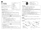
CGY750 Control Box
Dust Cover
Adjustment Screwdriver
Gyro Sensor
Mounting Pads
R6203SB Receiver
12
CONTENTS
Revolution Sensor
Magnets (2)
Sensor Mounting Bracket
Extension Cord:
13
SPECIFICATIONS
:LGWK&RQWUROOHU "PJB##Q
*\URVHQVRU ,CPJ ##Q
5HYROXWLRQVHQVRU ,,P+$##Q
/HQJWK&RQWUROOHU +P""##Q
*\URVHQVRU ,CPJ ##Q
5HYROXWLRQVHQVRU ,-P -##Q
+HLJKW&RQWUROOHU ,"+P J##Q
*\URVHQVRU ,PC$##Q
5HYROXWLRQVHQVRU ,BP ,##Q
:HLJKW&RQWUROOHU ,"$BIP 'Q
*\URVHQVRU ,JCJIPC'Q
5HYROXWLRQVHQVRU , " IP"'Q
2SHUDWLQJ9ROWDJH CK
C"K0R
&XUUHQW'UDLQ +,#
6HOHFWDEOH6HUYR)UDPH +,/IHJC,/I$-,/I
)%
&HQWHU3XOVH:LGWK $J,S+,/ITJC,/I
+-,O$-,/I
3UHVHWV 0H
H"$,$$,H
-,,+,,+$,N
*RYHUQRU5HVROXWLRQ , /I-#
7'.
530$FFXUDF\ U
+HDG6SHHG5DQJH H,,,H,,,#
2SHUDWLQJ7HPSHUDWXUH "V
V
,V
N"$V
&RQWURO6\VWHP 0'
%
%
6HQVRU .7%
#(%
#.7.)
/%%==
$QJXODU9HORFLW\5DQJH W HJ,,0'
)
R<( ' %
' (: % % (
)*+$,%:=
(
HH
%
H :
( ( %
#
%%
D%=
'
(%
'%
14
RECOMMENDED SERVOS
6L]H+HOLFRSWHUV5XGGHU6HUYR
Futaba S9254 Digital Servo Heli: FUTM0224
(280Hz/1520μS)
Futaba BLS254 Brushless Heli Servo: FUTM0524
(280Hz/1520μS)
Futaba S9257 EP Heli Digital Servo: FUTM0667
(280Hz/1520μS)
Futaba BLS257 EP Brushless Heli Servo: FUTM0527
(280Hz/1520μS)
&UTABA3$IGITAL(I3PEEDFUTM0226
(Z3
Futaba BLS251 Brushless Heli Servo: FUTM0521
(Z3
REPLACEMENT & OPTIONAL ITEMS
Futaba PC Interface CIU-2: FUTM0951
Extension 200 mm:
%XTENSIONMM
Extension 55 mm:
Extension 80 mm:
%XTENSIONMM
Mounting Pad:
1x22x22 mm (10)
15
CONNECTING THE CGY750
OLED Display
s$ISPLAYS MENUS PARAMEters and status information.
(1)
(2)
(3)
Edit Keys
s5SEDWHENSETTINGDATA
s5SE THE INCLUDED PLASTIC ADjustment screwdriver to press
the buttons.
R<( '# (: ( D
: ( )*+$, HH
R=
('%#
=
D% :( ' ( P)N</Q
# ( ( (
% '% %
(</;7J
(
)*+$,
(#
( (
% ( (% ( ( )*
</;7J
R( ( :( # /"FF
#H ( </ #% (' J %
( H (
'=
(D
16
(4)
(5)
(6)
(7)
(8)
CONNECTING THE CGY750
(1) Gyro Sensor:
s#ONNECTTHEGYROSENSOR
*Insert the sensor connector until it is
firmly locked.
(2) Rsen (Revolution sensor):
s#ONNECTTHESPEEDSENSOR
(3) S.Bus:
s#ONNECT TO THE 3"53 OUTPUT OF THE
receiver with the supplied extension.
(4) AIL Output:
s#ONNECTTHEAILERONSERVO
(5) ELE Output:
s#ONNECTTHEELEVATORSERVO
(6) PIT Output:
s#ONNECTTHEPITCHSERVO
(7) TH Output:
s#ONNECTTHETHROTTLESERVO
s#ONNECTTHE%3#W"%#ANDSETTHE
OPERATIONMODETO'YRO4(2MODE
(7) E2 2nd ELE Output:
s#ONNECTTHESECONDELEVATORSERVO
(Swash mode: H4-00 or H4-45)
(8) RUD Output:
s#ONNECTTHERUDDERSERVO
17
CONNECTING THE CGY750
Connection to the receiver, servos and sensors
<()*+$,L6(
( - ,C6H -J,C6 ( -J,6 (
% . 6 %
D%
%
' ( % F
( 6
=# ( 6 . ()*+$,6
%%
D
H'%
H:
(
(
%
:
(:%=
:
(;'%
(D
(
%' ( % GP%QH 7G7
P7%
QH < P
(QH 0 P<% Q =
'
(/"FF:(%
</;7JP7%
JQ
(
()*+$,
0
# ( D
%
% ( )*+$, % DF .
( ( )*+$, % DF ( (%
#('D
D'%=(
=#<()*+$,':%%D
%%%
' : #
H :' =F
#% ( (%
H (> % #
%H ( % F
.> (
:
DD''
#
%D!D
:((##'
(:
S.Bus channel setting
( 6 % '% : #
%% (% =#
( )*+$,
' ( (% #D 18
CONNECTING THE CGY750
('( - =
( %H (H
%%
H 'H % 'H % 'H #H ' ;
==:
(
()*+$,
%DF<(=%
)*+$,6(%'#
(%:>
% :
( %% D #
H = F
D%# % = ( 6
= ( #% ;= ( (%
#D=(=
= #
== '(
(% %% = ( =
D% ( )*+$, :
(
(
)K&;&==H%)7%)(%
(
(=
((%#D
PA/Q:
(
()*+$,6#
D%
(=
(
'%
()*+$,#
( ( )K &;&== (% H
(';==
%(%D
(
P
>:
(Q=
( ( #
% 7% ) (%
( ' # A&;
K ' % D ( G ; 7G7 6 # D
'
(0
N;>:(
(=
%
Using the CGY750 with a electric helicopter
 DANGER
It is necessary to remove the pinion gear
from the electric motor or disconnect the motor from the ESC before powering the model
19
CONNECTING THE CGY750
up for setup or bench testing. Electric motors
are extremely powerful and the capable of delivering the power instantly causing injury to
yourself, others, or the surroundings.
= ( )*+$, D' %% %
(%
# :
'
(7
(P</;7JQ
(
%;%
J
=
()*+$,6='
(#
#
('=#
(%
#
(#
=#
(7D=:
' ( #% ( !
# & ( #%
( D : '
( ' #
=
P)*&N</Q<(
(
)*+$,
'
(
%
<(
)*+$,:%%#%
(
(
%'%=#
( ('( ( </;7J (
)*+$,
&7
()*+$,
#
#%
%% #
<K;7;7K;7<7
##
(7
:
( ( ' # =# ( #
('(D
%
20
MECHANICS PREPARATIONS
WARNING
Newer high end servos and other radio
equipment are capable of placing large demands on the power systems in use today.
When using a regulator you must ensure that
the regulator is capable of delivering the current demands of the equipment you have selected. In addition to this make sure the wiring
and switch you have selected are capable of
handling high current draws.
s4HESERVOCURRENTDRAWCANBEUPTOHIGHER
on a flybarless helicopter. Always ensure your
receiver battery is fully charged before each
flight.
Even though the CGY750 is a high performance gyro and governor it will be necessary
to ensure that the helicopter mechanics are
also in optimum operating condition. Please
use the guidelines below and address all issues before installing and flying the CGY750.
s4HE#'9MUSTBEUSEDWITHARIGIDTAILROTOR
DRIVE SYSTEM !NY MODERN TORQUE TUBE OR BELT
DRIVE SYSTEM SHOULD BE ADEQUATE $O NOT ATtempt to fly the CGY750 using a wire driven tail
rotor system.
s !LWAYS ENSURE THE DRIVE GEARS TORQUE TUBE
pulleys, belt, bearings and shafts are in proper
working condition. If any of these items are
damaged or worn they must be replaced.
s The linkage rod, tail rotor bell crank, pitch slider
and tail rotor grips must operate without friction
to obtain the best performance from the CGY750.
Binding in the tail rotor control linkage will de-
21
MECHANICS PREPARATIONS
crease the performance of the CGY750 gyro and
this may also shorten the servo lifespan. Please
take the time now to ensure the tail rotor system
on your helicopter is working correctly, without friction or binding.
s6IBRATIONWILLAFFECTTHE#'9SOVERALLPERFORmance. All rotating components on the helicopter should be balanced to minimize vibrations in
flight. Ensure that your motor is running smooth
and all vibrations have been addressed before
installing and test flying the CGY750.
Gyro sensor replacement:
s %ACH #'9 GYRO CONTROL BOX IS CALIBRATED
specifically for the gyro sensor included. Do not
attempt to use another CGY750 sensor with the
control box as performance will suffer due to
being out of calibration. The calibration process
must be completed by an authorized service
center.
If your sensor needs replacement, please send
THE COMPLETE UNIT TO YOUR REGIONS SUPPORT CENter for repair.
22
OPENING SCREEN
K= (
%% = ( D
: ( )*+$,H : %
= (%
' %
#
=
%#
(':==
= ( ( =
# ( (%
( D
: # ( # %>'
#'' ( : (
#
%%: %%I < (
(M'(
D
%%:
( (%
# %% :(% ( )*+$,
%I
<(%:%%!
(:
(0#D=
)*+$,
(#:K
=
()*+$,(:
(:%%
('
(:#
=(%
=#' M <( (
(
%I
>'%
((%
#
#=
%
%%
(
%%
# ( ' = (
F
23
HOME SCREEN
& ( %I
( D #
%
(/#:%%D%
(
%N
%
:%%#%
#
L>
=
()*+$,
(P)N</Q#
= ( /"FF :( %
( D %
(
(':%%DD%
(
:%%%>%>D%:
<(%:%%
%
('((:
(
GH7G7
0'
Initial Home screen
1. Axis indication
2. Gyro operation mode
3. Gyro gain
4. on/off switch
7. Setting Menus
5. Yaw rate comp.
6. Battery voltage
(b) Aileron gain
display
(c) Elevator gain
display
(d) Gyro only
mode
1. Axis indicator Gyro
<(:%%%
:(:
(F
GH7G70
(
'%
2. Gyro operation mode Gyro
<(
(PQ=KPAQ=A#%
' # = ( PQ (: %
(
(
%==
%'
(
(%D#%
##
%
24
HOME SCREEN
RUD AVCS Mode
at 100% gain
RUD NOR Mode
at 100% gain
Neutral offset at
AVCS mode
('
(K
'#
(:%%
:( ( % > % =
( ' D=
>==#
(
%
>
=%%F
%=
T'(
T:
:
%%:
(
%
>
:
(
= # ( = (
F :%%
F#%=#
(
%
>=%%%=
H
=%% '(
H =%% %=
H =%% '(
%%: #
D>
:
(
(
(%:%%
('
(:PQ
(
%
:%%
Return servo to
center position
( ' (K ' # = #
(' ( D # F ( ( % #
D ##I D (
)*+$, < ( #% (' ( '
# : :
( = F#% A#%
XK XA#% XK
(%:%%
('
PRRRRRRRRQ
(
(
>
(D##I
(:
%
Read and memorize
the current neutral
position.
25
HOME SCREEN
3. Gyro gain Gyro
<(
(
''=
(F
(F
4. Operating condition Governor
<(
:(
(
('
'P&AQ
P&Q
5. Yaw rate comp. Governor
<( (
( ) : = =:
=
D%
6. Battery voltage
<( ( D
%
' <( % :%%
(' (: PG& 6<Q ( %
' (
=%% D%: ( 6
=% = %
' '
6
7. Setting Menus
(' ( D
:%% F
( #% '
#
(
'##
RPM display
Governor
<(D
%
'%
#
%%('
('.%
('
'H D
%
' % 26
HOME SCREEN
('(
'<(.%
D ( ( ( ( ' '
(
'
(%
%
#
'=
('F
#
Home screen options
( ( (# (: ( # PNQ
PQ>D
%
(D
#%
('(
(=%%:'
#Y6
%
'H.F
.H 7' #H &G70 % H
&
'.H%%
#F##%H
7%
#F##%
1. Maximum RPM
Governor
# ( (# ( # PNQ D
(: #F## . P.#Q
<(P.#Q%#
%%
D
'
(
PNQPQ>=
%
<(=
%%:
(>='
'M'(
2. Engine runtime
Governor
#
((#
(#PNQ>
:
(:
('
#%<(
#(:
(: %' ( ' ( D ' <( #%
# ( % #
##<
(
##%
(
PNQ
27
HOME SCREEN
PQ>=#
(
(
#:%%
D>
,
3. OLED display options [default: Saver]
( ( PQ %
( % :%%
#=
-,=
&D
()*+$,
%%DF
(&G70:%%
:
( D> =%% D'(
<( PQ (%
:F
(%==
(
%(
(PG'(
Q
%
(%
:%%#
=%%D'(
%%
#
4. Operation mode [default: Gyro+Gov]
<(%
(
'#=
()*+$,
WARNING
If the operating mode has been changed
then the CGY750 must be reset by powering
down and then powering back up.
P)N)Q6
(
('
('
%
P)N</Q <( ' % ( '
D% <( (
% (% =# (
('(
(P</;7JQ
(
)*+$,
P)N/"Q .
D %
:( P/" FFQ :(
%
%
<( D% ( '
28
HOME SCREEN
(
%
(P</;7JQ
(
)*+$, : ( Z7%
[ P7JQ 1. Roll rate maximum display
Gyro
0% ( #F## %% '
M'(
<(%
D>
,:(
()*+$,
:
1. Elevator rate maximum display
Gyro
0% ( #F## %
' =%'(
<( % D> , :( (
)*+$,:
WARNING Display
Governor warning display
Governor
<( :' #D% % :( ( '
' : ##
%
:
( (
( ( ' D% ( #D% :%% ( (
29
WARNING DISPLAY
:' #D% (: ( ' :%% D
D% % ( ( D ==
<( ' #
D :
( ( '
==
Sensor error
Gyro
WARNING
The helicopter must remain perfectly still
during the initialization process or a [SensorER] sensor calibration error may occur.
=:
'
%I
H:
( )*+$, : %
= -, K=
(
('%%
( )*+$, : ( )*+$,
' %%: ( (%
# %%
%
(
%I
(D#%
= ( D%# % ' (% ( =#
D = ( D'' = (
#%
Low battery
WARNING
The [Low Batt] warning is displayed if the
30
WARNING DISPLAY
receiver battery voltage falls below the [BAT/
FS] voltage set within the CGY750 ´ Governor ´ Expert menu. If this condition lasts for
more than one second then the Battery Fail
Safe function activates and the throttle servo
is brought back to idle. This is done to warn
you that the battery capacity is dangerously
low and you must land immediately.
( ( (
% D D
D'' ( #
% > %% ( :
D>
%
(
(
(
%
%:%%
=
,
(6
%
==
:%%
'L'
(=
Memory writing indicator
WARNING
Do not power off the CGY750 when the
Memory writing symbol is displayed.
( ' (' :
( ( )*+$,
(:%#
D:
##
(
Z.# :
' [ % '
(<(#
>
:
( : #
D :
( == ' (
= ( : :
( == ' ( :
'
(%%=
(
'#D%
31
SETTING MENUS
WARNING
Always exit the Setting Menu and return
to the home screen before flying your model.
The gyro operation is disabled within several of the settings menus to help with setup
tasks.
Always check the operation of the CGY750,
verify that the controls are operating the
correct direction and ensure the gyros are
correcting in the proper direction for all axis
before attempting to fly the model.
<( PNQ PQ > '
('( ( ' .Y P0)QH PG
)QH P7G7)QH P/
QH P)QR
P6Q6#&
(#
(:%
(#PNQPQ>
(:
(F
'
#
%
<(F
#
F
D
' (%' ( # PNQ PQ > = < F
( # #% '
D>
(6
'.=
(=
= F#%H PG) 6Q % ( # PNQ PQ > % ( (#
(:
%
(
'.'#=#
%
%
'=
(/#H67F
#
R<( P)Q ' # % = (
&
'.(D
P)N<(Q=
(
:(%
(D
(/"FF
32
SETTING MENUS
Push MODE +/– key
Push DATA
+/– key
Maximum RPM
Engine runtime
OLED Setting
Home
screen
Operating mode
Maximum Roll Rate
Maximum elevator rate
(Basic)
(Expert)
Gyro (RUD)
Gyro (AIL)
Gyro (ELE)
Swash
Governor
Push MODE +/– key
for 1 second
33
RUDDER GYRO BASIC SETTING
<( P0)Q6 # %% = (
=
()*+$,
%'
=
%=%%:
(
=
%
E
(Z/7K&A<GG<&A
A07<[
%
(#%
%%
(
# %% = ( # % % %>' =# (
D% #'%%
%'#
%D
% ( ( D :
( (
)*+$,:
(
#%%:
(
)*+$,
%I
A'
(P0)Q6#
=%%: J P0)Q6
X<
<#% % ( # (
(% ( %>' ( %
D%% %%: P0)Q6 X
)*0
(% %'(
% (%' ( % %>'
( #H # ( #
\
% > ( '(
(
( % ( % # ( =
#
\
=
(
%
(%
(
()*+$,
(%#
=
( :%% %: # ( ' %' %%
(#H'
(
(
%
D%% %>' =
% % (
34
RUDDER GYRO BASIC SETTING
% ( %%: " P0
)Q X G#
( %
= ( H ' D' %% ( # : % (
%>' ( % D%% ( #
6= ' = (
%% = ' (> = D'
('(
( ' = #
#
Push MODE
+/– key
(1) Start display
Use the mode [+] / [-] keys to
navigate the setting menus.
(2) Servo type [default: DG:1520]
Select the appropriate setting for the tail rotor
servo that you are using. Use the data [+] or [-]
key to choose from the following servo types:
$'$'OR!NALOG
DG 760: BLS251, S9256, S9251
DG 1520: BLS254, BLS257, S9254, S9257
35
RUDDER GYRO BASIC SETTING
WARNING
2EAD YOUR SERVO INSTRUCTION SHEET TO DETERmine the proper servo settings. The servo type
parameter within the CGY750 must match the
type of servo you are using. Incorrect setting
may damage the CGY750 or the servo. Incorrect setting may also result in a loss of control
during flight.
(3) Gyro direction [default: Normal]
This parameter controls which direction the
CGH750 (yaw axis) will compensate when the
helicopter rotates. Hold the tail rotor linkage
over the linkage ball on the servo, pick the helicopter up by the main shaft and rotate the mechanics counter-clockwise. The CGY750 should
compensate by adding clockwise rotation pitch
to the tail rotor blades. If the CGY750 compensates by adding counter-clockwise rotation pitch
to the tail rotor blades, then it will be necessary
to reverse the Compensation Direction setting
by pressing the [+] or [-] data key.
WARNING
Verify that the tail gyro compensates in the
correct direction before flight. If the compensation direction is incorrect the model will pirouette uncontrollably, at a very high rate.
36
RUDDER GYRO BASIC SETTING
(4) Limit setting [default: 100%, setting
range: 50~150%]
When the CGY750 is in the Sv.Limit parameter the gyro will no longer operate and the tail
servo will always center when the tail rotor stick
is released.
Always exit setup functions before attempting to fly the model. Before each flight
always ensure that the gyros are operating
and compensating in the correct direction.
The Servo Limit parameter within the CGY750
is used to set the mechanical limits for the tail
rotor servo. To obtain the best performance it
is recommended to set the limit in the CGY750
TO FOR BOTH DIRECTIONS AND THEN ADJUST
the servo arm length to set the mechanical
endpoints. After that has been completed use
the servo limit parameter to make small adjustments that could not be made mechanically.
6ALUESBETWEENANDARECONSIDERED
optimal.
.AVIGATE TO THE ;25$'YRO="ASIC´ Sv.Limit
menu and slowly move the rudder stick to the
left or to the right maximum extent and use the
data [+] or [-] key to increase or decrease the
maximum throw respectively. Ensure that the
pitch slider does not reach the maximum extent
and cause binding.
WARNING
When using the CGY750 for the first time,
or when making mechanical changes involving
throw, you must check and set the servo limits
again to prevent binding.
37
RUDDER GYRO BASIC SETTING
(5) Flight mode [default: 3D]
Selects the flight mode. Always try the “Sports”
flight mode first and if you determine that the
feel is not aggressive enough or if the pirouette
RATE IS NOT FAST ENOUGH THEN TRY THE h$v mIGHT
mode. The “Sports” Flight Mode will satisfy most
pilots.
The flight mode is changed by pushing the data
[+] or [–] key.
0IROUETTE2ATE
Sports
= 540 degrees per second
$
DEGREESPERSECOND
38
AILERON GYRO BASIC SETTING
<( PG)Q X 6 # %% =
(=
()*+$,%%
F=
Push MODE
+/– key
(1) Start display
Use the mode [+] / [-] keys to
navigate the setting menus.
(2) Gyro direction [default: Normal]
This parameter controls which direction the
CGY750 (roll axis) will compensate when the
helicopter rolls. Pick the helicopter up and roll
the helicopter to the right. The CGY750 should
compensate by adding left cyclic to the swash
plate. If the CGY750 compensates in the wrong
direction, then it will be necessary to reverse
the Compensation Direction setting by pressing
the [+] or [-] data key once.
WARNING
Verify that the CGY750 compensates in the
correct direction before flight. If the compensation direction is incorrect the model will roll
uncontrollably, at a very high rate.
39
AILERON GYRO BASIC SETTING
(3) Gyro gain [default:100%, ranges:0~120%]
The top line shows the Aileron Gyro Base Gain
and the bottom line shows the actual working
gain as set within the transmitter. If the Aileron
Gain Channel is set to [INH] within the CGY750
[S.Bus]->Basic setting menu, then the remote
transmitter gain adjustment is not available and
the actual working gain is set by using data [+]
or [-] keys within this parameter.
(4) Gyro working mode [default: CMT]
The available choices are CMT, Normal or
AVCS. The CMT mode will allow you to select
either AVCS or Normal mode by using the Aileron Gain Channel. The Normal mode will always
OPERATE IN .ORMAL 2ATE -ODE AND !6#3 WILL
always operate in AVCS Mode. Use the data [+]
or [-] key to select the desired working mode.
40
ELEVATOR GYRO BASIC SETTING
<(P7G7)QX6#
%%=
(
=
( )*+$, (
F=
Push MODE
+/– key
(1) Start display
Use the mode [+] / [-] keys to
navigate the setting menus.
(2) Gyro direction [default: Normal]
This parameter controls which direction the
CGY750 (pitch axis) will compensate when the
helicopter pitches forward or backward. Pick the
helicopter up and rotate the nose of the helicopter downward. The CGY750 should compensate
by adding aft cyclic to the swash plate. If the
CGY750 compensates in the wrong direction,
then it will be necessary to reverse the Elevator
Compensation Direction setting by pressing the
[+] or [-] data key once.
WARNING
Verify that the CGY750 compensates in the
correct direction before flight. If the compensation direction is incorrect the model will flip
uncontrollably, at a very high rate.
41
ELEVATOR GYRO BASIC SETTING
(3) Gyro gain [default:100%, ranges:0~120%]
The top line shows the Elevator Gyro Base Gain
and the bottom line shows the actual working
gain as set within the transmitter. If the elevator
Gain Channel is set to [INH] within the CGY750
[S.Bus]->Basic setting menu, then the remote
transmitter gain adjustment is not available and
the actual working gain is set by using data [+]
or [-] keys within this setting menu.
(4) Gyro working mode [default: CMT]
Selects the gyro working mode. The available
options are CMT, Normal or AVCS. The CMT
mode will allow you to select either AVCS or
Normal mode by using the gyro gain channel.
The Normal mode will always operate in Normal
2ATE -ODE AND !6#3 WILL ALWAYS OPERATE IN
AVCS Mode. Use the data [+] or [-] key to select
the desired working mode.
42
SWASH BASIC SETTING
<(P/
QX6#
%%=
(
=
(:(%
%%:(%
#F'=
Push MODE
+/– key
(1) Start display
Use the mode [+] / [-] keys to
navigate the setting menus.
(Confirmation screen)
(2) Swash type [default: H3-120]
4HE AVAILABLE OPTIONS ARE ;(= ;(=
;(=;(=;(=AND;3TANDARD=0USHing the Data [+] key once will show the next
SWASH PLATE TYPE AND A hv IS SHOWN REQUESTing confirmation of the change. If the Data [+]
(Set) key is pressed again within one second,
the new swash plate type is selected and the
“?” confirmation will disappear. If no confirmation is made within one second, the display will
revert back to the prior swash plate type and no
change will be made.
WARNING
All of the swash plate parameters are reset
when the swash plate type is changed. Please
proceed through the entire setup process before attempting to fly the model.
43
SWASH BASIC SETTING
(3) Servo type [default: Analog]
Select the appropriate setting for the cyclic servos. Use the data [+] or [-] key to choose from
the following servo types: DG1520 or Analog.
WARNING
2EAD YOUR SERVO INSTRUCTION SHEET TO DETERmine the proper servo settings. The servo type
parameter within the CGY750 must match the
type of servo you are using. Incorrect setting
may damage the CGY750 or the servo. Incorrect setting may also result in a loss of control
during flight.
(4) Helicopter Presets [default: 600-700]
Please select the most appropriate setting for
your model. The available presets are 450-550,
ANDORLARGER
The size profiles change many of the options
within the CGY750 to tailor the gyro towards a
certain helicopter size and the way that it reacts
in flight. When using this option the CGY750
will be adjusted to provide a consistent feel for
various helicopter sizes.
* Please refer to the back of this manual for a complete
listing of the helicopter profiles and the flight mode
presets.
44
SWASH BASIC SETTING
(5) Flight mode presets [default: 3]
The flight mode presets are used to control the
overall feel and aggressiveness of the CGY750
in flight. The adjustment range is 1 through
5. Flight mode 1 is the least aggressive and is
intended for beginners, sport, scale and even
SOME &# PILOTS &LIGHT MODE IS CONSIDERED
AVERAGE AND IS GOOD FOR INTERMEDIATE AND $
pilots who are not very aggressive. Flight mode
5 is intended for advanced pilots who like an
aggressive feel. This is a personal preference
option and it is recommended to test fly using
flight mode 2 initially.
Available Flight Mode Presets:
1 - Least aggressive, good for beginners
THROUGH&#PILOTS
!VERAGESPORTAND$mIGHT
)NTERMEDIATESPORTAND$mIGHT
4 - Fairly aggressive
5 - Extremely aggressive
45
SWASH BASIC SETTING
(6) Aileron servo reverse [default: Normal]
This setting is used to set the operational direction for the Aileron CCPM servo. The easiest
way to set up the CGY750 is to observe which
direction each servo needs to move when the
collective stick is moved towards positive collective pitch. If the servo is moving the wrong
direction then press the data [+] or [-] key to
reverse that specific servo within the GY750.
Once the collective is operating in the correct
direction, check the cyclic controls. If the cyclic
controls operate in the wrong direction, reverse
THE 3WASH !&2 FOR THAT FUNCTION WITHIN THE
CGY750.
(7) Elevator servo reverse [default: Normal]
This setting is used to set the operational direction for the Elevator CCPM servo. The easiest
way to set up the CGY750 is to observe which
direction each servo needs to move when the
collective stick is moved towards positive collective pitch. If the servo is moving the wrong
direction, then press the data [+] or [-] key to
reverse that specific servo within the GY750.
Once the collective is operating in the correct
direction check the cyclic controls. If the cyclic
controls operate in the wrong direction, reverse
THE 3WASH !&2 FOR THAT FUNCTION WITHIN THE
CGY750.
46
SWASH BASIC SETTING
(8) Pitch servo reverse [default: Normal]
This setting is used to set the operational direction for the Pitch CCPM servo. The easiest way
to set up the CGY750 is to observe which direction each servo needs to move when the collective stick is moved towards positive collective
pitch. If the servo is moving the wrong direction,
then press the data [+] or [-] key to reverse that
specific servo within the GY750. Once the collective is operating in the correct direction check
the cyclic controls. I the cyclic controls operate
INTHEWRONGDIRECTIONREVERSETHE3WASH!&2
for that function within the CGY750.
(9) 2nd Elevator reverse [default: Normal]
This setting is used to set the operational direction for the 2nd Elevator CCPM servo (only
used for the H4-xx Swash plate types). The
easiest way to set up the CGY750 is to observe
which direction each servo needs to move when
the collective stick is moved towards positive
collective pitch. If the servo is moving the wrong
direction, then press the data [+] or [-] key to
reverse that specific servo within the GY750.
Once the collective is operating in the correct
direction, check the cyclic controls. If the cyclic
controls operate in the wrong direction, reverse
THE 3WASH !&2 FOR THAT FUNCTION WITHIN THE
CGY750.
* This function is only used with the H4 swash plate
types. Otherwise the function is disabled.
47
SWASH BASIC SETTING
(10) Servo neutral adjustment
[default: 0μS]
TIndividual neutral adjustment
for each of the swash plate servos. All servo arms should be
perfectly perpendicular to the
control linkage with the collective
stick positioned at 0 degrees collective (usually centered). The
ELE2 neutral adjustment only
works if the H4-xx swash plate
type has been selected.
To use this function select the
servo you would like to adjust
and press the data [+] or [-] key
to position the servo as desired.
(11) Swash AFR (rate adjustment) [default: 50%]
4HE3WASH!&2SETTINGSAREUSEDTOADJUSTTHE
direction and amount of throw allowed for each
function. Think of this as the maximum travel
endpoint for each function, except you want
to set this to the maximum amount of cyclic/
collective pitch you would like available to the
CGY750. Use the Data [+] or [-] key to make
an adjustment.
If any of the functions operate the incorrect di-
48
SWASH BASIC SETTING
rection, then reverse the sign of the value. For
EXAMPLEWOULDHAVETOBECOME!LLOF
the servo, neutral and reversing adjustments
should be made within the CGY750 and the
transmitter functions should be left at the default
values.
4HE;!),2ATE=AND;%,%2ATE=FUNCTIONSAREDEpendent on servo arm length and head geometry, so it will be necessary to use a pitch gauge
to make adjustments. For the cyclic controls it
is recommended to start with 8 degrees of pitch
change in any one direction. Adjustments to
this value can be made after the 1st test flight
once you determine the cyclic rates and the
overall gyro behavior.
4HE;0)42ATE=ISTHEAMOUNTOFCOLLECTIVEPITCH
travel allowed and this value will be similar to
what you normally fly other helicopters with. A
GOOD STARTING RANGE FOR 3PORT $ AND &C IS
+/-10 to +/-12 degrees. Beginners may want to
CHANGE THE NEGATIVE COLLECTIVE PITCH TO DEgrees instead of -10.
(12) Swash ring [default: 100%]
This function is used to prevent binding of the
swash plate servos when the transmitter control
stick is moved toward a corner (for example,
full right and full aft cyclic). The default setting
IS 4HIS IS CONSIDERED NORMAL FOR MOST
helicopters. In some cases you may have to decrease the value to prevent binding. Press the
Data [+] or [-] key to adjust the value.
49
GYRO SENSOR INSTALLATION
<( ' (% D #
'
%
=#H %
- P $J##Q : =# A
7'
#
('
(#(=
=
((%
D
#
(
( #
' ( '
%=
(%
#=
\
=###
'%
<
!
( ' H ' (
( =
%'#
:
(
((%
(
%%
(F<(D%=#
('
#
F
: ( =
( = (
(%
( ( ( F #
%'#
:%%%==#
#
(
('%'
%
& (' %
%' (
( % D ('H'(#
('
((%
'=
(%'
('%
()*+$,
%
DF %' ( % ( ' K=
(
(
!#%%>%
s%LEVATOR0ITCHAXIS
s2UDDER9AWAXIS
s!ILERON2OLL
axis
Gyro Sensor
50
GYRO SENSOR INSTALLATION
Important: The CGY750 gyro sensor must be
mounted so that the roll and pitch sensing axis
are in alignment with the helicopter. Any misalignments over 1/2 of a degree will cause a loss in
performance. Please take extra care in this step
to ensure the optimum flight performance.
s4HE BOTTOM OF THE #'9 'YRO
Sensor must be perpendicular to
the main shaft.
s4HE ROLL AXIS MUST BE PARALLEL TO
the tail boom and the pitch axis
must be perpendicular to the side
frame.
TROUBLESHOOTING
If any issues are noted during flight (such as
drifting, inconsistent hold or inconsistent control
rates) then please review the following troubleshooting recommendations.
1. Always verify that the tail rotor and swash plate
mechanisms operate, and that the drive system
51
GYRO SENSOR INSTALLATION
is in proper working order.
2. Electromagnetic interference could be causing the problem. If you feel everything is set
up correctly and that the helicopter is vibration
free, then consider moving the gyro sensor to a
new location away from servos, ESC and drive
motors.
6IBRATIONSWILLDECREASETHEPERFORMANCEOFALL
gyro systems. Even though the CGY750 gyro
sensor is the most vibration resistant gyro sensor available, eliminating vibrations will always
improve performance. Throughout extensive
testing it has been found that the CGY750
gyro sensor performs best when the sensor is
mounted rigidly to the airframe. This is mainly
DUETOTHESENSINGOFALLAXIS)TISHIGHLYRECommended to avoid using soft foam pads as
this may allow the gyro to bounce around on
the roll and pitch axis, causing instabilities and
possible loss of control during flight.
All components of the helicopter must be balanced and operate in a smooth manner. The
newer gyro sensors are so sensitive (and
extremely accurate) that even something as
simple as a bad ball bearing can cause enough
vibration to cause the sensor to read incorrectly. Main and tail rotor blades must also be
perfectly balanced. Ensure that your engine is
running smoothly and properly tuned. If you
feel that all of the criteria has been met, then it
is recommended to relocate the gyro sensor to
a different position on the helicopter and test fly
again to look for improvements.
52
SWASH SERVO INSTALLATION AND SETUP
<( )*+$, - ==
:( %
(:D%:
H3-140
H3-120
PIT
PIT
AIL
AIL
ELE
ELE
H3-90
PIT
H4-00
ELE
AIL
PIT
AIL
ELE
ELE2
H4-45
ELE
Normal
AIL
PIT
PIT
ELE2
AIL
ELE
FRONT
Swash Servo installation
0
# :(( = ( :( %
(: #
( (%
%% (
:( %
( '# (%
\
#%
*
#
(%D
(=%
' ( :( %
%
53
SWASH SERVO INSTALLATION AND SETUP
:
(
(
#
(%D
A#%
/ '%#%%.#F
' (% :
( ( )*+$,
( #
=
(% D
<( F =
% D :
( ( #
D
('
%
(.#F'(%D
(%D
()*+$,
#
H<K0;:(=
,,U %% = %% D
#
(%D
,
: #
(%
%%: ( )*+$, %I (
)*+$, P/
Q X < =
%
(:(%
(
#
(
(%
A'
( < #
( )*+$, %
( (
#
( #=
\ #
#
=
(D
H%
(
%' #'' (
(>:
(\#=
#
(
A'
( P/
Q%A< ' ( #<( :%% D% ( '
( % # (
= ' %
#
( :%% D #
( ' : ( #
=#
(7&
(
( #
% : (
# D%H #% %% #
(%:%#
(%
%
> : %%
54
SWASH SERVO INSTALLATION AND SETUP
= (
( #' ( %%
(=
#'
(:'
H
(
P/
Q=
('
(
& ( ' ( = ( %%
% '
H
(F
%:%
# ( %%
> ( = :
( #
\ 0% =
= D% <( :%% D
(,%%
=
<#% %% ( # (
% (
( =
% %% #%% ?
#
D
# ' ( P/
Q6 XG;
7G7;&GA
?
#
= ( =
.
( %>' D%% (
# (%
\ #% %% ( :
(
. ( =: ; =
% > =:
=
(
(:(%
%
=:
= ( :( %
%
( :' H
( :%% D ( '
=
(P/
Q7G7
#
=
F#%N$,:%D#$,.
(
%=
;'(
%
>
('(
=
(
( :( %
%
( '(
= (
:(%
%
%=
H
(
('=
(P/
QG
#
!% (>H = (
( :( %
# ( >
##
= ( %%H ( %%
55
SWASH SERVO INSTALLATION AND SETUP
=
A'
( P/
Q X 6 X
G
#
<(:%%D%
('
( # ' ' ( ''H (
(:(%
=
%%%
(
( # D% , ' (
:( ( %%
> .>
#(% ?
#
(,'=
(D
(#
D%
( # D% :
( ( (
''
(
%':
(
(
%D#
%=%%'(
%
(
#
#(:#(
(
(D%
%%
D
:
(C'=
%?
(%=
(P/
QX
6 X%
#
% C '
=%(
(#
D%
(
%
(
%D#%=%%=
%?
(P/
QX6X
7%
#
% C ' = %
(
=
(%=
(%
#
(H
D<(=
%#%
'%% (% :%% D %:
(
(7%
' ( ( ''H ?
( %%
' = (%
\
#%
%%=
(H<K0;=
(%
%%
=
:
( ( 56
SWASH SERVO INSTALLATION AND SETUP
(%D
,,U
(
(D
#%
HD
('#
D=
#
'
M
(#%
(> ( % %%
##
=
=
%
=
(:(%
?
#
%
:
(
(D>=
(#%(
'#'
%:
(
((%\
D#
#
#(% ' M: #
> :
(
(
:%%
D
#
(D=M'(
57
AILERON/ELEVATOR GYRO SETUP
Finishing the setup:
Using the T8FG, T12FG, T12Z and 14MZ Remote Gain Functions (roll, pitch and yaw)
# D #
F%
' =
= %H %
:
% = #
\ #% ' ( )*H )*G )*7G7 (% :
( ( #
(
()*+$,P6QX6#H
' ( P)AQH P7)AQ P)AQ (
(%
J<( ' =
:
( #
(% %
%% ( ' (%?
#
D#=#:
(
(=
<('=
%%D'
:
(
=='
?
D%
% = #
\
#%==
(
%
%%
(G7G7'(%D
$,
(
'#(%D
PA&Q&
(
#(D#
%
H ( =%'(
# (% D ('
PKQ
WARNING
Verify that the gyro compensates in the correct direction for all three axis before flight. If
the compensation direction is incorrect, the
model will roll, flip, or pirouette uncontrollably at
a very high rate.
58
AILERON/ELEVATOR GYRO SETUP
Setting the CGY750 gains by using endpoints
or manual adjustments
= #
( #
' ?
#
%% D% : (% ( #
#> ( ?
#
' : (% = (
( (% ' D :
( %
:
( ( #
( P66Q
X)AP66QX7)A(%
(
(%
(
?
#
:
( #
= (
(% #> ( ' ?
#
(=
:
(
(
#
(#PK;A&Q
:
(
( #
# % D (
==
' D =%'(
#
% = #
\ #%==
(
%
J
%%
(G7G7'(%D
$,
(
'#(%D
PA&Q&
(
#(D#
%
H ( =%'(
# (% D ('
PKQ
WARNING
Verify that the gyro compensates in the correct direction for all three axis before flight. If
the compensation direction is incorrect, the
model will roll, flip, or pirouette uncontrollably at
a very high rate.
59
AILERON/ELEVATOR GYRO SETUP
Manual gain adjustment
=
%(%=
= #
F
% ' ?
#
H ( D% ?
('#%%:
(
()*+$,
D
( ( P6Q6 X)A P6Q6X7)A
PA/Q<('
?
#
:#D
'
(PG;
7G7Q6X)'
(
PNQ
PQ>
J<( ' ?
#
# D '
( PG ; 7G7Q6]) '
(
PNQPQ>
%%
(G7G7'(%D
$,
(
'#(%D
PA&Q&
(
#(D#
%
H ( =%'(
# (% D ('
PKQ
WARNING
Verify that the gyro compensates in the correct direction for all three axis before flight. If
the compensation direction is incorrect, the
model will roll, flip, or pirouette uncontrollably at
a very high rate.
60
TAIL ROTOR SERVO INSTALLATION AND SETUP
Following your transmitter instructions, program your transmitter as follows:
7D% ( ' =
:
( (
#
('#
K)*:
(
(
#
(#
''
C,UK
(
#
= ( A#% /% =%'(
$,UK=%%%
Z
' <( )[ %
(#%=#
%
(<%
<K;7
,,U=D
(
%=
'(
0;
+$U=D
(%=
'(
<(
:%% ( #F## .> ?
#
( % (
%
M'(
(D#%
##
(
,U=
'F
(
%
(%
WARNING
Do not connect the tail rotor servo to the gyro
until the servo type has been selected. Operating
the servo using the incorrect setting may damage
the CGY750 or the servo.
&
(
#%
H
(
:%%:
('
%I%%:
( :
( ( ZRudder Gyro Basic
Setting[
=
(#%%
(
< (
#
( ( ( (
::
(=:
61
TAIL ROTOR SERVO INSTALLATION AND SETUP
%%
(
%
(#(
( ( ' #
( # : =# ( <
( : %%: ( ' %I7
(ZRudder Gyro Basic Setting[ # ' #
" Z
G#
'[(%
(%#
#
(:%%#
90°
%
#
(
(
%
(
%
((:#
(
=
(#
%%
(
%D%%%:
((
%
(#%'%
#% : #% : #
# %' ( D%% $## =# &
(
%D%%(D
%%%
(#D>
('
(
%
(
%
(
%%
(#:
13.5mm
62
TAIL ROTOR SERVO INSTALLATION AND SETUP
%%: ( :
( ( ZP0
)Q6 X KG#
[ (%#
=
(
%
/%
(
%
%>'
(%>'D%%
#''
(&
(%#
%
(%>'
(%>'
D%% ( 'K # ( ##
(,V=
(:
(
(
%
%% = ( %D%
('
(
%:
(
D'
<
(:==
F
'#
#'#
(
(:
D>&
('(#%
%
I
# ( % > ( '(
(
#
=
(
'(
%>
: % ( (
%
D%=%=
%
(
( % D%H ( :%%
D
(
%
(%
(
#
> ( (%
D ( # (=
( #( %>:
=# ( <( ' (% #
D'%>:
(
(
%
D%=
('#
D
' %>: ( (
% D% ( :%% D ( Z) 0
[ ' :
(
( ' = ( ZGyro Basic Setting[
%
(#%
exclusively, then the rudder gyro setup is now
complete.
63
BEFORE FLIGHT CHECKLIST
%: = (
( #
D
=%%('
(> ( ' #
' (
' .> (
'!#%#
((%
K=
(
(':'(#%>
%%:%=
(#=#
:
(
#
%%:
('
%I
(>=
(
(
#
%=
(
%
%
K= (
%% = ( # : %%
7
(
(%
%
D:(#
(=%%F
=
(
(:
K=
(
('
'
(
# PK A#%Q (
( '
%
<
%%
%=
(
(#
(
K= (
( ' #
( = %% ( F D= M'(
=
(#
(
#% :%% %%H MH %
%D%H
('(
64
ADJUSTMENTS DURING THE TEST FLIGHT
WARNING
Always level the swash plate using the cyclic
stick before applying throttle and spooling the
main rotor blades up. During takeoff small corrections may be necessary. If you make large
corrections while the helicopter is on the ground,
it may tip over since the helicopter is firmly on the
ground and the gyros are overcompensating due
to the lack of movement.
Some helicopters may have a tendency to
resonate/shake during spool up. Always leave
the helicopter on the ground until this resonance
or shaking goes away. If this issue continues, it
is recommended to try some rubber skid stops
or take off from a softer surface such as grass.
Vibrations contribute to this ground resonance.
Verify that everything on your model is balanced
correctly.
* When the CGY750 is used with a ESC or
BEC and a power switch is not used there is a
possibility that the intermittent connection as
you connect the flight battery may cause the
CGY750 initialization to fail. Always ensure that
the gyro has initialize properly by verifying that
the gyros are compensating as the helicopter
is moved. It is recommended to use a power
switch on the power supply line to avoid this
possibility.
#M'(
(%D=#:
:(#>'
('
(#(%
?
#
((%
K=
(
(G7G7'
65
ADJUSTMENTS DURING THE TEST FLIGHT
$,U ' ( A#% ' #
<> ( #% == ( (
#
#
D
#
(#%'
M'(
J& ( #% ## H % (
#% (
( ' == . (
' ' :
( =# A#% K
# # .> (
%
=D
(%%
##I
R = ' ' :
( ( =%'(
#
:
(H=#
(
#M'(
%
(#%
(
('==('
()*+$,
'#
KA:
()*+$,==
D><(
%
=D
(%
%
:%%D##I
R.% )?
#
E =# ( # M'(
%
(#%(
('==('
( )*+$, ' # K A: ()*+$,==D><(
%
=D
(%%
:%%D##I
=
(
#M'(
H('
('
' # K =% ( #%
' ( ' ( % %
' % %%
H
(
('%'(
%
R = %> = ( (% = ' ' '
(
#
H?
(''
(
)*+$,
Rudder gyro adjustments:
<(<%
0;=
:
(
(
#
?
(
=
((%
F#%
,,U0;H:
(
('
#H
((%
:%%
66
ADJUSTMENTS DURING THE TEST FLIGHT
( "$, '; :
( (
>
F
=:%%>
(#%
=
H
(
(0;
=:%%>
(#%
%:H
(
(0;
<( ' (% D % ( % D'
%%
L>%%%%<%'&
(
(D(H
('D
%=
M
(#%'
(> ( ' = ( =%'(
#
<%%
(':%%D%:=
(%
%JM'(
#
(('(
(<('=
(/%
%D('(
(
(M'(
#
(
(%:
('D
##I
<( % H % ( ' % D% %'
( % %' ('
##
%
=#<('%
%% =# #% #% ( F
% (% % (
%
=
('\=#/:
(
' ' M'(
( % =
67
RECOMMENDED GYRO GAIN SETTINGS
Recommended gain settings:
Size
450-550
750-more
2ECOMMENDED'YRO'AIN
AIL/ELE Gyro
25$'YRO
68
USING NORMAL MODE
.
%
'K . =
?
' H ## (
K . F%% =# ( A#%.%
(
=# D=
=K # ( '
K # %% ##' = ( % #
%%(%D
('=(%
A#% . ( %% ##' #F'
#
D
D
= :%% D ' ( A#% . % =
.
(=:('
(
:%% D <( % (% D
,'=
%
(
L:(
(
%
(
%>: ' # D% ( #
,'='(
%
(:%%D
L
(
:%%
D
(
%
#
%
#F'=
=
#
(%
L%
#
#% = # =#
(:
(
= :
( D
: A#% .
K . =%'(
H #
( (
' % ( =
#>
' # (' :
( ( #
<
##I ( : #% =%
( ' :
( ( #
( #
D : A # % . K . A#%tKtA#%tK :
( <( :%% H ' (
(
:
(D##I
69
GOVERNOR BASIC SETTING
<( ( '\ =#
% =
<( # (9) Servo limit point setting #
D
!
Push MODE
+/– key
(1) Start display
The editing menus are scrolled
by pushing the mode + or – key.
(2) Revolution setting [range: 1000 ~ 3000
rpm]
Setting the main rotor revolution. This is calculated by engine revolution with the gear ratio of
the main shaft.
!"#
.>
(%('
HJHD#
'
(:
(
(.
(
D('
(
N^>
$
#
&'*+
=%
' #F' ( < "._ < J) =
%D
( =
H (
.
'D
=
(
70
GOVERNOR BASIC SETTING
(3) Gear ratio [default: 8.00, range: 1 ~ 30]
Input the main rotor gear ratio by pushing the
data + or-key.
Notes:
s)F THE GEAR RATIO IS NOT PROPERLY SET THE SET
speed and actual engine speed will be different.
s4HE GEAR RATIO SHOULD BE GIVEN IN THE HELIcopter instruction manual. If the helicopter instruction manual does not give the gear ratio,
calculate the gear ratio as follows:
Engine
pinion gear
N2
Rotor
main gear
N1
)
`A ;AJ
s#ARRY VALUES LESS THAN TO THE NEXT
whole number.
71
GOVERNOR BASIC SETTING
(4) Servo selection [default: Analog]
Select the throttle servo type. Digital servos offer the best response. The type is changed by
pushing data + or – key.
WARNING
This parameter must match the type of servo you are using. Incorrect setting may damage
the CGY750 or the servo, possibly resulting in
a loss of control during flight.
(5) Stick switch [default: 30%]
The governor can be activated by throttle
stick position. Move the throttle stick to the
on position and push SET key, the on point is
MEMORIZED7HENYOUPUSHTHE23%4KEYTHE
function is inhibited. When the governor on/off
switch is inhibited, the stick switch is automatically turned on.
When governor is turned on and off by transmitter throttle stick
<( (
( ' D
== :
( ( #
(
%
><(=%%:'D
(
72
GOVERNOR BASIC SETTING
(Governor operating point)
Set speed
Set point or more and
60% of set speed
s4 H R O T T L E S T I C K H E L D A T T H E S E T P O I N T O R
more´´´2EMAINS/.
s4HROTTLESTICKLOWEREDPASTTHESETPOINTORLESS
than the slow side´´´OFF
100%
set point or less
(OFF region)
0%
(OFF at slow side)
73
GOVERNOR BASIC SETTING
(6) Governor on/off switch [default: Inhibit]
It selects the governor activate switch if additional switch is used. Pushing the SET (Data+)
key activates the function. The on/off direction
is changed by pushing the SET key again. The
FUNCTIONISINHIBITEDBYPUSHINGTHE23%4$ATA
key.
When governor turned on and off by switch
' ( :
( ( &A ( ' <( =%%:' D ( Governor can be turned
on and off by a switch.
s3WITCHSETTOONPOSITIONANDENGINERUNNINGAT
ORMOREOFSETSPEED´´´ON
s4 H R O T T L E S T I C K S E T T O M A X I M U M S L O W
position´´´2EMAINS/.
s3WITCHSETTOOFFPOSITION´´´OFF
74
GOVERNOR BASIC SETTING
(7) Battery failsafe setting [default: Inhibit]
The governor goes into the failsafe mode when
the battery voltage is below BFS.Volt. When
activated, the governor is deactivated and the
throttle servo is moved to B/FS position. Move
the throttle stick to idle position. The B/FS
CONDITIONISDEACTIVATEDFORSECONDSANDRETURNEDTO"&3AFTERSECONDSHAVEPASSED
Move the throttle stick to B/FS position as desired. Push set key to confirm the setting. PushING23%4WILLINHIBITTHEFUNCTION
(8) Yaw rate compensation [default: CW/
TOP]
This works the revolution compensation during pirouette. Set the mode to match the gyro
installing direction, either CW/TOP, CW/BOTM,
CCW/TOP, CCW/BOTM by pushing the Set key.
0USHINGTHE23%4KEYINHIBITSTHEFUNCTION
At the governor only mode, this function is inhibited.
CW: clockwise
CCW: counter clockwise
TOP: normal side
BOTM: reverse side
75
GOVERNOR BASIC SETTING
(9) Servo limit point setting
It sets the throttle servo maximum throw. It is
fundamental for governor operation. It must be
set prior to other function setting. It must be set
when the throttle linkage is changed or trim is
changed as well.
For this setting, idling position is set first, then
high position guided by the display. Push the
data + or – key to memorize. “*Finish*” is displayed when the setting is completed. “Error”
is displayed when the setting position is out of
RANGETOONARROWFROMHIGHTOIDLEBELOW
through).
When using the CGY750 for the first time, or
when making changes in the throw of a servo,
always perform the limit setting operation.
(10) Limit point testing
It tests the limit point if they are correct. Push
data + or – key. Throttle servo moves to setting
point followed to the display.
76
GOVERNOR BASIC SETTING
(11) Revolution sensor testing
It tests the output level of the revolution sensor.
Turn the engine by hand, and check the output
level. The display indicates the current level on
left side numbers, maximum level on right side
numbers. The output level needs to be more
THANFORCORRECTOPERATION
77
MOUNTING THE MAGNET AND SENSOR
.= ( %' = %% ( #'
(
(#'
(
'
(
(:D%:
Cooling fan
Magnet (Embedded in cooling fan.)
Sensor (Attached to engine flange
through a stay.)
(
%%'
(#'
(#=MH%=
(%#
'
Magnet operating side check
6' ( #'
( = ( (>
(
'
Sensor
Magnet
<(
(
:((
(%%
( Z%
'[
# :
( ( ZGovernor Basic Setting[
%
(#%
%%
(#'
:
(
(='
(.>
(
=
(#'
:
(=%
78
MOUNTING THE MAGNET AND SENSOR
;#
0%% (% ( = ( #'
#
' .> ( (% D
" ## #
$
+##
7#D ( #'
( (% ( :(( D
F ( (
, #
%'0
F
(
#
%
(a6%
Cement the magnet to the cooling
fan so that the magnet is level
with this side of the cooling fan.
Magnet
=
(%'=D%D
H
HD%
D#
'
(#'
(
=
(%'=
(
%
(
'%
Sensor mounting
<(#
'#
(
((%
'
.
(
(
<#
#D%
0%% (% ( = ( '
(
(
(
79
MOUNTING THE MAGNET AND SENSOR
D
: ( #'
D# J##
<'(
( '
(
:
(
('#
'M'
<##D%
%
( #
' #
( (
( (
( =#H ( = (
(%
<#% #
(%
(#'
#
'
%% ( ( '
(::(
<'(
(
'
(:
(
(
''
('#
:
Sensor adjustment
?
( D
=
%
-,U
(Z%
'[ # :
( ( ZGovernor
Basic Setting[
%
(#%
Sensor
Magnet
1-2mm
Center of sensor
is offset.
Sensor
case
2.2
mm
3.7mm 3.7mm
80
MOUNTING THE MAGNET AND SENSOR
<(
=
(==
=#
(
=
(D=%:(
#
'
(
= ( % % ( -,U :( (
#'
%D%:
(HD'
(
% ( #'
(
( -,U
#%<(#'
' F#
% J## = D
:( (
D'(
% ( #'
H (
#'
#(
('
#%
#D%=
(D%
'(
' ( : (
: #%
'(
(>
(
81
FUSELAGE SETTING PRECAUTIONS
Throttle servo linkage precautions
< ==
% ( 'H D ( =%
%:' :( ' ( %>'
.> ( ' ' : D% .> ( (: = ( #
7 <K =
=
%D%
,,U
%:
(
('
&?
(%
(
('#
(%
##
=
(
#
>
=
(
:((
(
=
(
' D% ==
( % #F
H ( ' #
#F##
%
Fuselage vibration countermeasures
= ( (%
=# :>H ( '
#
=# %% %H (
D
% ( ' :%% 7' D
:%% % D% ( ' =# #F## =
# <(=H #> (
( ' D
= (
( D
= '
% ' D ( ' 'D%#
Use of a tuned silencer
<( = % # ( ' (
% D D
%%
==
=# (
:
( #% #=M?
82
FUSELAGE SETTING PRECAUTIONS
(%%'
(
(
'
(' % ( (
% '
= ( ' (' %%H (
' :%% =# =
% :
( #=M
(
%%:
(D
D%
83
GOVERNOR OPERATION
Governor operation
<( )*+$, =# ,,, ,,,#
# /:H ( ' #
D
' ( <( )*+$, ==
(':(
('
'%'
R) E &
(
D%I ( '
(
Condition of the governor to be on
=
H ( ' :(
(
D%:
!
<( ;== :
( ==
':
<(
> :
( :( <(;==:
(
:(
'
&==
<('F
-,U=
(
'
<(:>'%
The following operations do not indicate trouble:
When engine speed rises above the set speed:
% # ( ' D
(
Throttle operation speed and ON/OFF point:
=
(
%
F-,U=
(
( ( %H ( &A;&
# # == :
( ( ' 0%
#
(
(:
('
(
#
(
(&A;&
84
GOVERNOR OPERATION
(('
Deviation from set speed:
<( )*+$, D%I ( ' :
(
W U=
(
F#%H=
(
.
$,,#H
(
.:%%
D
W $#/:H
(D%#=#
(
=
%
85
GOVERNOR SPEED SETTING
<( )*+$, D ' ( (% (
Z ,%
(%[#:
(
(ZS.BUS
Basic Setting[ ( ' ' (
% = # ( ' ' ;== :
(H ( Z- )
;==:
([=
:
(
(ZGovernor Basic
Setting[
%
(#%
Direct set by transmitter on Gov. mixing
('#F'
(< "._
< J)
:
(
(.=
(
( H ( ( D :
(
:
((
(:
(
R = ( ' #F'H = #
\#%
Using by 3position switch
(.
(:
(
(ZJ
%
'[ # :
( ( ZGovernor Basic Setting[ % (
#%
Speed setting precautions
s7HENTHESPEEDSETTINGCHANNELTRAVEL%0!!46
!&2ISSETTOORLESSPOINTSANDCANNOT
be set.
s4HE ENGINE MAXIMUM SPEED RANGE LIMITS THE
maximum speed setting.
s4EST FLY THE HELICOPTER WITH THE GOVERNOR TURNED
OFF AND TACH THE MAIN ROTOR 20- WHILE IN HORIZONALmIGHT4HISISTHEMAXIMUM20-THATCAN
be achieved with the engine and pitch setup that
you are using. Please set the governor maximum
SPEEDTOAPPROXIMATELY20-SLESSTHANMAX
86
GOVERNOR SPEED SETTING
20-%XAMPLE)F20-SISMAXTHENSET
governor to 1750)
s4HEMAXIMUMSPEEDCANBEVERIlEDATTHE-!8
speed display. However, this could show some
unlocked main rotor condition which is not accurate.
Speed
Reference
<(
#
7=
%D
('
(
'
F
<(#
=
(('
%
(==D
:
(
( J F#%H = ,,# J $,,#H ( #
7 ('=#J,
,,UH
(
:%%
(' =# "-, ,,# <( #
7=
(%
%==
(
J
'
Point 3
Point 2
Point 1
Speed setting
channel travel
Neutral
<( (' %% % '
HJH
87
S.BUS BASIC SETTING
6 %% C (% # D %#
D #
'% :H ' )*+$, =
( GH7G7&G
((%<((%
'#
=# :
( ( P6Q
6#
==
''
DH
(
#
D PA/Q F#%H = ()A 7)A #
' =
'' D
H
(
(#
PA/Q
()*+$,:%%
( %%: #> ' ?
#
:
(
(
#
WARNING
Always verify that the S.Bus function assignments match your transmitter function assignments. If any changes are made within the transmitter function assignments, then it will also be
necessary to make the changes within the S.Bus
function assignments as well.
Push MODE
+/– key
(1) S.Bus connection setting:
start display
Use the mode [+] or [-] keys to
navigate through the menu.
Setting ranges common: 1 ~ 16ch, DG1,
DG2, INH
88
S.BUS BASIC SETTING
(2) S.Bus setting: Aileron
channel [default: 1ch]
Using the data [+] or [-] keys to
set the correct channel number.
(3) S.Bus setting: Elevator
channel [default: 2ch]
Using the data [+] or [-] keys to
set the correct channel number.
(4) S.Bus setting: Throttle
channel [default: 3ch]
Using the data [+] or [-] keys to
set the correct channel number.
(5) S.Bus setting: Rudder
channel [default: 4ch]
Using the data [+] or [-] keys to
set the correct channel number.
(6) S.Bus setting: Pitch channel [default: 6ch]
Using the data [+] or [-] keys to
set the correct channel number.
(7) S.Bus setting: AIL gain
channel [default: 9ch]
Using the data [+] or [-] keys to
set the correct channel number.
89
S.BUS BASIC SETTING
(8) S.Bus setting: ELE gain
channel [default: 10ch]
Using the data [+] or [-] keys to
set the correct channel number.
(9) S.Bus setting: RUD gain
channel [default: 5ch]
Using the data [+] or [-] keys to
set the correct channel number.
(10) S.Bus setting: RPM channel [default: 7ch]
Using the data [+] or [-] keys to
set the correct channel number.
<==>*?
&@*J
channel [default: 8ch]
Using the data [+] or [-] keys to
set the correct channel number.
(12) S.Bus data reset
This resets the S.Bus channel assignments
back to the defaults. Press the data [+] key and
[Exec ??] will be displayed as a confirmation.
Press data [+] to confirm the reset back to the
default settings.
90
RUDDER GYRO EXPERT SETTING
<(F
#
'=%
%>
'
(
(D%
D
=#=#
('<
(F
#'
(6#H(%
(#PNQ>
=
(#:%%('=#
(
6 7F
< F
( F
# (%
(#PNQ>=
(
D#:%%D%
(1) Start display
(#PNQ#PQ>
'
(
#
(2) Rudder servo neutral setting
default: 0 uS
ranges: -140 ~ +140 uS
<(#
(
%
=
(
(
PNQPQ>
#>?
#
(3) Gyro basic gain
default: 100 %
ranges: 50 ~ 120 %
<( #
( D ' = ( '
<(D
?
('U=
% #
' #
( ( ' ()*+$,
%
91
RUDDER GYRO EXPERT SETTING
(4) Rudder exponential
default: -60% (Sports-AVCS), -40% (Sports-Normal), -20%
(3D-AVCS), -20% (3D-Normal)
ranges: -100% ~ +100%
<(#
(=%=
(
%
% 0' ( #D :%%
%
=
=% ' ( #D
:%% %
# '' =% ?
= <( 0 7b =
:
(
#
%D
#>
(?
#
(5) Rudder delay mode
default: Function
%
P
Q = =
% =% P
Q=%''=%
(6) Control delay In
default: Sports=12, 3D=15
ranges: 0 ~ 20
<( #
( % # (
>=#
%
:%=
'(
G'%
:%%%
#
(=%
(
PNQ
PQ>
?
(%
92
RUDDER GYRO EXPERT SETTING
(7) Control delay Out
default: Sports=10, 3D=12
ranges: 0 ~ 20
<(#
(%:(
(
>
D>
(
%
G'%
%
#
(=%
(
PNQPQ
>
?
(%
(8) Stop delay
default: 120%
ranges: 100% ~ 400%
<( #
?
( ''
=
(
G'%:%%%
(
%
%
'%D
(
PNQ
PQ>
?
(%
(9) Gyro working mode
default: CMT
<(#
('
'#<(
(.<HA#%K<(.<
=
:(
:
(D
:
( A#% K # D ( '
%
(
PNQPQ>
%
(
'#
93
RUDDER GYRO EXPERT SETTING
(10) Pirouette speed
default: 450 deg/sec (Sports), 720 deg/sec (3D)
ranges: 100 ~ 999 deg/sec
<(?
(
=
(<(
=%
% "$, '; #
+J,';0#:( ,,
U <( D
# = ( % (: ( % =
(
(
PNQPQ
>
?
(%
(11) Gain change up delay
default: 12
ranges: 1 ~ 50
<( ( % = ( ' ' =# %: ('(<(%
=#%
(
' ' ( % # % (
'
=
>'%
(
PNQPQ>
?
(%
(12) Gain change down delay
default: 3
ranges: 1 ~ 50
<(
(%=
(''=#('(
%: <( % =# (' %
0'
(%#
%(
'=
>' % (' % (
PNQPQ>
?
(%
94
RUDDER GYRO EXPERT SETTING
(13) Rudder histeresis
default: 7 uS
ranges: 0 ~ 50 uS
<(?
(
>%%'
(
PNQPQ>
?
(%
(14) Gain tracking
default: 0 %
ranges: -20% ~ +20%
<( ?
( ' (%' =%' ' %=
'(
(
PNQPQ>
?
(%
(15) F/F mixing
default: off
<( %
( ; : #F' (% ( ' D ' (
#F'D=
('#
#
#
('=#
;#F'(%:
(
()*+$,0
#
%
%
#F'
:
(
#
(:%%
%%?
(
'%
('
95
RUDDER GYRO EXPERT SETTING
(16) F/F mixing rate
default: 0 %
range: -100% ~ +100%
<(#
?
(;#F'
<(PGQ
%:P/Q('(
?
D%%%
G' % :%% # #F' ( %
%
#:=#
:N
(
(17) F/F mixing acceleration gain
default: 0 %
range: 0 ~ 200 %
= ( %%
> # L>%H (
( %
' ( ;
#F' (% #
= ( ('
(
PNQPQ>
#>
?
#
(
PNQPQ>
?
(
%
(18) Sensor mode
default: Moderate
<( #
%
( = (
' '% <( .
X.%Xc>H D
( D%
.
(%
:%% =# ( D
:( ' ( .
' #%% (%
#=#D
(c>.%
' ( PNQ PQ > ?
(
96
RUDDER GYRO EXPERT SETTING
%
(19) Neutral compensation
default: ON
<(=
:>
%%
(
%
=
( = #' % #
< ( =
==
%H ( ( (%
= D
H ##I (
% = ' 0 (%
H ( =
# :> :%% ( L> ''##
(>
(=
=
:>
%
(
PNQPQ>
D%D%
(
(20) Yaw smoother
default: ON
%
(
%=%'(&H
% D# # F
( &==H % %
( %=%'
(
PNQPQ
>
D%D%
(=
(21) Stop boosting
default: Off
range: Off ~ 200%
<(=
:>=D
'
(''
# % #
( PNQ PQ
97
RUDDER GYRO EXPERT SETTING
>
?
(%
(22) Gyro data reset
<(
%%=
('#
D>
(=%
%
(
PNQ>
P7F ddQ (: !#
( PNQ > ' =# ( %%=
('#
:%%D
98
AILERON GYRO EXPERT SETTING
<(F
#
'=%
%>
'
(
(D%
D
=#=#
('<
(F
#'
(6#H(%
(#PNQ>
=
(#:%%('=#
(
6 7F
< F
( F
# (%
(#PNQ>=
(
D#:%%D%
(1) Start display
(#PNQPQ>
'
('(
(#
(2) Exponential
default: -40% (FLT.Mode-3, 600-700)
ranges: -10% ~ +100%
<(#
(=%=
(G%
% 0' ( #D :%%
%
=
=% ' ( #D
:%% %
# '' =% ?
= <(G 7b =
:
(
#
%D
#>
(?
#
(3) Control delay in
99
AILERON GYRO EXPERT SETTING
default: 7 (FLT.Mode-3, 600-700)
ranges: 0 ~ 20
<( #
( % # (
>=#
%
:%=
'(
G'%
:%%%
#
(=%
(
PNQ
PQ>
?
(%
(4) Control delay out
default: 7 (FLT.Mode-3, 600-700)
ranges: 0 ~ 20
<(#
(%:(
(
>
D>
(
%
G'%
%
#
(=%
(
PNQPQ
>
?
(%
(5) Stop delay
default: 120%
ranges: 100% ~ 400%
<( #
?
( ''
= ( G' % :%% % (
%
'%D
(
PNQPQ
>
?
(%
<K>!
default: 98% (FLT.Mode-3, 600-700)
ranges: 0 ~ 150%
<(#
(K#'=
'
(%H
((%':H
100
AILERON GYRO EXPERT SETTING
D
(
%=%'#DM
(7) Control feeling
default: 5n
ranges: 1 ~ 10n
<(#
(
%=%'=
(%
%'
(%H
(
%=%
' :%% D 0' ( %H (
%=%':%%D#
(8) Rate Constant
default: 50% (FLT.Mode-3, 600-700)
ranges: 0 ~ 150%
<(#
%
(
=
(%%
?
( %% D
: '(
M'(
==
(9) Roll rate setting
default: 100%
ranges: 50 ~ 150%
<(#
?
(%%D
(%
%
(%
#
(
(%%
=
((%
(10) D gain setting
101
AILERON GYRO EXPERT SETTING
default: 200% (HeliSize=600-700)
ranges: 0 ~ 250%
<( #
?
( 0 ' ==
%
' = ( % ' (' ( (
= ( % =%' #
%
(=%
(11) Sensor mode
default: Middle
<( %
( = ( ' ' % < ( D .
X.%Xc>H D
( D%
%
('#
('=
((%
('
N^>H
(#('
(12) Data reset
<(
%%=
(%'#
D>
(=%
%
(
PNQ>
P7F ddQ (: !#
( PNQ > ' =# ( %%=
('#
:%%D
102
ELEVATOR GYRO EXPERT SETTING
<(F
#
'=%
%>
'
(
(D%
D
=#=#
('<
(F
#'
(6#H(%
(#PNQ>
=
(#:%%('=#
(
6 7F
< F
( F
# (%
(#PNQ>=
(
D#:%%D%
(1) Start display
(#PNQ#PQ>
'
(
#
(2) Exponential
default: -40% (FLT.Mode-3, 600-700)
ranges: -100% ~ +100%
<( #
( =% = ( 7G7 %
% 0' ( #D
:%%%
=
=%'
(#
D %% %
# '' =% ?
=<(7G77b=
:
(
#
%D
#>
(?
#
(3) Control delay in
default: 10 (FLT.Mode-3, 600-700)
ranges: 0 ~ 20
103
ELEVATOR GYRO EXPERT SETTING
<( #
( % # (
> =# % : =: =
%
G'%:%%%
#
(=%
(
PNQPQ>
?
(%
(4) Control delay out
default: 10 (FLT.Mode-3, 600-700)
ranges: 0 ~ 20
<(#
(%:(
(
>
D>
(
%
G'%
%
#
(=%
(
PNQPQ
>
?
(%
(5) Stop delay
default: 120%
ranges: 100% ~ 400%
<( #
?
( ''
=
(
G'%:%%%
(
%
' % D ( PNQ PQ
>
?
(%
<K>!
default: 98 % (FLT.Mode-3, 600-700)
ranges: 0 ~ 150 %
<( (K #' =
'
(%H
((%':HD
(
%=%'#DM
104
ELEVATOR GYRO EXPERT SETTING
(7) Control feeling
default: 5 n
ranges: 1 ~ 10n
<( #
( % =%' = ( %
% ' ( %H ( %
=%' :%% D 0' ( %H
(
%=%':%%D#
(8) Rate Constant
default: 50 % (FLT.Mode-3, 600-700)
ranges: 0 150%
<( #
%
( = (
%
?
(%
D
:
'(
M'(
==
(9) Roll rate setting
default: 100 %
ranges: 50 ~ 150 %
<( #
?
( ( D ( %
%
(%
#
(
(%%
=
((%
(10) D gain setting
default: 200% (HeliSize=600-700)
ranges: 0~250%
<( #
?
( 0 ' ==
%
105
ELEVATOR GYRO EXPERT SETTING
'=
(%
'
('
((
= ( % =%' #
%
(=%
(11) Sensor mode
default: Middle
<( %
( = ( ' ' % < ( D .
X.%Xc>H D
( D%
%
('#
('=
((%
('
N^>H
(#('
(12) Data reset
<(
%%=
('#
D>
(=%
%
(
PNQ>
P7F ddQ (: !#
( PNQ > ' =# ( %%=
('#
:%%D
106
SWASH EXPERT SETTING
<(F
#
'=%
%>
'
(
(D%
D
=#=#
('<
(F
#'
(6#H(%
(#PNQ>
=
(#:%%('=#
(
6 7F
< F
( F
# (%
(#PNQ>=
(
D#:%%D%
(1) Start display
(
PNQPQ>
'
('(
(#
<Q>VXZ+
default: 100%
ranges: 30~150%
<(?
(
(
%#F'
<(
(:
D
(D?
%%
<>VX\Z\+
default: 100%
ranges: 30~150%
<(?
(
(
%
#F'
<(
(:
D
(D?
%%
107
SWASH EXPERT SETTING
<^>VX\Z\Q+
default; 100%
ranges: 30~150%
<(?
(
(
J%
#F'
<(
(:
D
(D?
%% % %D% /" :(
#
<_>ZXV+
default; 100%
ranges: 30~150%
<(?
(%
(#F'
<(
D ?
= %=
'(
%%
<K>ZX\Z\+
default; 100%
ranges: 30~150%
<( ?
( % %
#F' <( D ?
= %=
'(
%% % %D% = /""$
:(#
<`>ZX\Z\Q+
default; 100%
ranges: 30~150%
108
SWASH EXPERT SETTING
<( ?
( % J %
#F'
<( D ?
= %=
'(
%%
%%D%=/"
"$:(#
<q>\Z\XV+
default; 50%(H3-120), 100%(except H3-120)
ranges: 30~150%
<(?
(%
(#F'
<(
D ?
= : %%
<z>\Z\XZ+
default; 50%(H3-120), 100%(except H3-120)
ranges: 30~150%
<( ?
( %
% #F' <( D ?
= : %%
<={>\Z\X\Z\Q+
default; 100%
ranges: 30~150%
<( ?
( %
J %
#F'
<( D ?
= :
%%
%%D%=/"
:(#
109
SWASH EXPERT SETTING
(11) Linkage compensation aileron
default; 0%
ranges: 0~100%
<(?
(%>'#
=
(%
%M
(%
<( " 'H %=
'(
(('(%:
(12) Compensation direction of the aileron
default; plus
<(%
(
=
(%#
<(
('D('
(0
N ^ > ( = D
#%%
(13) Linkage compensation elevator
default; 0%
ranges: 0~100%
<( ?
( %>' #
= (
%
% =% ( %
<("
'H:
(('(%:
(14) Compensation direction of the elevator
default; plus
110
SWASH EXPERT SETTING
<(%
(
=
(%
#
<( (' D (' (
0
N^>
(
=
D#%%
(15) Speed compensation
default; 50%(H3-120), 0%(except H3-120)
ranges: 0~100%
<(#
?
(=
(
(
% ( %
?
#
(
(%D##%
(16) Swash rotation
default; 0 deg
ranges: -90~+90 deg
<(#
?
(
%(
'
(
PNQPQ>
#>?
#
(17) Pitch zero setting
default: 1520 uS
<( #
( ( I =
)*+$, . ( ( > ( I (
( N ^ > <( I ( '% ##I )*+$, <( % (: Ze[
#>
(
'
111
SWASH EXPERT SETTING
(18) Pitch low setting
default: 1940 uS
<( #
( ### ( =
)*+$,.
(
(
>
###
(
( N ^ > <( ### ( '%
##I
)*+$,<(%(:Ze[
#>
(
'
(19) Pitch high setting
default: 1100 uS
<(#
(#F##
(
=
)*+$,.
(
(
>
#F##
(
( N ^ > <( #F## ( '%
##I
)*+$,<(%(:Ze[
#>
(
'
(20) Data reset
<(
%%=
(:(%
#
D>
(=%
%
(
PNQ>
P7F ddQ (: !#
( PNQ > ' =# ( %%=
('#
:%%D
112
GOVERNOR EXPERT SETTING
<( ( % = ( ' =
=
( F
#% ( ( # N ^ >
=#
(
()6
# %H '
( ) 7F
# ( # N ^ > = # ( '
()7F
#
D
()6#
(1) Start display
(#N^>H
%%
('(
(
'#('#N^>=#
(
H D' D> ' D
#
(2) Governor working mode
default: Governor
<(%
(':>'#
(
'%
%#
#<()
#:>
('%
%
<( %
%#
G#
#%:>:(
('%
F
(
'%
'%
D %: (' N ^ > ( #
('( ( G#
# %
H
(#(6) Throttle data mode (%D
<F#
113
GOVERNOR EXPERT SETTING
(3) Revolution display mode
default: Rotor
<(%
(%
%#=
(
(#
'%
('
N
^>H
(#('
(4) Operation response
default: Middle
<( %
( ' %
(D
#
(='
(
'
N^>H
(#('#
# %
H .%] '%: 'H
.
] '% 'H c> ]6(%
#
(5) Governor gain
default: Moderate=30%,Middle=40%,Quick=60%
ranges: 10~100%
<( ( ' :>' ' ( (
('H
(''
#
%%('=%
<(D
'
(#
'(
D=
(%
:'''
> % (' N ^ >H ( % ('
114
GOVERNOR EXPERT SETTING
(6) Throttle data mode
default: Optimize
<( %
( (
% ('
N^>H
(#('
Optimize:
)*+$, ( (
% '% ##
A
(
(
%
'
(
#
Fixed:
<(!F
(
%
%I%
(
%
##=%
#
Tx.Curve:
)*+$,
(F
(
%
=#
(
#
<( (
% ' ( #
L(
(G#
#%
H
(
#(%D%
(7) Revolution change up delay
default: 8
range: 2 ~ 20
<( ( % = ( %
=# %:
('( (' N ^ >H ( % ('
(8) Revolution down delay
default: 10
range: 2 ~ 20
115
GOVERNOR EXPERT SETTING
<(
(%=
(%
=#('(
%:('
N^>H
(%('
(9) Start delay
default: 5
range: 2 ~ 20
<( ( % ' ( ' = (
' (' N ^ >H ( % ('
(10) Low limit at hovering
default: 25 %
range: 0 ~ 80 %
<( ( (
% %: %#
' ('
%
%D
('
N^>H
(%('
(11) Low limit at idle up
default: 45 %
ranges: 10 ~ 80 %
<( ( (
% %: %#
' % %
%D
('
N^>H
(%('
(12) Battery F/S voltage setting
116
GOVERNOR EXPERT SETTING
default: 3.8 v
ranges: 3.5 ~ 7.5 v
<( ( D
=% = %: D
%# %
' ( %
' D ( D
<(D
(
==
D ==
#=
% #> (
D
# = M'(
# $
, #
=
' ( D
%# <(
% (' D (' 0<N ^ >
''
'%
'=%%:
sCELLS.I#DOR.I-(.ORMALVV
sCELLS,I&E.ORMALV^V
sCELLS,I0O.ORMALV^V
(13) Governor data reset
<(
('#
=%
'<( Z7Fdd[ % D (' N ^ > = =#
(' N > ' #%
( H %
Z7F[
(
%('
#N ^ > ' !#
%H (
D
117
SWASH SETTING PARAMETER TABLE
<( D% (: ( #
D (
(% I =%'(
# #D
= (
:
(
(ZSwash Basic Setting[
=
(#%
450-550
P%'Q
Flight Mode
1
2
3
4
96%
97%
98%
98%
100%
Cnt.DlyIn
15
12
7
4
2
Cnt.Dlyout
15
12
7
4
2
-60%
-50%
-40%
-30%
-20%
AVCS.Dmp
EXP.
Rate.Cst
D.Gain
ANG. Base
5
20%
20%
20%
10%
0%
100%
100%
100%
100%
100%
360d/s 420d/s 420d/s 480d/s 480d/s
P7%
'Q
Flight Mode
1
AVCS.Dmp
Cnt.DlyIn
Cnt.Dlyout
EXP.
Rate.Cst
D.Gain
ANG. Base
2
3
4
5
97%
98%
98%
99%
100%
15
12
10
8
5
15
12
10
8
5
-60%
-50%
-40%
-30%
-20%
20%
20%
20%
10%
0%
100%
100%
100%
100%
100%
240d/s 300d/s 300d/s 360d/s 360d/s
118
SWASH SETTING PARAMETER TABLE
600-700
P%'Q
Flight Mode
1
2
3
4
96%
97%
98%
98%
100%
Cnt.DlyIn
15
12
7
4
2
Cnt.Dlyout
15
12
7
4
2
-60%
-50%
-40%
-30%
-20%
30%
40%
50%
40%
30%
200%
200%
200%
200%
200%
AVCS.Dmp
EXP.
Rate.Cst
D.Gain
ANG. Base
5
240d/s 270d/s 300d/s 300d/s 300d/s
P7%
'Q
Flight Mode
1
2
3
4
97%
98%
98%
99%
100%
Cnt.DlyIn
15
12
10
8
5
Cnt.Dlyout
15
12
10
8
5
-60%
-50%
-40%
-30%
-20%
30%
40%
50%
40%
30%
200%
200%
200%
200%
200%
AVCS.Dmp
EXP.
Rate.Cst
D.Gain
ANG. Base
5
180d/s 210d/s 240d/s 270d/s 270d/s
119
SWASH SETTING PARAMETER TABLE
750-More
P%'Q
Flight Mode
1
2
3
4
96%
97%
98%
98%
100%
Cnt.DlyIn
15
12
10
8
5
Cnt.Dlyout
15
12
10
8
5
-60%
-50%
-40%
-30%
-20%
30%
40%
80%
70%
60%
200%
200%
200%
200%
200%
AVCS.Dmp
EXP.
Rate.Cst
D.Gain
ANG. Base
5
210d/s 240d/s 270d/s 270d/s 270d/s
P7%
'Q
Flight Mode
1
2
3
4
97%
98%
98%
99%
100%
Cnt.DlyIn
15
12
10
8
5
Cnt.Dlyout
15
12
10
8
5
-60%
-50%
-40%
-30%
-20%
30%
40%
60%
70%
60%
200%
200%
200%
200%
200%
AVCS.Dmp
EXP.
Rate.Cst
D.Gain
ANG. Base
5
150d/s 180d/s 210d/s 240d/s 240d/s
120
LINKAGE COMPENSATION
<(F%(:
(%>'#
F#%=
(/ J,:(#
R<( %H %
( ##
(% D
#F##
('(D
(
#
3LWFK FDOLEUDWLRQ 7KLV VKRXOG EH VHW SULRU WR WKH
FRPSHQVDWLRQSURFHVV
<( ( ( ' (
)*+$,.
(
(
>
(I
&
(
_
(/
7F
#H(
(
D
<(
(I
##I
()*+$,
. ( ( > ### &
(
G:#H(
(
D
<( ### ( ##
I
. ( ( > #F## & ( /'( #H ( ( D
<(#F##
(
##
I
3LWFKPRYHPHQWFDOLEUDWLRQ
.> ( :( %
=%
:( (
( > =
?
( %'
( = ( %>' (
(
:(%
DM
. ( ( > #F## #>=
(:(%
M
D
?
'
(<XGH<X7G7#F'
( /
7F
# . (
( > ### .> (
#?
#
#F##
>
121
LINKAGE COMPENSATION
$LOHURQPRYHPHQWFDOLEUDWLRQ
.
(
(
>
.
( % > '(
%=
.> =
(
(%
?
(GX< #F' (
/
7F
# D ##I (
(% D ?
D
( %=
'(
. ( ( > #F## & ( G ( /
7F
# . ( % > %=
'(
?
( G (
/
7F
#
D##I
(
(%
(
= ( :(
( G H # D ( #
H (
0#
(
#
6
(%=
'(
%(%D?
. ( ( > ### ?
G # : (
#F##
(OHYDWRUPRYHPHQWFDOLEUDWLRQ
.
(
(
>
.
( %
> : .> (
( ( ( %
?
( 7G7X<H 7G7XG #F'
( /
7F
# D
##I
(
(%D?
D
(:
122
LINKAGE COMPENSATION
. ( ( > #F## & ( 7G7 ( /
7F
# . ( %
> :?
(7G7
(
/
7F
#
D##I
(
(%
(
= ( :(
( 7G7 H # D ( #
H (
70#
(
#
6
( : %
(% D ?
. ( ( > ###
?
7G7
#:
(#F##
& ( # ( /
7F
# . ( %
> : L>%?
( # D##I
(
(
(
<6&&<&A
(ENC "+$J-BCJH#%ENC "+$J-BC
,C,*D
>H(#H('H(DJBB"B$Ha
-.
©&54!"!#/20/2!4)/.
123