1
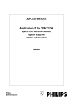
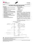
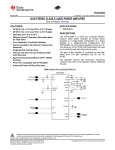
off grid inverter manual
catalogue
I Preface............................................................................................................................................................. 2
1.1 Summarize ................................................................................................................................................2
1.2 Notes.........................................................................................................................................................2
1.3 open box, storage and transit ....................................................................................................................2
1.3.1 open box ................................................................................................................................................2
1.3.2 storage....................................................................................................................................................2
1.3.3 transit .....................................................................................................................................................3
II Brief introduction........................................................................................................................................... 3
2.1 mostly technic parameter ..........................................................................................................................3
2.2 system working principle..........................................................................................................................4
III install and operation......................................................................................................................................... 4
3.1 prepare install ...........................................................................................................................................5
3.1.1 Load configuration guide:...................................................................................................................5
3.1.2
Recommended wiring of the main circuit...........................................................................................5
3.2 install ........................................................................................................................................................5
3.2.1 device aspect(picture3.1)..................................................................................................................5
3.2.2 The definition of the back panel terminals(picture3.2).....................................................................6
3.3 operation ...................................................................................................................................................6
3.3.1 the front panel and display module instruction......................................................................................6
3.3.2 LED display module and the button operating instruction ....................................................................6
3.3.3 Startup and shutdown.............................................................................................................................7
3.3.4 Display module display instruction .......................................................................................................7
Ⅳ
3.3.5 Notes......................................................................................................................................................9
Power protection and abnormal information processing .............................................................................. 9
4.1 Protection class and action status..............................................................................................................9
4.2 Power alarm and protection parameters................................................................................................10
4.3 Common symptoms and treatment .......................................................................................................10
4.4 Replace fan ...........................................................................................................................................11
V Appendix (communication Protocol) ............................................................................................................ 12
5.1 Service Guarantee .................................................................................................................................12
1
off grid inverter manual
I
Preface
1.1 Summarize
This product uses advanced sinusoidal pulse width modulation (SPWM) technology, the main circuit use
Mitsubishi IGBT modules, thick film circuit drive protection is Japanese Mitsubishi, high reliability, full
protection, waveform distortion, high power and so on.
The PV Series inverter DC input rated voltage DC48V/110V/220V; the output is AC 220V/60Hz. solar
energy is mainly used for new power generation system. It has all the advantages of inverter, can also
transport facilities, poor conditions in the mountains, pastures, islands and other areas without electricity,
provides absolute reliability for use new energy generation.
1.2 Notes
This user manual allows you to easily operate and maintain the system, be sure to take good care of it.
Before use of this product, please read these instructions carefully.
● Before use it,pls carefully read the instructions.
● To avoid injuring personal safety, the installation must be grounded.
● Don’t use high humidity or temperature, have gas or flammable volatile.
● when switch off within a short time, do not open the lid, so that the system's residual voltage
electrical shock or damage to the machine..
● Avoid overload to avoid inverter failure.
1.3 open box, storage and transit
1.3.1 open box
The series inverter through a rigorous inspection before shipment, but may be damaged in transit, so after
the first check box the following are complete, model specifications are consistent with the order.
☉ inverter complete body;
☉ user manual;
☉ warranty card;
☉ certificate;
☉ Products matching parts and other accessories of the order.
1.3.2 storage
The products should pay attention to the following to avoid possible adverse effects suffered in the store.
☉ placed no dust and dry air of the place;
☉ environment temperature -20 ℃ ~ 50 ℃;
☉ Relative humidity less than 90%, and no drops of water condensation;
2
off grid inverter manual
☉ away from corrosive gas and liquid.
☉ Power long-term need, regular half-day power over the power to prevent moisture inside the device.
1.3.3 transit
Process in the handling of this product should avoid strong vibration, Shuaidie, bump, is strictly prohibited
box upside down, not lost when moving out of the box accessories, manuals and warranty cards.
II
Brief introduction
2.1 mostly technic parameter
SF-INVI1-5
model
DC input
AC input
AC output
rated capacity(KVA)
5
input rated voltage (VDC)
48
input rated current(A)
123
input DC voltage range (VDC)
40-75V
allowed input voltage range (VAC)
220±15%
input rated current (A)
22.73
bypass convert time (ms)
≤5
output rated capacity (KVA)
5
output rated power (KW)
4.0
output rated voltage and frequency
220VAC,50HZ
output rated current(A)
22.73
output voltage precision(V)
220V±3%
output frequency precision(HZ)
50±0.05
Wave distortion rate(THD)
(line load)
≤3%
dynamic response (load0←→100%)
5%
power factor(PF)
0.8
overload ability
150%,10seconds
peak value coefficient (CF)
3:1
convert efficiency (80% Resistive load)
90%
display
LED display
low frequency transformer output
3
off grid inverter manual
2000
noise(1 M)
≤50dB
environment temperature
-10℃~+50℃
humidity
0~90%,no drew
altitude (m)
≤2000
working
environment
isolation intension(input and output)
demensi
on
protect
function
660*400*700
W、L、H (mm)
Protection for input connecting contrary, input lack of voltage, output overload, output short
circuit, over load
2.2 system working principle
The PV inverter with DC input, to provide DC power inverter, through the inverter supply wave of pure
energy for the load, when the PV input voltage or inverter failure, quickly switch to bypass power mode.
Specific principles are as follows:
DCi
np
ut
in
ve
rt
o
u
t
p
u
t
fi
l
t
e
d
ri
v
e
s
w
it
c
h
p
o
we
r
s
u
pp
l
y
i
s
ol
a
te
p
o
w
e
rs
u
p
p
l
y
i
s
o
l
a
t
i
o
n
d
is
p
la
y
m
od
u
ie
SPWM
s
te
e
ri
n
gc
ir
c
ui
t
A
Cbyp
as
sin
p
ut
b
yp
as
ssw
it
c
h
ci
rc
ui
t
ACo
ut
pu
t
III install and operation
The installation of the machine to pay attention to the rationality of the first, including the choice of
installation location, good ventilation, the load is properly configured, the appropriate choice of wire and
connected properly, so as to ensure the inverter can be safe and normal operation.
4
off grid inverter manual
3.1 prepare install
3.1.1 Load configuration guide:
There have rated current, voltage data on the equipment signs , power requirements can be obtained by
multiplying the two VA value. Some equipment in watts (W) label, the wattage can be obtained by multiplying
the approximate 125 VA (VA) number. Users must be carefully inspected when using load power, so as to avoid
overload. Equipment under normal operating state, in particular, the actual power in standby mode power than
the machine marked lower, to equipment users in the use of nominal power should be subject, taking into
account the impact of equipment in the starting current, best 30% power left margin to ensure reliable power
supply.
3.1.2
Recommended wiring of the main circuit
Here are the inverter power wires, cables, recommended cross-section, for reference, inverter voltage and
current reference according to the different sections of the BVR matching type 450/750V copper core PVC
insulated flexible cable.
(Recommended cable cross-sectional area in sheet 3.1)
sheet3.1
unit:mm2
5kVA
input DC wire
output AC wire
25
6
3.2 install
3.2.1 device aspect(picture3.1)
S
O
L
A
RO
F
FG
R
I
DI
N
V
E
R
T
E
R
picture
3.1
5
off grid inverter manual
3.2.2 The definition of the back panel terminals(picture3.2)
PE
DC INPUT
+
AC INPUT
-
L
N
AC OUTPUT
L
N
p
i
c
t
u
r
e
3.2
3.3 operation
3.3.1 the front panel and display module instruction
the display module unit shown in Figure 3.3
D
C
B
Y
P
AS
S
L
I
N
E
O
U
T
F
A
U
L
T
I
N
V
E
R
T
O
N
O
F
F
D
A
T
A
S
T
A
T
E
图F
igure3.3
3.3.2 LED display module and the button operating instruction
Main Power (LINE) indicator: bypass input instruction .light on mean the bypass input is normal.
Bypass (BYPASS) indicator: bypass output instructions, the output light on mean the bypass mode.
Inverter mode (INVERT) indicator: inverter output instructions, light on mean system can work properly
6
off grid inverter manual
Output (OUT) LED: inverter output instructions, light on mean inverter normal output
DC source (DC) LED: DC level indicator, the amount of light on mean the DC normal DC
Fault (FAULT) indicator: System Fault Indication
ON: Power button / mute button, press the power button for 2 seconds to boot.
OFF: OFF button, press the off button for 2 seconds to shutdown.
DATA: Data check button, press the button to see the machine continuous data.
STATE: status check button, continuously press the button to see the machine status information.
Reset button: When the machine failure (over current, overheating, overload, etc.), the inverter will stop. Press
this button to reset the machine to restart the inverter.
Mute button: Inverter failure alarm, press this button to cancel the alarm
3.3.3 Startup and shutdown
Disconnect all power before the ahead power , in case the terminals connected to the rated DC input, AC
input, AC output. To ensure that wiring is correct, connect the power, when the front panel LCD should light on
and the internal buzzer continuous alarm. If the LCD does not light or buzzer did not ring, check the DC input.
including startup, press the power button (ON) 2 seconds, the inverter start, stop the alarm buzzer, the
inverter working in the inverter (INVERT) mode.
when shutdown, press the off button (OFF) 2 seconds. Inverter stop, continuous buzzer alarm. If not, or
overhaul a long time, please disconnect the input and output open space.
Press the mute button to eliminate the buzzer alarm.
When the power inverter voltage is too high, too low voltage inverter, inverter over-current, inverter
overload, inverter overheating, then the exclusion of such failure, may be reset through the reset button to restart
the inverter
3.3.4 Display module display instruction
◆ Standby display interface
AC:
IN DC:
OUT VO:
IO:
0V
0Hz
0V
0V
OHz
0.00A
D
Shows the input DC voltage; output voltage, frequency and current values.
◆ Data check (DATA) display information (through s press this button continually to see the power of
real-time data):
7
off grid inverter manual
1 B
y
p
a
s
sv
o
l
t
0
.
0
V
F
r
e
q
u
e
n
c
y
0
H
z
2 I
n
v
e
r
t
v
o
l
t
0
.
0
V
F
r
e
q
u
e
n
c
y
0
H
z
3
4
InputDC
0.0V
Outpu
t
0.0V
Fr
equen
cy
0Hz
5
O
u
t
pu
tC
u
rr
e
n
t
0
.0
A 0
.
0%
◆ Status check (STATE) display information (through the continuous press this button to see the power of
real-time status information):
1 By
pas
sV
olt
age
R
egu
lar
2 I
nve
rtVo
lta
ge
Reg
ula
r
3 O
utWorkStyle
Invert
4
5 I
nv
e
r
ts
t
at
e
Re
g
u
l
ar
6 O
ut
pu
tM
ai
nb
us
R
eg
ul
ar
7 L
o
adS
t
a
t
e
R
e
g
ul
a
r
8
In
pu
tDC
R
eg
ul
ar
off grid inverter manual
3.3.5 Notes
▲ prohibited suddenly cut off at full load (or turn) all the load, because it easy to cause damage to the
machine, the correct way is by using the inverter power button off / boot, or load one by one off (or connect).
▲ chassis cooling fan is controlled by temperature, just getting machine or load is light does not turn the
fan is normal, only when the internal temperature control above 50 ℃ collection point will be started.
▲ with a motor load, please leave 3 to 5 times the power margin, with non-linear load (such as computer,
industrial computer) Do not exceed the display, the total nominal capacity of the host. That with these two loads,
the inverter derating required.
Ⅳ
Power protection and abnormal information processing
4.1 Protection class and action status
The type of UPS protection and the protection occurs, the power of the state in sheet4.1.
sheet4.1
Protection
Input
Description
备
reverse
注
Reversed polarity input DC voltage, inverter fault
protection
Automatic
Input
input DC voltage lower than the short voltage Points ,
reset, the
undervoltage
the inverter will automatically shut down inverter
troubleshoot
protection
ing output
Input
Input DC voltage higher than the over-voltage point
will
overvoltage
inverter will automatically shut down
automaticall
protection
y resume
Output
short
Manual
Output short circuit protection
circuit protection
reset, that is,
Load power more than 120%, after the 1 minute delay
Output overload
protection
ing, and
inverter will close output.
More than 150% of load power, after the 10s delay
press the
"reset", reset
inverter will close output.
When the voltage is higher than the protection
High
troubleshoot
voltage
over-voltage point , inverter will automatically shut down and
inverter protection
switch to bypass mode.
9
the inverter
off grid inverter manual
Inverter voltage is lower than the under voltage
Protection
of
protection point, inverter will automatically shut down and
low voltage inverter
switch to bypass mode.
Overheat
The main power inverter device surface temperature
exceeds 50 ℃, the start cooling device
protection
Note: The inverter power supply voltage protection, DC voltage to be increased to return to point (see
sheet 3.2) or above in order to re-start; the same over-voltage protection, the DC voltage to be dropped back
points or less, in order to restart. Setting this back to the dropout voltage is to prevent the system due to over
voltage near the oscillation.
4.2 Power alarm and protection parameters
Due to overvoltage, shortvoltage alarm and protection point is directly related to the working status of the
inverter and its performance, so the factory values have been set up, specifically in Table 4.2 as below:
sheet4.2
Over-voltage
Return to work
Under voltage
Under-voltage
Under voltage
alarm point to
alarm(V)
return to work
protection point
(V)
Over-voltage
protection
protection point
point of
(V)
returning to
under voltage
(V)
protection point
(V)
work(V)
DC input
Voltage
Bypass input
43.2
44.1
40.8
45.1
75
○
○
○
180
200
264
260
○
○
170
○
262
○
voltage
Inverter
output
Voltage
4.3 Common symptoms and treatment
the front panel have bypass supply mode, inverter power supply mode, 3 error indication light .This is a
inverter mode Priority : AC bypass, battery inputs are normal working, when the inverter working on power
supply mode, no fault information output , when the inverter short voltage or inverter failure, the inverter
protection, power output into Bypass mode, fault indicator light, intermittent buzzer alarm; the inverter itself
has improved protection, once failure, can be accessed through "DATA / STATE" button to check the power of
the data / status information. Sheet 4.3 lists the inverter symptoms and treatment methods.
10
off grid inverter manual
Sheet 4.3 is the bypass mode Priority
Symptom
Failure
Treatment
Bypass input circuit breaker is
Closed bypass input circuit
not closed
breaker
Power supply in the inverter
Low input voltage protection
mode, fault indicator light
Check
the
bypass
input
bypass
voltage
Bypass input voltage high
protection
Overheat protection
The troubleshooting, manual
Over-current
reset,
protection
sheet4.1
No bypass input, no output
Inverte
Overload protection
inverter, fault indicator light
r fault
DC
screen
over
voltage protection
Automatically
DC
screen
reset
after
under
Troubleshooting
voltage protection
Note: If you can not handle erroe information in a timely , please connect with the supplier or manufacturer
asap!
4.4 Replace fan
If the cooling fan is damaged, should be replaced immediately, otherwise it would expand the scope of
failure
11
off grid inverter manual
V Appendix (communication Protocol)
5.1 Service Guarantee
As my company user, you enjoy the following services:
(1) whole year free warranty
(2) Technical Support
(3) after receiving the notice to respond within 24 hours
(4) the cost of maintenance for life
When you confirm the device fails, please notify our service department to contact, please provide the
equipment model number, serial number and complete description of the problem.
However, either of the following conditions are, the list is not in the warranty:
(1) non-permitted by the Company, unauthorized repair damage
(2) voltage regulator with a simple test of the power rectifier bridge increases (due to low or high pressure
fleeing, easy to make power the device unstable or burn out.)
(3) any additions or changes
(4) the operation or use of incorrect
(5) Weiyi manual for the cleaning or maintenance required
(6), abnormal environmental conditions more than specifications, resulting in damage
(7) The intentional destruction of human
(8) irresistible natural disasters
12