1
USER MANUAL for VE SRS Serial Redundancy Switch.
1. INTRODUCTION
In Serial Communication, there is a constant risk of the link going down, hence resulting in loss of
data. This problem becomes particularly grave when critical information is being communicated
between two devices, and a constant uninterrupted connection is mandatory. The Redundancy
switch helps maintain a loss-free communication link between communicating equipment.
2. OPERATION
SRS is a Serial Redundancy Switch used for offering Redundancy to 2 of RS232 / RS485
ports. These switches allow 2 Serial ( RS232 / RS485 Ports ) Devices e.g. Controllers /
Computers / PLC’s to share one Output ( Common ) Serial device.
Normally, the 2 Input ports are designated as Master & Slave port. The Output would be locked
with the Master in a communication. SRS will continuously monitor this communication. In case
of any break in communication, SRS will immediately shift to Slave port & continue the
communication.
SRS can also be used to connect Multiple Masters to a Slave or vice versa.
Two Masters at the Input & One Slave at the Output
Whichever Master ( The device originating the Queries ) sends the query first, the slave will respond
to that Master & continue the communication. After finishing the communication, SRS still waits to
accept requests from the same port for 1 second (Set Time Out according to the user’s requirement,
default factory set 1 Sec Time Out). During this period if request comes from the same Input port,
the SRS remains locked there. After 1 second SRS is again free to use by any one of the ports. Both
the Masters cannot send the query together.
Two Slaves at the Input & One Master at the Output
The Output side of our Switch is connected to your Master device ( The device originating the
Queries ). The query from the Master will be broadcasted to both the Slave ports & the
communication will be established with whichever port responds to query.
After finishing the communication, SRS still waits to accept requests from the same port for 1
second ( default factory set Time Out ). During this period if request comes from the same Input
port, the SAS1 remains locked there. After 1 second SRS is again free to use by any one of the
ports. Both the Slaves should not respond to the query together.
In the all the above options, Manual switching for higher priority jobs is
also available.
3.
CONFIGURATION
FIGURE
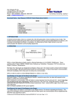
Figure 2 shows the Front panel of the SRS.
Two Push buttons “Auto / Manual” and Link1 / Link2 are provided.
The Auto / Manual switch toggles between Auto and Manual modes. In Auto mode, in case of Link failure,
Links are automatically selected or switched over. In Manual mode, Link1 / Link2 Push button toggles between
Link1 and Link2.
Corresponding LED’s indicate the current mode of operation and the Link that is
active. The default setting at Power ON is Auto mode.
The SRS2–1 has 3 Ports. These 3 Ports can be individually set for either of RS232 or RS485 - 2 wire or RS485
- 4 wire interface with the help of link settings provided on the PCB, inside the Switch.
The RS485 Signals of all Ports are provided on the 4-pin Howder terminals.
In the case of RS485-2 wire, 2 pins on this connector will be unused.
For RS232 Common Port of the SRS, 9 pin D type Male connector and for remaining 2 Ports, 9 Pin D type
Female connector are used.
The Ground of all 3 ports is Common.
In the Auto mode the Link selection will be done automatically depending up on the Activity on the Ports.
The relevant LED indications, to indicate Auto / Manual and the Active Link will be provided on the front
panel
2
SRS provides the users with the flexibility of selecting all the 3 ports as RS232 or RS485. The 485
signals are connected to the Howder connectors & the RS232 signals are to be connected on the D
type connector. Please note that this is factory setting & cannot be altered by the user very easily.
The baud rate of RS232 side is Auto adjustable. The baud rate on the RS485 side is done through
the switch setting.
The 485 side Howder connectors have “ Link “ & “ Common “ stickers pasted on them. These
connectors have to be connected on the respective Input ( Link ) or Output ( Common ) side of the
SRS and cannot be swapped.
The SRS would malfunction is the connectors are swapped.
The Time out is default factory set at 1 sec. Any other time out is also possible. Please note that
this is factory setting & cannot be altered by the user.
4. Time Out
Configuration:
In the new version of the SRS the change over Delay can be programmed according to the user’s
requirement. Once configured the desired delay it gets stored in the Non Volatile RAM of the
SRS. This document explains how to program this delay.
How to configure through
Serial Port ?
The SRS can be configured from COMMON Port when it is set for RS232 Mode. For configuring
the SRS you need to connect the COMMON Port of SRS to the serial port of the PC through 3
wire cross cable. The cross cable is as shown in the following diagram.
On PC side you need to have some
terminal software utility like Hyper
Terminal. With OS like Win95,
Win98, Win 2000 etc. it comes by
default along with OS. After
connecting SRS to the PC Com port
and starting it in Configuration
mode, SRS sends text message to the
Hyper Terminal. These messages are
arranged in the menu like style. Here
user has to select desired options and
set the parameters. In short this is an
interactive session initiated by the SRS.
To get a better idea you can refer to
below figure which shows a tree view
of the menu options offered by the
interactive configuration session.
You can follow below steps in order to configure different
parameters of the SRS
STEP :1
Ensure that COMMON Port of the SRS is set for RS232 mode. If it is not in the RS232 Mode then
make proper link setting in order to bring it in the RS232 Mode. Connect SRS to the PC COM port
through cross cable; open the HyperTerminal utility of the PC. The Hyper Terminal utility can be
selected from Start Button. Click Start button and follow this path: Start->Programs
>Communications->Hyper Terminal. It can be done as shown in the following picture. Now click
on the Hyper Terminal Menu Option.
While Hyper Terminal is on the way to start message as shown in the following screen appears:
Step2:
Name the Hyper Terminal File and press Enter key. This file can be saved and retrieved
for the future reference.
Step3:
Screen as shown in the following picture appears. Select Connect to Tab and select the appropriate
Com Port from the Combo box and click on the Configure button.
Step4:
Here you have to set Baud
Rate, Data Bits, Parity, Stop
bits and Flow Control. Set
Baud rate as 9600, Data Bits
as 8 Parity as None and Stop
Bits as1.
1 which is as desired.
Step5:
Now following screen will
appear. On the left hand
bottom corner of the Hyper
Terminal application it will
show the status as connected.
In the Next two text boxes it
shows the baud rate in auto
detection mode. Some times
with auto detection mode
Hyper Terminal does not work
properly. Hence click on the
Disconnect button in the tool
bar of the HyperTerminal.
Now disconnected status will
appear in the Left hand bottom
corner text box. Click on the
file menu and then click on the
Properties
submenu.
The
Property Page appears. Now
follow instruction same as
Step3 and Step4. The third text
box in the bottom shows the
baud rate setting as 9600 8-N-
Step 6 : Select the Settings Tab from the Property page. Form as shown in the following picture is
displayed. Click on the ASCII Set Up button
Step 7:
Following screen shows the ASCII Setup page. Click on the ‘Echo typed characters locally’ check
box.
Whatever characters you type in the Hyper Terminal utility are displayed locally in the text box of the
Hyper Terminal. Press the Ok button on the ASCII Setup Page. Now press the Ok button on the
Settings Tab of the Property Page. Click on the Connect button of the tool bar. The status is shown as
Connected.
Step8
Ensure that SRS is switched off
and cross cable is connected
between COMMON Port of the
SRS and the PC Com Port which
you have selected in the Hyper
Terminal. Now see that Hyper
Terminal utility is selected on
your PC and Caps Lock is on.
Now press ‘C’ from the key
board. While you have pressed the
‘C’ switch on the SRS. Keep
letter ‘C’
pressed for 2 seconds and release
the key. Now you can observe
that the SRS has entered in to the
Configuration
mode.
The
Configuration menu appears in
the Hyper Terminal window. The
configuration is menu driven
and is very simple.
The main menu displays 3
options which are a> View
Delay b>Edit Delay c>Exit.
Step9
If you desire to view the delay
(Current Setting) then just press
‘1’. You will see the current
setting on the screen. Following
screen
is
displayed.
Step10
Similarly if you desire to edit the delay (Current Setting) then just press ‘2’. You will see the current setting
on the screen and also you will be able to enter the new setting. The modified setting can be viewed again by
pressing 1. After dong modification you can come out of the configuration mode by pressing ‘3’ i.e. Exit Option.
5. TECHNICAL SPECIFICATIONS
Communication Ports 3 Ports for RS232.
3 Ports for RS485 2Wire / 4 Wire.
Indications Each port has 2 Red colored LED’s indicating Transmit (Tx)
and Receive (Rx) signals.
2 LED’s for indicating Auto / Manual Mode.
2 LED’s for indicating Link1, Link2 selection in Manual Mode.
Connectors RS485 ports : 4 Pin Howder connector.
RS232 ports : DB9 Female for Common & DB9 Male for
others. Power
: 3 Pin molded plug.
Toggle Switches 2 nos. For Auto / Manual & Link Selection.
Dimensions 170 x 122 x 33 mm.
Weight
Approx. 500 gms.
Mounting Wall Mounting / Table-Top.
Power Supply 90V to 270VAC @ 50 Hz Input.
Power Consumption Less than 3 watt.
Environmental Operating Temperature : 0 °C to 55 °C.
Relative Humidity
: 10 to 90 %.
6. WIRING DETAILS
For RS485, 4 wire
SIGNAL of SRS
TX +
TX -RX +
RX --
Will Connect to
RX + of your device.
RX -- of your device.
TX + of your device.
TX – of your device.
For
RS
SIGNAL of SRS
TX +
TX --
485,
2
wire
Will Connect to
TX + of your device.
TX -- of your device.
For RS232 Input ( Link ) ports
Use a Straight cable to ensure that RX, TX & Gnd signals available on Pin 2,3 & 5 respectively, on the SRS, to
be connected to RX, TX & GnD signals of your devices.
For RS232 Output ( Common ) port
Use a Cross cable to ensure that RX, TX & Gnd signals available on Pin 2,3 & 5 respectively, on the SRS, to be
connected to TX, RX & GnD signals of your devices.
7. JUMPER SETTINGS
In the event the Port type needs to be changed
from RS232 to RS485 or vica versa or the Baud
rate of the RS485 needs to be changed, the SRS
has to be opened and the Jumper settings needs to
be changed. Below are the details given. However,
we recommend that these changes be done only by
the experts under our guidance.
PCB LAYOUT (Solder Side)
CONNECTION MODE SETTINGS
Link
RS232 Mode
For Common Port
J14
Short 1 & 2
J15
Don’t Care
For Link 1 Port
J1
Short 1 & 2
J2
Don’t Care
For Link 2 Port
J3
Short 1 & 2
J4
Don’t Care
RS485 2-Wire Mode
RS485 4-Wire Mode
Short 2 & 3
Short 2 & 3
Short 2 & 3
Short 1 & 2
Short 2 & 3
Short 2 & 3
Short 2 & 3
Short 1 & 2
Short 2 & 3
Short 1 & 2
Short 2 & 3
Short 2 & 3
BAUD RATE SETTINGS (Applicable only if using RS485 Mode)
Baud Rate
1200 – 2400
For Common Port
J9
Short 5 & 6
For Link 1 Port
J7
Short 5 & 6
For Link 2 Port
J8
Short 5 & 6
NOTE:
4800 – 9600
19200 – 38400
Short 3 & 4
Short 1 & 2
Short 3 & 4
Short 1 & 2
Short 3 & 4
Short 1 & 2
For J10 : Always Short 1 & 2.
For J11 : Always Short 2 & 3.
P.O Box: 234911, Dubai, UAE
Tel
: +971-4-2955966
Fax
: +971-4-2955977
E-mail : [email protected]