1
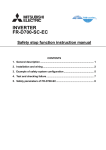
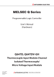
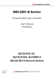
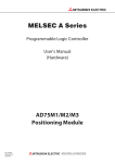
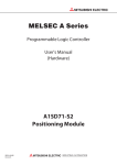
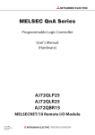
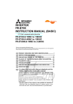
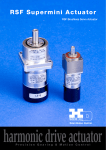
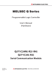
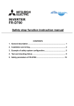
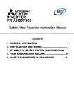
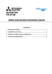
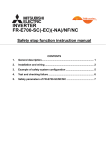
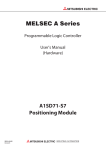
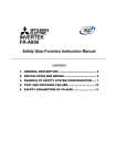
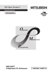
INVERTER
FR-D700-SC-EC
Safety stop function instruction manual
CONTENTS
1. General description ............................................................................. 1
2. Installation and wiring ......................................................................... 2
3. Example of safety system configuration ........................................... 5
4. Test and checking failure .................................................................... 7
5. Safety parameters of FR-D700-SC...................................................... 8
Compliance with the EU Machinery Directive – Functional Safety
WARNING
Any misuse of safety function could lead to personal injury or death, property damage, or economic loss.
To ensure that the system complies fully with requirement of safety, make a system-level risk assessment.
Mitsubishi Electric Co. cannot assume responsibility for any system to comply with safety directive.
CAUTION
The information of this manual is merely a guide for proper installation.
Mitsubishi Electric Co. cannot assume responsibility for the compliance or the noncompliance to any code,
national, local or otherwise for the proper installation of this equipment.
A hazard of personal injury and/or equipment damage exists if codes are ignored during installation.
WARNING
To avoid an electric shock hazard, verify that the voltage on the bus capacitors has discharged before
performing any work on the drive. Measure the DC bus voltage at the P(+) and N(-) terminals or test points
(refer to your drive’s User Manual for locations and discharging time). The voltage must be zero.
WARNING
The safety stop function do not isolate electrically between drive and motor. To avoid an electric shock
hazard, disconnect/isolate power to the drive and verify to ensure that the voltage is zero before
performing any work on the motor (refer to your drive’s User Manual for discharging time).
CAUTION
This instruction manual is compatible with FR-D700-SC-EC source-logic safety terminal model. For
FR-D700-EC sink-logic safety terminal model, refer to the FR-D700 safety stop function instruction manual
(BCN-A211508-000).
1. General description
Features
Mitsubishi FR-D700-SC safety stop function prevents a drive from supplying rotational energy to motors.
Dual safety channels ‘S1’ and ‘S2’ cut off the gate-drive power for IGBT to turn off.
Input power
FR-D700-SC
S1
S2
Internal
Safety
Circuit
Safety relay module
+24V
CPU
G
G
Gate
Driver
Gate
Driver
IGBTs
SC
M
Fig.1 FR-D700-SC safety stop function diagram
WARNING
The safety stop function doesn’t isolate electrically between drive and motor. To avoid an electric shock
hazard, disconnect power to the drive and verify that the voltage is zero before performing any work on the
motor (refer to your drive’s User Manual for discharging time).
Directives
Mitsubishi FR-D700-SC safety stop function meets the following directives and categories.
ISO13849-1:2008 Category 3/PLd
IEC62061:2005 / IEC61800-5-2:2007 / IEC61508 SIL2
IEC60204-1:2006 / IEC61800-5-2:2007 Stop category 0
WARNING
The misuse of safety function leads to personal injury or death, property damage, or economic loss.
To ensure that the system complies fully with requirement of safety, make a system-level risk assessment.
Mitsubishi Electric Co. cannot assume responsibility for any system to comply with safety directive.
1
2. Installation and wiring
CAUTION
The following information is merely a guide for proper installation.
Mitsubishi Electric Co. cannot assume responsibility for the compliance or the noncompliance to any code,
national, local or otherwise for the proper installation of this equipment.
A hazard of personal injury and/or equipment damage exists if codes are ignored during installation.
CAUTION
Ensure the safety relay unit and the FR-D700-SC unit is mounted closely in enclosure meeting IP54 and
all interconnection wiring is short and protected against open and short circuit faults.
Refer EN/ISO13849-2.
Installation
Mitsubishi FR-D700-SC safety stop function should be used under following condition and environment.
Table.1 The condition and environment for using safety stop function
Item
Temperature
Operation
range
Storage
Ambient humidity
Vibration
Altitude
Atmosphere
Over voltage category
Pollution degree
Mounting
Condition
-10°C to +50°C (non-freezing)
-20°C to +65°C
90%RH maximum (non-condensing)
5.9m/s2 or less
maximum 1000m above sea level
Indoors (without corrosive gas, flammable gas, oil mist, dust and dirt etc.)
II or less
II or less
wall mounting / vertical orientation
CAUTION
In order to meet safety stop, an approved safety relay unit to ISO13849-1/EN954-1 safety category 3 or better shall be
used in conjunction with FR-D700-SC as shown in example1,2.
In addition, all other components with in the safety stop loop shall be ‘safety approved’ types.
WARNING
To avoid an electric shock hazard, insert the magnetic contactor (MC) between power source and drive.
Open the contact of MC and keep away from drive for discharging time (refer to your drive’s User Manual
for information) before performing any work on the drive.
And verify that the voltage on the bus capacitors has discharged before Measure the DC bus voltage at the
P(+) and N(-) terminals or test points (refer to your drive’s User Manual for locations). The voltage must be
zero.
CAUTION
To avoid systematic faults, a test even for faulty demands of the safety function has to be performed in order to check
the correct function of the monitor signal. This test shall be carried out at system installation, any software changes,
parameterization changes, and/or at least once per year.
Refer to ‘4. Test and checking failure’.
2
Wiring
The safety related terminals are described in Table.2 and Table.3
Table.2 The safety related terminals
Terminal
Symbol
S1
S2
SC
SO
(SAFE)
RUN
(SAFE2)
SE
Description
Rating
For input of safety stop channel1.
S1-SC is
Open: In safety stop mode.
Short: Non safety stop mode.
For input of safety stop channel2.
S2-SC is
Open: In safety stop mode.
Short: Non safety stop mode.
Common terminal for S1, S2 terminals.
*SC is connected terminal PC internally.
Input resistance:4.7kΩ
Current : 4 to 6 mA
(In case of shorted to SC)
Voltage : 21 to 26 V
(In case of open from SC)
As output for safety stop condition.
SO terminal type is ‘Open collector output’.
SO-SE is
OFF(Open): Drive enabled, or drive shutoff (with
internal circuit fault)
ON(Close): Drive shutoff (no internal circuit fault)
Important: SO terminal should be used for monitoring safety stop
condition only. SO terminal cannot be used for safety function.
As output for failure detection and alarm. RUN terminal type is ‘Open
collector output’.
RUN-SE is
OFF(Open): Detect failure or Alarm.
ON(Close): No failure detected.
Attention: To use RUN terminal for monitor output of failure
detection, The parameter No.190 should be set 81
(Safety monitor 2).
Note: This terminal can be used for alarm or to prevent restart only,
no other safety function.
Common terminal for safety RUN and SO terminal.
3
Load: 24VDC/0.1A max.
Voltage drop: 3.4V max.
(In case of ‘ON’ state)
Table.3 Truth table of Safety related signals
Input power
S1-SC
S2-SC
OFF
-
-
Short
Short
Open
Open
Short
Open
Open
Short
ON
Internal safety
circuit fault *1
No failure
Detected
No failure
Detected
N/A
N/A
SO (SAFE)
RUN (SAFE2) *2
Drive state
OFF(Open)
OFF(Open)
Drive shutoff (Safe state)
OFF(Open)
ON(Close)
Drive enable
OFF(Open)
OFF(Open)
Drive shutoff (Safe state)
ON(Close)
ON(Close)
Drive shutoff (Safe state)
OFF(Open)
OFF(Open)
Drive shutoff (Safe state)
OFF(Open)
OFF(Open)
Drive shutoff (Safe state)
OFF(Open)
OFF(Open)
Drive shutoff (Safe state)
" N/A " denotes a condition where circuit fault does not apply.
*1
At an internal safety circuit fault, one of E.SAF or E.CPU is displayed on the operation panel. SA is displayed on the operation
*2
To use RUN terminal for monitor output of failure detection, the parameter No.190 should be set 81 (Safety monitor 2).
panel while S1 and S2 signals are both open and the safety function operates (without internal safety circuit fault).
Wire and ferrule specification
Table.4 wire and ferrule specification
Wire size (mm )
Ferrule with insulation collar *
0.3 / 0.5
AI 0,5-10WH
0.75
AI 0,75-10GY
1
AI 1-10RD
1.25 / 1.5
AI1,5-10BK
0.75 (combined 2 wire)
AI TWIN 2 X 0,75-10GY
*Ferrules and tools are distributed by Phoenix Contact.
2
Crimping tool *
CRIMPFOX 6
Jumper cable
The jumper cable between S1,S2 and SC terminal has been installed in the factory as shown in Fig.2.
AM
Fig.2. Short wire
Before connecting safety input wire to S1,S2 and SC terminal, remove this jumper cable.
4
3. Example of safety system configuration
R/L1 S/L2 T/L3
RUN (SAFE2)
SE
STF
START
STF
Emergency
stop button
STOP
+24V
X0
COM0
X1
Internal
Safety
Circuit
DC24V
COM1
XS0
XS1
Z00
IGBTs
CPU
STOP
Z10
Z20
Gate
Driver
Gate
Driver
G
G
S2
K1
S1
K2
+24V
24G
Z01
MITSUBISHI MELSEC Safety relay module
QS90SR2SN-Q
Z11
Z21
SC
PC
FR-D700-SC
U
V
W
IM
Fig.3 Safety system example – STOP synchronous with emergency stop button and fault
detection through RUN output.
For safety stop, configure the wiring as shown in Fig.3 above.
Note: the above wiring is configured to prevent restart in case of a fault.
XS0 should be connected to RUN terminal and XS1 should be connected to SE, because polarity of XS0 is
positive, XS1 is negative.
The parameter No.190 (RUN terminal function selection) must be set to ‘81’. This setting makes the RUN
output to turn off in case of failure.
After the power-up, to reset the safety stop mode, press the START switch, and also press the STF switch,
then start the motor rotation.
In the above Fig.3, wired example, in the event of reset of ‘safe-condition’ the motor rotation will not occur
until STF is pressed.
(for normal ‘non-safety’ STF/STOP function, please refer to your drive’s User Manual)
CAUTION
To prevent restart in case of recovering from input power loss of drive, 3-wired connection for STF/STOP
control is recommended.
In case of 2-wire connection and using latching type switch to short between STF and PC for starting,
ensure the compliance with safety requirement for the restarting when the drive recover from input power
loss.
5
R/L1 S/L2 T/L3
RUN (SAFE2)
SE
START
Emergency
stop button
+24V
X0
COM0
X1
Internal
Safety
Circuit
DC24V
IGBTs
CPU
COM1
XS0
XS1
Z00
Z10
Z20
S1
Gate
Driver
Gate
Driver
G
G
K1
S2
K2
+24V
24G
Z01
Z11
Z21
SC
MITSUBISHI MELSEC Safety relay module
QS90SR2SN-Q
FR-D700-SC
U
V
W
IM
R/L1 S/L2 T/L3
RUN
(SAFE2)
SE
IGBTs
CPU
S1
Gate
Driver
Gate
Driver
G
G
S2
+24V
SC
FR-D700-SC
U
V
W
IM
Fig.4 Example when using multiple FR-D740-SC inverters for the safety stop function
The parameter No.190 (RUN terminal function selection) must be set to ‘81’. This setting makes the RUN
output to turn off in case of failure.
NOTE
Do not connect the FR-D700 sink-logic safety terminal model together with FR-D700-SC source-logic
safety terminal model. If connected together, the safety stop function does not work properly.
6
4. Test and checking failure
CAUTION
To avoid systematic faults, a test even for faulty demands of the safety function has to be performed in order to check
the correct function of the monitor signal. This test shall be carried out at system installation, any software changes,
parameterization changes, and/or at least once per year.
I/O status and failure
FR-D700-SC safety related I/O status obeys the following truth table.
Table.5 Truth table of Safety related signals
Input power
S1-SC
S2-SC
OFF
-
-
Short
Short
Open
Open
Short
Open
Open
Short
ON
Internal safety
circuit fault *1
No failure
Detected
No failure
Detected
N/A
N/A
SO (SAFE)
RUN (SAFE2) *2
Drive state
OFF(Open)
OFF(Open)
Drive shutoff (Safe state)
OFF(Open)
ON(Close)
Drive enable
OFF(Open)
OFF(Open)
Drive shutoff (Safe state)
ON(Close)
ON(Close)
Drive shutoff (Safe state)
OFF(Open)
OFF(Open)
Drive shutoff (Safe state)
OFF(Open)
OFF(Open)
Drive shutoff (Safe state)
OFF(Open)
OFF(Open)
Drive shutoff (Safe state)
" N/A " denotes a condition where circuit fault does not apply.
*1
At an internal safety circuit fault, one of E.SAF or E.CPU is displayed on the operation panel. SA is displayed on the operation
*2
To use RUN terminal for monitor output of failure detection, the parameter No.190 should be set 81 (Safety monitor 2).
panel while S1 and S2 signals are both open and the safety function operates (without internal safety circuit fault).
In case of diagnostic or functionality test, check the I/O state whether it is same or not as Table.5.
Diagnostic
If the failure detected, FR-D700-SC output alarm signal and indicate ‘E.SAF’ at the display.
In case of FR-D700-SC output the alarm, please take following action.
(1) Check the S1-SC and S2-SC input signal logic is the same. If these are different logic, correct the input
signal and reset the FR-D700-SC.
(2) Disconnect the wire from S1, S2, SC terminal, then reset or power-off and on, If the ‘SA’ letter is
flashed up at display, there is failure in system except FR-D700-SC. But, still ‘E.SAF’ is displayed and
alarm output, there is malfunction on FR-D700-SC.
Self diagnostic test
FR-D700-SC does the self-diagnostic test on the power-ON.
If FR-D700-SC output alarm at power-ON, please take the action described in ‘Diagnostic’ at above.
Test procedure for functionality
As depicted ‘ATTENTION’ in above, the test for the functionality is important.
Please do the test following procedure.
(1) Please make each state of S1-SC and S2-SC depicted at Table.5.
(2) If there is any different state from Table.5, FR-D700-SC has some malfunction.
(3) If there is no different state from Table.5, check the systematic performance, such as, press the
Emergency switch, press the start/restart button at the failure detected (RUN-SE opened), and so on.
(4) Finally clear the error record of the FR-D700-SC (see the user manual how to clear the error record).
7
5. Safety parameters of FR-D700-SC
FR-D700-SC safety related I/O status obeys the following truth table.
Table.6 Safety parameters of FR-D700-SC
Parameter
PFDAVG
PFHD
PL
MTTFD
DCAVG
Value
2.06x10⁻⁴
2.35x10⁻⁹
d
725 years
60%
8
REVISIONS
Print Date
Manual Number
Jan. 2012
BCN-A211508-005-A
BCN-A211508-005-A
Revision
First edition
9
MITSUBISHI ELECTRIC
HEADQUARTERS
EUROPEAN REPRESENTATIVES
EUROPEAN REPRESENTATIVES
MITSUBISHI ELECTRIC EUROPE B.V.
EUROPE
German Branch
Gothaer Straße 8
D-40880 Ratingen
Phone: +49 (0)2102 / 486-0
Fax: +49 (0)2102 / 486-1120
MITSUBISHIELECTRICEUROPEB.V.-org.sl. CZECH REP.
Czech Branch
Avenir Business Park, Radlická 714/113a
CZ-158 00 Praha 5
Phone: +420 - 251 551 470
Fax: +420 - 251-551-471
MITSUBISHI ELECTRIC EUROPE B.V.
FRANCE
French Branch
25, Boulevard des Bouvets
F-92741 Nanterre Cedex
Phone: +33 (0)1 / 55 68 55 68
Fax: +33 (0)1 / 55 68 57 57
MITSUBISHI ELECTRIC EUROPE B.V.
IRELAND
Irish Branch
Westgate Business Park, Ballymount
IRL-Dublin 24
Phone: +353 (0)1 4198800
Fax: +353 (0)1 4198890
MITSUBISHI ELECTRIC EUROPE B.V.
ITALY
Italian Branch
Viale Colleoni 7
I-20041 Agrate Brianza (MB)
Phone: +39 039 / 60 53 1
Fax: +39 039 / 60 53 312
MITSUBISHI ELECTRIC EUROPE B.V.
POLAND
Poland Branch
Krakowska 50
PL-32-083 Balice
Phone: +48 (0)12 / 630 47 00
Fax: +48 (0)12 / 630 47 01
MITSUBISHI ELECTRIC EUROPE B.V.
RUSSIA
52, bld. 3 Kosmodamianskaya nab 8 floor
RU-115054 Мoscow
Phone: +7 495 721-2070
Fax: +7 495 721-2071
MITSUBISHI ELECTRIC EUROPE B.V.
SPAIN
Spanish Branch
Carretera de Rubí 76-80
E-08190 Sant Cugat del Vallés (Barcelona)
Phone: 902 131121 // +34 935653131
Fax: +34 935891579
MITSUBISHI ELECTRIC EUROPE B.V.
UK
UK Branch
Travellers Lane
UK-Hatfield, Herts. AL10 8XB
Phone: +44 (0)1707 / 27 61 00
Fax: +44 (0)1707 / 27 86 95
MITSUBISHI ELECTRIC CORPORATION
JAPAN
Office Tower “Z” 14 F
8-12,1 chome, Harumi Chuo-Ku
Tokyo 104-6212
Phone: +81 3 622 160 60
Fax: +81 3 622 160 75
MITSUBISHI ELECTRIC AUTOMATION, Inc.
USA
500 Corporate Woods Parkway
Vernon Hills, IL 60061
Phone: +1 847 478 21 00
Fax: +1 847 478 22 53
GEVA
AUSTRIA
Wiener Straße 89
AT-2500 Baden
Phone: +43 (0)2252 / 85 55 20
Fax: +43 (0)2252 / 488 60
TECHNIKON
BELARUS
Oktyabrskaya 19, Off. 705
BY-220030 Minsk
Phone: +375 (0)17 / 210 46 26
Fax: +375 (0)17 / 210 46 26
ESCO DRIVES & AUTOMATION
BELGIUM
Culliganlaan 3
BE-1831 Diegem
Phone: +32 (0)2 / 717 64 30
Fax: +32 (0)2 / 717 64 31
Koning & Hartman b.v.
BELGIUM
Woluwelaan 31
BE-1800 Vilvoorde
Phone: +32 (0)2 / 257 02 40
Fax: +32 (0)2 / 257 02 49
INEA RBT d.o.o.
BOSNIA AND HERZEGOVINA
Aleja Lipa 56
BA-71000 Sarajevo
Phone: +387 (0)33 / 921 164
Fax: +387 (0)33 / 524 539
AKHNATON
BULGARIA
4, Andrei Ljapchev Blvd., PO Box 21
BG-1756 Sofia
Phone: +359 (0)2 / 817 6000
Fax: +359 (0)2 / 97 44 06 1
INEA RBT d.o.o.
CROATIA
Losinjska 4 a
HR-10000 Zagreb
Phone: +385 (0)1 / 36 940 - 01/ -02/ -03
Fax: +385 (0)1 / 36 940 - 03
AutoCont C.S. s.r.o.
CZECH REPUBLIC
Technologická 374/6
CZ-708 00 Ostrava-Pustkovec
Phone: +420 595 691 150
Fax: +420 595 691 199
Beijer Electronics A/S
DENMARK
Lykkegårdsvej 17
DK-4000 Roskilde
Phone: +45 (0)46/ 75 76 66
Fax: +45 (0)46 / 75 56 26
Beijer Electronics Eesti OÜ
ESTONIA
Pärnu mnt.160i
EE-11317 Tallinn
Phone: +372 (0)6 / 51 81 40
Fax: +372 (0)6 / 51 81 49
Beijer Electronics OY
FINLAND
Peltoie 37
FIN-28400 Ulvila
Phone: +358 (0)207 / 463 540
Fax: +358 (0)207 / 463 541
UTECO
GREECE
5, Mavrogenous Str.
GR-18542 Piraeus
Phone: +30 211 / 1206 900
Fax: +30 211 / 1206 999
MELTRADE Kft.
HUNGARY
Fertő utca 14.
HU-1107 Budapest
Phone: +36 (0)1 / 431-9726
Fax: +36 (0)1 / 431-9727
Beijer Electronics SIA
LATVIA
Ritausmas iela 23
LV-1058 Riga
Phone: +371 (0)784 / 2280
Fax: +371 (0)784 / 2281
Beijer Electronics UAB
LITHUANIA
Savanoriu Pr. 187
LT-02300 Vilnius
Phone: +370 (0)5 / 232 3101
Fax: +370 (0)5 / 232 2980
ALFATRADE Ltd.
MALTA
99, Paola Hill
Malta- Paola PLA 1702
Phone: +356 (0)21 / 697 816
Fax: +356 (0)21 / 697 817
INTEHSIS srl
MOLDOVA
bld. Traian 23/1
MD-2060 Kishinev
Phone: +373 (0)22 / 66 4242
Fax: +373 (0)22 / 66 4280
HIFLEX AUTOM.TECHNIEK B.V.
NETHERLANDS
Wolweverstraat 22
NL-2984 CD Ridderkerk
Phone: +31 (0)180 – 46 60 04
Fax: +31 (0)180 – 44 23 55
Koning & Hartman b.v.
NETHERLANDS
Haarlerbergweg 21-23
NL-1101 CH Amsterdam
Phone: +31 (0)20 / 587 76 00
Fax: +31 (0)20 / 587 76 05
Beijer Electronics AS
NORWAY
Postboks 487
NO-3002 Drammen
Phone: +47 (0)32 / 24 30 00
Fax: +47 (0)32 / 84 85 77
Fonseca S.A.
PORTUGAL
R. João Francisco do Casal 87/89
PT - 3801-997 Aveiro, Esgueira
Phone: +351 (0)234 / 303 900
Fax: +351 (0)234 / 303 910
Sirius Trading & Services srl
ROMANIA
Aleea Lacul Morii Nr. 3
RO-060841 Bucuresti, Sector 6
Phone: +40 (0)21 / 430 40 06
Fax: +40 (0)21 / 430 40 02
INEA RBT d.o.o.
SERBIA
Izletnicka 10
SER-113000 Smederevo
Phone: +381 (0)26 / 615 401
Fax: +381 (0)26 / 615 401
SIMAP s.r.o.
SLOVAKIA
Jána Derku 1671
SK-911 01 Trencín
Phone: +421 (0)32 743 04 72
Fax: +421 (0)32 743 75 20
PROCONT, spol. s r.o. Prešov
SLOVAKIA
Kúpelná 1/A
SK-080 01 Prešov
Phone: +421 (0)51 7580 611
Fax: +421 (0)51 7580 650
INEA RBT d.o.o.
SLOVENIA
Stegne 11
SI-1000 Ljubljana
Phone: +386 (0)1 / 513 8116
Fax: +386 (0)1 / 513 8170
Beijer Electronics AB
SWEDEN
Box 426
SE-20124 Malmö
Phone: +46 (0)40 / 35 86 00
Fax: +46 (0)40 / 93 23 01
Omni Ray AG
SWITZERLAND
Im Schörli 5
CH-8600 Dübendorf
Phone: +41 (0)44 / 802 28 80
Fax: +41 (0)44 / 802 28 28
GTS
TURKEY
Bayraktar Bulvari Nutuk Sok. No:5
TR-34775 Yukarı Dudullu-Ümraniye-İSTANBUL
Phone: +90 (0)216 526 39 90
Fax: +90 (0)216 526 3995
CSC Automation Ltd.
UKRAINE
4-B, M. Raskovoyi St.
UA-02660 Kiev
Phone: +380 (0)44 / 494 33 55
Fax: +380 (0)44 / 494-33-66
Systemgroup
UKRAINE
2 M. Krivonosa St.
UA-03680 Kiev
Phone: +380 (0)44 / 490 92 29
Fax: +380 (0)44 / 248 88 68
EURASIAN REPRESENTATIVES
TOO Kazpromavtomatika
Ul. Zhambyla 28
KAZ-100017 Karaganda
Phone: +7 7212 / 50 10 00
Fax: +7 7212 / 50 11 50
KAZAKHSTAN
MIDDLE EAST REPRESENTATIVE
SHERF Motion Techn. Ltd.
ISRAEL
Rehov Hamerkava 19
IL-58851 Holon
Phone: +972 (0)3 / 559 54 62
Fax: +972 (0)3 / 556 01 82
CEG INTERNATIONAL
LEBANON
Cebaco Center/Block A Autostrade DORA
Lebanon - Beirut
Phone: +961 (0)1 / 240 430
Fax: +961 (0)1 / 240 438
AFRICAN REPRESENTATIVE
CBI Ltd.
Private Bag 2016
ZA-1600 Isando
Phone: + 27 (0)11 / 977 0770
Fax: + 27 (0)11 / 977 0761
SOUTH AFRICA
Mitsubishi Electric Europe B.V. /// FA - European Business Group /// Gothaer Straße 8 /// D-40880 Ratingen /// Germany
Tel.: +49(0)2102-4860 /// Fax: +49(0)2102-4861120 /// [email protected] /// www.mitsubishi-automation.com