1
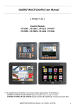
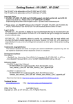
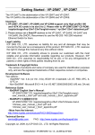
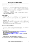
Linking ISaGRAF PAC to Modbus TCP/IP Slave
Devices By Modbus TCP Master Protocol
By [email protected]
ISaGRAF PAC WP-8xx7 and VP-25W7/23W7 and XP-8xx7-CE6 support Modbus TCP/IP
Master Protocol to link to various Standard Modbus TCP/IP Slave devices using the following
version drivers:
The following version supports “Mbus_tcp”
WP-8xx7: driver Ver.1.14 or later ,
VP-25W7/23W7: driver Ver.1.05 or later
XP-8xx7-CE6 : driver Ver.1.02 or later
The following version supports “Mbus_tcp” and “Mbus_tc2”
WP-8xx7: driver Ver.1.23 or later ,
VP-25W7/23W7: driver Ver.1.14 or later
XP-8xx7-CE6 : driver Ver.1.03 or later
To send Modbus TCP commands with different NET-ID number to the same Modbus TCP
slave device, please use the following ISaGRAF driver (refer to the section 1.4)
WP-8xx7: driver Ver.1.52 or later ,
VP-25W7/23W7: driver Ver.1.44 or later
XP-8xx7-CE6 : driver Ver.1.32 or later
User may download the latest version of driver from:
http://www.icpdas.com/products/PAC/i-8000/isagraf-link.htm
Each WP-8xx7 or VP-25W7/23W7 or XP-8xx7-CE6 can link to up to 100 Modbus TCP/IP
slave devices. Please make sure the driver version of PAC is consistent with the above listed
versions.
ISaGRAF FAQ-113 Feb.25,2013
1
ICP DAS
The following listed ISaGRAF driver version support up to 1000 mbus_xxx function blocks
(amount sum of all Mbus_B_r, Mbus_B_W, Mbus_N_r, Mbus_N_W, Mbus_R, ...) for each
“mbus_tcp” (or “mbus_tc2”) in one project . While older driver version can support only 255.
WP-8xx7: driver Ver.1.57 or later
,
VP-25W7/23W7/4137: driver Ver.1.49 or later
XP-8xx7-CE6 : driver Ver.1.37 or later , WP-5147: driver Ver. 1.04 or later
XP-8xx7-ATOM-CE6: driver Ver. 1.02 or later.
The “Mbus_AR” and “Mbus_AW” function blocks can reduce the Mbus code size. Please
refer to www.icpdas.com > FAQ > Software > ISaGRAF> English > 161.
Then, make sure the I/O complex equipment - “mbus_tcp” and “mbus_tc2” are installed in the
PC/ISaGRAF. If not, please download them from the following website:
www.icpdas.com > FAQ > Software > ISaGRAF> English > 113
Then follow the steps to install it to the PC/ISaGRAF.
ISaGRAF FAQ-113 Feb.25,2013
2
ICP DAS
1.1 Using “Mbus_tcp” or “Mbus_tc2” to Link Modbus
TCP/IP Slave Devices
1. Setup for using “Mbus_tcp” and “Mbus_tc2”
The “Mbus_tcp” is for connecting devices which have only one IP address.
The “Mbus_tc2” is for connecting devices which have two IP address. (There is one more
setting - “Device_IP2”. If one fail, the PAC will try to connect the other IP )
One PAC supports up to 100 “Mbus_tcp” connections. Using more “Mbus_tcp” connections
will reduce the PAC efficiency. If the PAC does not actually connect to a Modbus TCP/IP
slave device, do not use “Mbus_tcp” assigned with its IP address. It is to prevent the PAC
efficiency reducing from trying to connect a non-existing device.
Some Modbus TCP/IP slave devices may not allow read/write data in fast frequency. The
user can assign a larger value to “Min_Wait_Time”, so that the Modbus TCP/IP command will
not be sent too frequent.
Device_IP: the IP address of
the linked device.
Device_NET_ID: the NET-ID
number of the device.
(Usually is number 1)
Timeout: unit ms (0.001sec.),
if got no response more than
a period time, set as timeout .
(default is 2000)
Min_Wait_Time: unit ms, the
minimum waiting time before
sending the next MBTCP
command. (could be 10 ~
60,000).
Port_No: the Modbus TCP/IP
port used by the device.
Normally is 502.
Which_LAN : 0: auto-switch
1: always using LAN1
2. always using LAN2
“Mbus_tcp” has four Integer inputs, listed below:
The 1st Channel : return a “Mbus_tcp” ID number, the correct ID value is at least 1,000,001.
Must use it to the input parameter of the “SLAVE_” on the left side of “mbus_xxx” blocks.
The 2nd Ch. : the connection situation of the current device, 1: connecttd , 0: not connectted.
The 3rd Ch. : reserved.
The 4th Ch. : reserved.
ISaGRAF FAQ-113 Feb.25,2013
3
ICP DAS
2. Edit the “Mbus_xxx” function blocks to access to Modbus TCP/IP slave devices
After the step 1 about linking “Mbus_tcp”, next step is similar to the method listed in the
Chapter 8 - “Linking The Controller To Modbus RTU & Modbus ASCII Devices” of the
“User’s Manual of ISaGRAF PAC”. Up to now, “Mbus_tcp” supports the following Modbus
read/write function blocks.
Mbus_R
Setting “CODE_” as Modbus function code 3 or 4:
1. Read max. 12 Word-values (-32768 ~ +32767)
2. Read max. six 32-bit Integer-values (-2,147,483,648 ~ +2,147,483,647): must
transform 2 words to one 32-bit Integer-value using function block “WD_LONG”.
3. Or read max. 6 Real-values (32-bit floating point): must transform two words to
one 32-bit Integer-value using function block “WD_LONG”, then, transform that
32-bit Integer-value to one 32-bit Float-value using function block “INT_REAL”.
Setting “CODE_” as Modbus function code 1 or 2:
4. Read max. 192 Boolean(Bit)-values: must transform one word to 16 Booleanvalues using function block “WD_Bit”.
Mbus_R1
Same as “MBUS_R” but with one extra setting – “PERIOD_” (unit: sec., 1 ~ 600).
Read words or bits with a specified period time.
Mbus_N_R
Read 8 Word-values (-32768 ~ +32767) using Modbus function code 3
(Each Modbus command requests 8 Words, if the device does not support 8
Words per time or it supports Modbus function code 4 only, please use another
function block “MBUS_R”. )
Mbus_NR1
Same as “MBUS_N_R”, but with one extra - “PERIOD_” (unit: sec., 1 ~ 600).
Read words with a specified period time.
MBUS_B_R Read 8 Boolean(Bit)-values (True or False) using Modbus function code 1.
(Each Modbus command requests 8 Bits, if the device does not support 8 Bits per
time or it supports Modbus function code 2 only, please use another function block
“MBUS_R”.)
MBUS_BR1 Same as “MBUS_B_R”, but with one extra setting - “PERIOD_” (unit: sec., 1 ~
600).
Read value with a specified period time.
MBUS_N_W 1. Write max. 4 Word (-32768~+32767) using Modbus function code 6 or 16.
If “NUM_W_” is 1, use Modbus function code 6.
If “NUM_W_” is -1, use Modbus function code 16 to write 1 word.
If “NUM_W_” is 2 ~ 4, use Modbus function code 16.
2. Or write 1~2 32-bit Integer-values: use function block “LONG_WD” transform one
32-bit Integer to 2 Words, send them into “MBUS_N_W” and set “NUM_W_” as 2
or 4.
3. Or write 1~2 32-bit Float point values: use function block “REAL_INT” transform
one 32-bit Float to one 32-bit Integer, then use function block “LONG_WD”
transform the 32-bit Integer to 2 Words, send them into “MBUS_N_W” and set
“NUM_W_” as 2 or 4.
MBUS_B_W Write max. 4 bit-values using Modbus function code 5 or 15 .
If “NUM_W_” is 1, use Modbus function code 5.
If “NUM_W_” is 2 ~ 4, use Modbus function code 15.
MBUS_WB Write max. 16 bit-value using Modbus function code 15.
MBUS24R
Read max. 24 Word-values or 12 long Integer or Real values (Refer to FAQ-096)
MBUS24R1 Read max. 24 Word-values or 12 long Integer or Real values (Refer to FAQ-096)
MBUS_XR
Read max. 120 Word-values or 60 long Integer or Real values (Refer to FAQ-101)
MBUS_XR1 Read max. 120 Word-values or 60 long Integer or Real values (Refer to FAQ-101)
ISaGRAF FAQ-113 Feb.25,2013
4
ICP DAS
For example, read from the address 0 to 9 of the Modbus TCP/IP salve device. There is 10
Words (suppose the device using Modbus function code 4), so user can use function block
“Mbus_R” to read it. (“Mbus_TCP_ID1” is the first channel value returned by the “Mbus_tcp”
in the I/O connection window. It is the ID number of the “Mbus_tcp”. Please refer to the
previous step 1 for detail information.)
The first returned value in the right had side is the communication situation of the function
block “mbus_R”, True: ok, False: fail.
ISaGRAF FAQ-113 Feb.25,2013
5
ICP DAS
For another example, write 1 Bit-value to Modbus TCP/IP slave device. User can use function
block “Mbus_B_W” (or “Mbus_wb”, Note: When write 1 bit, “Mbus_b_w” uses Modbus
function code 5. But “Mbus_wb” uses Modbus function code 15. When write 2 or more Bits,
“Mbus_b_w” and “Mbus_wb” are all using the Modbus function code 15. )
In the program below, when “M9” is set to “True”, it will send the command once to set 1 bitvalue (addr=100) as B01 (B01 is an ISaGRAF Boolean variable. Its value can be “True” or
“False”.). If user wish to send the command continuously, please directly set “True” to the
parameter of “ACTION_”. The below sends the command just once when M9 is “True”.
For more information, please visit www.icpdas.com > FAQ > Software > ISaGRAF> Englich
FAQ-101 : How to read max. 120 Words or max. 60 Long-Integers or max. 60 Real values
from Modbus RTU / ASCII devices by using MBUS_XR or MBUS_XR1 function
block (for WP-8xx7 / 8xx6 and VP-25W7/23W7/25W6/23W6 and Wincon-8xx7 /
8xx6 only) ?
FAQ-096 : Release Two C-Function-Blocks To Read Max. 24 Words Or 384 Bits From
Modbus RTU / ASCII Devices
FAQ-047 : How to Read or Write Floating Point Values to Modbus RTU Slave device ?
FAQ-046 : How to Write 16-bits to Modbus RTU devices by Modbus function call No. 6 ?
FAQ-125 : The XP-8xx7-CE6 plus iDCS-8000 redundant system.
“User’s Manual of ISaGRAF PAC” Chapter 8. (“User_Manual_I_8xx7.pdf”)
WP-8xx7 CD:\napdos\isagraf\wp-8xx7\chinese_manu\ or
VP-2xW7 CD:\napdos\isagraf\vp-25w7-23w7\chinese_manu\ or
http://www.icpdas.com/products/PAC/i-8000/getting_started_manual.htm
ISaGRAF FAQ-113 Feb.25,2013
6
or
ICP DAS
1.2 Using “Mbus_tcp” to Link ET-7000 I/O Modules
ICP DAS ET-7000 series supports Modbus TCP/IP slave protocol and Web configuration.
WP-8xx7 or VP-2xW7 can link to several ET-7000 modules by using ”Mbus_tcp”. In theory a
single WP-8xx7 or VP-2xW7 can link to up to 100 pcs. of ET-7000 modules.
For more ET-7000 product information, please visit the following website.
http://www.icpdas.com/products/Remote_IO/et-7000/et-7000_selection_guides.htm
1. Using Internet Browser to setup ET-7000 module
Each ET-7000 must be configured via Internet Browser before its first usage. ET-7000 series
manufactured with the IP address=192.168.255.1 , Mask=255.255.0.0 . Please set your PC
in the same domain of IP address, ex: set PC to IP=192.168.255.100 , Mask=255.255.0.0 .
Then run the Internet Browser, such as IE, type-in the IP address to connect the ET-7000, as
the below screen (Note: The Dip Switch on the back of ET-7000 must be set to the “Normal”
position.). First, click [Configuration] > [Module I/O Settings] for the Channel setting, then
click “Submit” to set the setting .
Username : Admin
Password: Admin
(Case sensitive)
ISaGRAF FAQ-113 Feb.25,2013
7
ICP DAS
Note: After changing the IP or Mask of ET-7000, user must link it by the new IP. The PC
must also set to the same domain with the new IP address. (If forget IP or Mask
of the ET-7000, please refer to the section 1.3 of this document.)
Next, to set up the IP and Mask of the ET-7000, please click [Configuration] > [Network
Settings]. After changing IP & Mask, click “MODIFY_SETTING”.
Please use the new IP address to connect it after setting the new IP & Mask. (If forget IP or
Mask of the ET-7000, please refer to the section 1.3 of this document.)
ISaGRAF FAQ-113 Feb.25,2013
8
ICP DAS
2. Using “Mbus_tcp” & “Mbus_xxx” function blocks to link ET-7000
Next, connect the “Mbus_tcp” in the “ISaGRAF I/O connection” window (please refer to the
section 1.1 of this document). Then use the suitable function block “Mbus_xxx” to read or
write the data in the ET-7000.
For DO channel of ET-7000, please use “Mbus_WB” function block. The “NUM_” parameter
must assign in the exact DO channel amount of the ET-7000 (can be 1 to 16). Assign the
“ACTION_” parameter with “True” and the “ADDR_” with “0” (If the ET-7000 has more than
16 DO channels, using two “Mbus_wb” function blocks to control them and set one of
“ADDR_” to “0”, set the other to “16”.)
Please assign “False” to the DO
channels that been not used.
ISaGRAF FAQ-113 Feb.25,2013
9
ICP DAS
For DI channel of ET-7000, please use “Mbus_R” function block. Assign the “ADDR_” with
“0” and assign the “CODE_” with “2”. The “NUM_” parameter must assign in the exact DI
channel amount of the ET-7000 (can be 1 to 32).
Each “N1_” to “N12_” in the right hand side of the “Mbus_R” function block is a Word-value
(range: -32768 to +32767). Each Word-value can be transformed to 16 DI channel values, so
please use “WD_BIT” to transform Word to Boolean variable, as the following pictures. (Note:
If the ET-7000 has more than 16 DI channels, must use 2 words, such as N1_ and N2_, in
the right side.)
ISaGRAF FAQ-113 Feb.25,2013
10
ICP DAS
For AI channel of ET-7000, please use “Mbus_R” (or “mbus24R” ) function block. Assign
the “ADDR_” with “0” and assign the “CODE_” with “4”. The “NUM_” parameter must assign
in the exact AI channel amount of the ET-7000, could be 1 to 12 (while 1 to 24 for the
“Mbus24R” ).
The range of the Word-value read from the right side is -32768 ~ + 32767. This value is
related to the AI channel range setting of the ET-7000. Please refer to the user manual of the
ET-7000. (For example, ET-7017 : http://www.icpdas.com/products/Remote_IO/et-7000/et7017.htm > Software)
For instance, if set the range of ET-7017 to “08 : -10 V to + 10V”, its word-value is mapping to
-32768 ~ + 32767. When input 5 V, the Word-value read from the right side is about 16383; if
input -2.5 V, the Word-value is about -8192.
ISaGRAF FAQ-113 Feb.25,2013
11
ICP DAS
For AO channel of ET-7000, please use “Mbus_N_W” function block. The “NUM_W_” is
assigned in the exact AO channel amount of the ET-7000, could be 1 to 4 (If the AO channels
are more than 4, please use two or more “Mbus_N_W” blocks to control them.). “ADDR_”
must be filled in “0” and the “ACTION_” must be filled in “True”.
The range of the Word-value “N1_” to “N4_” of the left side is -32768 ~ + 32767. These
values are related to the AO channel range setting of the ET-7000. Please refer to each user
manual of the ET-7000 products.
ISaGRAF FAQ-113 Feb.25,2013
12
ICP DAS
1.3 Forgetting the IP or Mask of ET-7000, what to do?
After changing the IP of the ET-7000 modules, sometimes user will forget the set IP. Using
MiniOS7_Utility can find out the set IP of the ET-7000. Please follow the pictures below.
Make sure your PC has installed the MiniOS7_Utility, or please download the lastest version
from the website of http://ftp.icpdas.com/pub/cd/8000cd/napdos/minios7/utility/minios7_utility/
.
ISaGRAF FAQ-113 Feb.25,2013
13
ICP DAS
1.4 How to send Modbus TCP commands with different
NET-ID number to the same Modbus TCP device ?
To send Modbus TCP commands with different NET-ID number to the same Modbus TCP
slave device, please use the following ISaGRAF driver
WP-8xx7: driver Ver.1.52 or later ,
VP-25W7/23W7: driver Ver.1.44 or later
XP-8xx7-CE6 : driver Ver.1.32 or later
User may also refer to www.icpdas.com > FAQ > Software > ISaGRAF> English > 159 for
one another demo program about the TGW-700 series.
The normal Modbus TCP slave device has only one NET-ID number. Then using the method
listed in the section 1.1 is ok. However some devices may have many NET-ID numbers. For
example, the Modbus TCP / RTU gateway can have some NET-ID numbers ( like the ICP
DAS tGW-700 series gateway http://www.icpdas.com/products/Industrial/pds/tgw-700.htm)
To use such a Modbus TCP device well, modify the “mbus_tcp” > ”Device_NET_ID” as 0.
Then write a ST program as the following in front of all programs which have “Mbus****”
function blocks inside (The ISaGRAF project must run this ST program before running any
“Mbus****” function block). This ST program runs only once in the first PLC scan cycle. It
assigns proper ID numbers which will be used later inside the “Mbus****” function blocks. For
example, the following code assign the NET-ID number 1 , 2 and 3 to the integer variable
Device1_ID1 , Device1_ID2 and Device1_ID3 respectively. ( The “Device1” variable is the
input variable which is connected to the Ch.1 of the “mbus_tcp”)
(* Device1_ID1 ~ Device1_ID3 are internal integers, Mbus_Tcp_inited is a Boolean with an
initial value FALSE *)
if Mbus_Tcp_inited = FALSE then
Mbus_Tcp_inited := TRUE ;
Device1_ID1 := Device1 + 1 ;
Device1_ID2 := Device1 + 2 ;
Device1_ID3 := Device1 + 3 ;
end_if ;
ISaGRAF FAQ-113 Feb.25,2013
14
ICP DAS
Then apply Device1_ID1 , Device1_ID2 and Device1_ID3 in the “SLAVE_” parameter of the
“Mbus****” function block. The following example shows the first “Mbus_R” is for the NET-ID
number = 1. The second “Mbus_R” is for the NET-ID number = 2.
ISaGRAF FAQ-113 Feb.25,2013
15
ICP DAS