1
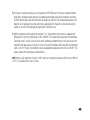
® HTUPS 3700 Home Theater Uninterruptible Power Supply PowerCenter Owner’s Manual ™ Table of Contents Page Important Safety Instructions . . . . . . . . . . . . . . . . . . . . . . . . . . . . . . . . . . . . . . . . . . . . . . . . . . . . . . . . . . . . . . . . . . . . i Proper Grounding and Instructions . . . . . . . . . . . . . . . . . . . . . . . . . . . . . . . . . . . . . . . . . . . . . . . . . . . . . . . . . . . . . . . iv A Note from The Head Monster . . . . . . . . . . . . . . . . . . . . . . . . . . . . . . . . . . . . . . . . . . . . . . . . . . . . . . . . . . . . . . . . . . 1 Monster® HD Clean Power® Filtering . . . . . . . . . . . . . . . . . . . . . . . . . . . . . . . . . . . . . . . . . . . . . . . . . . . . . . . . . . . . . . 2 Monster Exclusive T2™ Technology . . . . . . . . . . . . . . . . . . . . . . . . . . . . . . . . . . . . . . . . . . . . . . . . . . . . . . . . . . . . . . . . 3 Automatic Voltage Regulation . . . . . . . . . . . . . . . . . . . . . . . . . . . . . . . . . . . . . . . . . . . . . . . . . . . . . . . . . . . . . . . . . . . 4 Monster GreenPower ™ Outlet Management . . . . . . . . . . . . . . . . . . . . . . . . . . . . . . . . . . . . . . . . . . . . . . . . . . . . . . . . 4 Monster Countdown Technology . . . . . . . . . . . . . . . . . . . . . . . . . . . . . . . . . . . . . . . . . . . . . . . . . . . . . . . . . . . . . . . . . 5 The Minds Behind Monster Power . . . . . . . . . . . . . . . . . . . . . . . . . . . . . . . . . . . . . . . . . . . . . . . . . . . . . . . . . . . . . . . . 6 Monster HTUPS 3700 Features . . . . . . . . . . . . . . . . . . . . . . . . . . . . . . . . . . . . . . . . . . . . . . . . . . . . . . . . . . . . . . . . . . 7 Hookup and Operation Guide . . . . . . . . . . . . . . . . . . . . . . . . . . . . . . . . . . . . . . . . . . . . . . . . . . . . . . . . . . . . . . . . . . 12 Battery Connection and Replacement . . . . . . . . . . . . . . . . . . . . . . . . . . . . . . . . . . . . . . . . . . . . . . . . . . . . . . . . . 14 Power Hookup . . . . . . . . . . . . . . . . . . . . . . . . . . . . . . . . . . . . . . . . . . . . . . . . . . . . . . . . . . . . . . . . . . . . . . . . . 16 Coaxial Connections . . . . . . . . . . . . . . . . . . . . . . . . . . . . . . . . . . . . . . . . . . . . . . . . . . . . . . . . . . . . . . . . . . . . . 17 Phone Connections . . . . . . . . . . . . . . . . . . . . . . . . . . . . . . . . . . . . . . . . . . . . . . . . . . . . . . . . . . . . . . . . . . . . . . 18 Network Connections . . . . . . . . . . . . . . . . . . . . . . . . . . . . . . . . . . . . . . . . . . . . . . . . . . . . . . . . . . . . . . . . . . . . 19 Rack Mount Installation . . . . . . . . . . . . . . . . . . . . . . . . . . . . . . . . . . . . . . . . . . . . . . . . . . . . . . . . . . . . . . . . . . 20 Storage Instructions . . . . . . . . . . . . . . . . . . . . . . . . . . . . . . . . . . . . . . . . . . . . . . . . . . . . . . . . . . . . . . . . . . . . . . 21 Troubleshooting . . . . . . . . . . . . . . . . . . . . . . . . . . . . . . . . . . . . . . . . . . . . . . . . . . . . . . . . . . . . . . . . . . . . . . . . . . . . 22 Specifications . . . . . . . . . . . . . . . . . . . . . . . . . . . . . . . . . . . . . . . . . . . . . . . . . . . . . . . . . . . . . . . . . . . . . . . . . . . . . . 26 RS-232 Communications Protocol and Command Set . . . . . . . . . . . . . . . . . . . . . . . . . . . . . . . . . . . . . . . . . . . . . . . . 29 Warranty Information . . . . . . . . . . . . . . . . . . . . . . . . . . . . . . . . . . . . . . . . . . . . . . . . . . . . . . . . . . . . . . . . . . . . . . . . 47 IMPORTANT SAFETY INSTRUCTIONS This manual contains important instructions for the HTUPS 3700 that should be followed. Please read and observe the following safety points at all times. CAUTION: When the On/Off switch is on, the Battery Power supplied outlets are powered by the battery, even when the unit is not plugged in. CAUTION: To reduce the risk of electric shock, use only indoors and in dry locations. Do not allow the device to be exposed to moisture, rain, dust, excessive heat or direct sunlight. CAUTION: Connect this device to a 3-prong grounded outlet. Make sure the circuit branch is protected and not servicing equipment that requires heavy electricity. CAUTION: Never plug the device into itself; this will short-circuit the unit. CAUTION: This device may be damaged if connected to a motor-powered AC generator with voltage and frequency output beyond nominal accepted ranges. CAUTION: Risk of Electrical Shock! The battery circuit is not isolated from AC input. Hazardous voltage may exist between the terminal and ground. Disconnect the power cord from the wall outlet before servicing the battery. CAUTION: The output of this device is not sinusoidal when in UPS mode. Use with home theater equipment only. i WARNING – The battery in this product contains chemicals, including lead, known to the State of California to cause cancer and birth defects and other reproductive harm. Wash Hands after handling. Important Note: Charge the internal battery for 4 hours before using this HTUPS 3700 for the first time, or if it has not been plugged into an AC outlet for an extended period. WARNING – Power Sources Do not plug this HTUPS 3700 into a power outlet that differs from the source indicated for safe use on the HTUPS 3700. If you don’t know the type of electrical power that is supplied to your home, consult your local power company or a qualified electrician. WARNING – Grounding and Polarization A. Do not attempt to defeat the grounding feature by using a 3-to-2 prong adapter. B. The Monster HTUPS 3700 requires a properly grounded outlet for safety and to protect connected equipment. If you’re not sure if your home’s electrical wiring is properly grounded, have it checked by a qualified electrician. C. Do not force the HTUPS 3700 plug into a power outlet that is not designed to accept a three-wire grounded-type AC plug (a three-prong plug). This plug is designed to be inserted into a grounded-type outlet only. If this plug doesn’t fit directly inside the outlet, do not attempt to force it into the outlet. Never attempt to dismantle the plug in any way (or to alter the power cord). If you have questions about grounding, consult your local power company or a qualified electrician. CAUTION – Heat Ventilation HTUPS 3700 requires a minimum of 1” clearance on all sides for adequate ventilation and heat dissipation. WARNING – Medical Conditions/Life Support Applications ii Use of the HTUPS 3700 in any life support application where failure of this equipment can reasonably be expected to cause the failure of the life support equipment or to significantly affect its safety or effectiveness is NOT recommended. WARNING – Malfunction and Servicing If, for any reason, this HTUPS 3700 is not operating properly, unplug the unit and consult the Warranty Information section in this manual for important details, or contact your original retailer for repair and service information. WARNING – Power Cord Safety A. When routing the AC power cord, do not place it near areas with heavy foot traffic that would create a trip hazard (e.g., hallways, doorways, and floors). B. If the power cord’s protective jacket begins to rip or fray, exposing the internal wiring, shielding, etc., disconnect it from the power source and discontinue use of the HTUPS 3700 immediately. See the Warranty Information section in this manual for important details. WARNING – De-Energizing The HTUPS 3700 To fully de-energize the HTUPS 3700, unplug the unit from the wall outlet, then turn the unit off. CAUTION – Exposure to Heat Do not expose the HTUPS 3700 to direct sunlight or place it near wall heaters, space heaters, or any enclosed space prone to temperature increase. CAUTION – Proper Cleaning In general, the only cleaning necessary for this HTUPS 3700 is a light dusting. Unplug the component from the wall before cleaning it. Do not use any type of liquid or aerosol cleaners. FCC REQUIREMENTS NOTE: This equipment has been tested and found to comply with the limits for a Class B digital device, pursuant to part 15 of the FCC Rules. These limits are designed to provide reasonable protection against harmful interference in a residential installation. This equipment generates, uses and can radiate radio frequency energy and, if not installed and used in accordance with the instructions, may cause harmful interference to radio communications. However, there is no guarantee that interference will not occur in a particular installation. If this equipment does cause harmful interference to radio or television reception, which can be determined by turning the equipment off and on, the user is encouraged to try to correct the interference by one or more of the following measures: • Reorient or relocate the receiving antenna • Increase the separation between the equipment and receiver • Connect the equipment into an outlet on a circuit different from that to which the receiver is connected • Consult the dealer or an experienced radio/TV technician for help. iii proper grounding INSTRUCTIONS WARNING – Proper Grounding Monster PowerCenters require a properly grounded outlet for safety and to protect connected equipment. If you’re not sure if your home’s electrical wiring is grounded, have it checked by a qualified electrician. Important Note: Proper Power and Protection To completely protect your equipment against power surges, every AC cable, coaxial cable, phone line and Ethernet line in the system must be connected to an appropriate PowerCenter. Important Note: Proper Protection and the Limited Connected Equipment Warranty The $500,000 U.S. Limited Connected Equipment Warranty becomes invalid if any wire (AC, coax or phone) or audio or video interconnect leading into the equipment comes from a component that is not properly protected by the PowerCenter. See the warranty information section of this manual for important details. iv A NOTE FROM THE HEAD MONSTER THANK YOU for purchasing the Monster Power Home Theater Uninterruptible Power Supply 3700. The HTUPS 3700 is designed to maintain power to critical home theater components during power outages for up to 4 hours* with an internal backup battery. This lets your DVR record scheduled shows, preserves home theater settings, prevents data corruption on media servers, and prevents costly projector bulb damage. ® The HTUPS 3700 also incorporates Monster’s patented HD Clean Power filters, which are specifically engineered for today’s digital high definition components. This advanced technology reduces stress on delicate digital circuitry, delivering improved performance and maximizing the lifespan of connected equipment. Noel Lee Monster’s advanced surge protection technology features patented Tri-Mode that automatically disconnects equipment from both live power lines (line and neutral) and sounds an alarm. Microprocessor-controlled T2 works with Tri-Mode circuitry to automatically disconnect both the PowerCenter itself and your equipment from damaging surges and spikes. The HTUPS 3700 also features automatic voltage regulation, which keeps the voltage going to your home theater within a safe range. To save you energy and money, the HTUPS 3700 includes Monster GreenPower switched outlets that automatically shut off when you’re not using the equipment connected to them. This stops energy waste caused by HDTVs, Blu-ray Disc players and other components in stand-by mode. ™ ™ I’m sure you’ll enjoy the advanced protection, enhanced home theater performance, energy savings and backup power reassurance the HTUPS 3700 provides. Noel Lee, The Head Monster 1 *At 50 W consumption. Actual runtime depends on load, charge level, and battery condition. PATENTED MONSTER HD CLEAN POWER® filtering Your home’s electricity is full of noise and interference caused by all of your appliances and electronics: cell phones, computers, even your lights, all contribute to the problem. This “dirty power” stresses the delicate digital circuitry inside HDTVs and other home theater equipment, reducing their performance and potentially shortening their lives. However, ordinary surge protectors can’t remove the effects of dirty power. The HTUPS 3700 features HD Clean Power Stage 3 filtering that is precision-engineered to remove electrical noise and interference. This protects the delicate circuitry inside your HDTV and other electronics from unnecessary wear. HD Clean Power maximizes your equipment’s lifespan and ensures the best possible picture and sound performance. ™ Actual spectrum analyzer photo of AC power pollution AC power line filtered by Monster Clean Power ® To learn more about patented Monster Clean Power and the complete product family of PowerCenters, voltage stabilizers and amplifiers, please visit MonsterPower.com. 2 PATENTED MONSTER T2™ TECHNOLOGY The Monster Power HTUPS 3700 features exclusive Monster T2 technology. T2 is an active electronic microprocessorcontrolled circuit that sits in front of the surge protection circuitry in select Monster Power products. T2 monitors the line, neutral and ground lines and automatically disconnects the HTUPS 3700 from the AC power line when a long duration low-voltage sag or high-voltage swell occurs (continuous voltage below 80Vrms or above 132Vrms). Unlike ordinary power management devices, T2 will disconnect the HTUPS 3700 before the MOVs (Metal OxideVaristors) and thermal fuses sense an overload condition and sacrifice themselves to protect your connected components. This will extend the PowerCenter’s life, while providing the system protection you need. ™ 3 Monster Automatic Voltage Regulation Your home theater electronics are engineered to operate at 120 volts. But common power sags and swells can severely affect the performance and life of your valuable audio and video equipment. When this occurs, Monster automatic voltage regulation keeps the voltage going to your home theater within a safe range. This reduces wear on delicate circuitry, extending the life of your home theater components. ™ Monster GREENPOWER™ OUTLET MANAGEMENT Monster GreenPower is a revolutionary new way to automatically eliminate energy waste and save money. Simply plug your HDTV or AV receiver into the Monster GreenPower Control outlet. When it’s turned off or goes to sleep, the Monster GreenPower outlets switch off, automatically eliminating energy wasted by your subwoofer, DVD player, and more, when you’re not using them. When your HDTV or AV receiver switches back on, the GreenPower outlets automatically power up again. ™ 4 Monster Countdown Technology CHARGER B AT T E R Y % W AT TA G E CLEAN POWER ON UNSWITCHED ON SWITCHED/ TIMED ON UPS/AVR ON PROTECTION ON GROUND OK WIRING OK ABNORMAL VOLTAGE USB USB ON/OFF CH EC K V O LTA G E DIMMER LO ER A TT D BA Y O VE GREENPOWER STATUS AUX R HTUPS 3700 Home Theater Reference UPS with Clean Power ® Stage3 Filtering The Monster HTUPS 3700 features a digital LED display that displays remaining battery power time in minutes. You can instantly see how much time you have left to safely shut down your system, or how much time you can keep your system running. When power to the HTUPS is cut, the LED screen automatically switches from displaying voltage to the Countdown timer, which will begin counting backwards to zero. The Countdown start time will vary depending on how much battery capacity you have, the initial battery charge level, and the power consumption of equipment connected to the UPS. The Countdown timer actively measures current draw. As you turn on or off individual components in your system, the Countdown timer will dynamically adjust to reflect the backup time left. The more power consumed, the less time available, the less power being used, the more time available. Backup Time Testing You can test various system configurations to see how much backup time you’ll have when there’s a power outage. First, fully charge the HTUPS 3700,* and plug all your equipment into the HTUPS 3700. Refer to the setup instructions on pages 9-10. Then unplug the HTUPS 3700 from the wall outlet so it’s running purely on battery power. The HTUPS 3700 Countdown timer will activate displaying backup time. You may want to try testing with different components into the UPS outlets to gain more backup time. *Charge the battery for at least 4 hours to reach full charge capacity. 5 The Minds Behind MONSTER POWER Richard Marsh – Richard developed Monster’s patented Clean Power ® circuitry, and is also responsible for several other ground breaking designs including the high-end audio balanced circuit design, the MultiCap internal bypass capacitor, and the Servo-DC feedback concept in power amplifiers – a concept that is used by virtually every amplifier manufacturer today. Demian Martin – Demian helped create several innovative AC power solutions. He was the co-founder of Spectral Audio and was the chief designer of their many pioneering designs for amplifiers, D/A converters, and other high-end audio designs. He now brings his expertise to Monster Power’s elite research and development team. 6 Noel Lee – Noel Lee, The Head Monster, is best known for popularizing the concept of high performance audio cable 30 years ago with his creation of Monster Cable. Originally a laser-fusion design engineer at Lawrence Livermore National Laboratory and later a touring musician, Noel has invented or co-invented over 250 U.S. and international patents. Monster Power is Noel’s realization of a long-nurtured vision of making affordable power solutions that deliver the best possible sound and picture. Tony DiChiro was one of the founders of Kinergetics Research in 1971. Kinergetics developed numerous patented technologies that advanced the state of the art in audio technology, and released highly acclaimed home theater products. Kinergetics also debuted the first high-end surround sound processor with THX certification. Tony currently heads up the R&D team at Monster Cable where he continues to develop advanced products with cutting edge features. GRE HDTV/ TV RS 232 SWITCHED DC REMOTE IN TIMED GROUND SAT 2 OUT Designed in U.S.A. Manufactured in China MONSTER HTUPS 3700 FEATURES FRONT VIEW 1 2 3 5 4 6 7 8 CHARGER B AT T E R Y % W AT TA G E CLEAN POWER ON UNSWITCHED ON SWITCHED/ TIMED ON UPS/AVR ON PROTECTION ON GROUND OK WIRING OK ABNORMAL VOLTAGE USB USB ON/OFF GREENPOWER STATUS CH EC K LO ER AUX A TT D BA Y V O LTA G E O VE R HTUPS 3700 DIMMER 9 10 11 13 12 Home Theater Reference UPS with Clean Power ® Stage 3 Filtering 14 15 17 16 REAR VIEW 20 GREENPOWER CONTROLLED HIGH DEFINITION DIGITAL FILTER ANALOG AUDIO FILTER UNSWITCHED GAME CONSOLE OUT CABLE/ANT IN PLC COMPATIBLE GREENPOWER CONTROL IN 24 PHONE IN OUT 1 OUT BREAKER 12A PRESS TO RESET OUT 2 25 SAT 1 PROJECTOR SWITCHED 23 GREENPOWER CONTROL ON/OFF HIGH CURRENT FILTER ACCESSORY HDTV/ TV 22 MAIN AMP EXTERNAL BATTERY CONNECTOR RS 232 BATTERY/AVR ENABLED OUTLETS DVR/TIVO® SNMP CARD CABLE /SAT DVD/Blu-ray™ BATTERY/AVR ENABLED OUTLETS 21 MEDIA CENTER 19 RECEIVER 18 IN IN TIMED NETWORK DC REMOTE OUT IN OUT 120 V/12 AMP GROUND SAT 2 OUT Designed in U.S.A. Manufactured in China 7 26 27 28 29 30 31 32 33 HTUPS 3700 FEATURES FRONT 1.“Clean Power On” Indicator 2. “Unswitched On” Indicator 3.“Switched/Timed On” Indicator 4.“UPS/AVR On” Indicator 5.Battery % LED Bar 6.Alarm On/Off – GreenPower Status 7.Power On/Off 8.USB Charging Ports 9.“Protection On” Indicator 10. “Ground OK” Indicator 11. “Wiring OK” Indicator 12. “Abnormal Voltage” Indicator 13. Battery Check Indicator 14. Dimmer 15.Overload Indicator 16.Digital/Analog Display (Load Wattage, Output Voltage, Battery Remaining Time) 17.Switched Digital AC Output REAR 18. SMNP Card Port 19. GreenPower Switched HD Digital Outlets (with battery backup) 20. Switched Analog Outlet (with battery backup) 21. Timed High Current Outlet (PLC Compatible) 22. Monster GreenPower™ Control On/Off Switch 23. CATV/Antenna Surge Supression 24.Resettable 12Amp Circuit Breaker 25. IEC Power Cord Connection 26. RS232 Port 27. External Battery Connection* 28. GreenPower Control HD Digital Outlets (Master) 29. Phone Line Surge Suppression 30. “DC” In/Out Control 31. Network/Ethernet Surge Suppression 32. Satellite Surge Suppression 33. Ground Terminal 2 *You can extend your HTUPS 3700 battery runtime up to 12 hours** with the addition of the Monster Home Theater Extended Battery Supply HTBX3000. See your Monster retailer for details or go to MonsterCable.com. **at 50W consumption. Actual runtime depends on load, charge level, and battery condition. 8 Front Panel LED STATUS LIGHTS LED Function Visual Status CLEAN POWER ON Blue light flashes 16 times in 8 seconds when AC is plugged in On indicates that Clean Power filtering is on. PROTECTION ON Green light - On indicates that surge protection in On. UNSWITCHED ON Green light - On indicates that unswitched outlets are On. GROUND ON Green light - On indicates that HTUPS 3700 is properly grounded. WIRING OK Green light - On indicates that wiring is correct. UPS/AVR ON Green light - On indicates that battery backup and automatic voltage regulation are On. ABNORMAL VOLTAGE Red light is on when input voltage range is out of range (> 90 Vac or <129Vac) and flashes when in battery mode. Red light is off when input voltage range is normal. SWITCHED/TIMED ON LED Indicates that switched/timed outlets are On or Off. BATTERY CHECK LED When lit, it indicates the battery needs to be replaced. OVERLOAD LED • AC Mode – An overload has occurred. Unplug or turn off one or more of the devices plugged into the UPS/AVR outlets until the LED is off. • DC Mode – Overload LED and continuous Alarm sounds for few seconds and iwillshut down automatically. Reduce load and Press and hold ON/OFF button for 3 seconds to turn Unit back on. DIGITAL DISPLAY ALPHANUMERIC LED Displays Wattage, Output voltage, Battery Time Remaining, and GreenPower Status. WIRING OK LED Indicates your home wiring is correct or not. If not lit, contact a qualified electrician to check your home wiring. 9 BATTERY LED STATUS LIGHTS con’t In addition to the countdown meter, the HTUPS 3700 also features battery LED status lights. These lights indicate how much battery power has been expended and how much is left. BATTERY Capacity Bar 0% LED 25% LED 100% Fully Charged 10 75% LED 100% LED Green Flashing Off Green On 75% Charging 50% Charging 50% LED Green On Green On 25% Charging Orange On 0% Charging Red Flashing Green Flashing Off Orange Flashing Off Off Front Panel Buttons In addition to the countdown meter, the HTUPS 3700 also features battery LED status lights. These lights indicate how much battery power has been expended and how much is left. Button Function ALARM/GREENPOWER STATUS BUTTON Press and release to turn Off/On the alarm. Press and hold for 3 seconds to see current GreenPower status. POWER ON/OFF BUTTON • AC Mode – Press an release to turn switched/timed outlets On/Off. Also turn on the DC out trigger. • AC Mode – [Hard shutdown] To turn off all outlets including Unswitched outlets, press and hold the On/Off button for 10 sec. To turn back on, press On/Off for 1 second. • UPS Mode - Press and release to turn the switched/timed outlet On/Off. DC out trigger will not turn operate in UPS mode. • UPS Mode – Turn Unit off completely by holding the On/Off button for 3 seconds. To turn back on, press On/Off for 1 second. • UPS Mode Overload – Press and hold On/Off button 3 seconds to turn On the Unit after reducing the load. DIMMER BUTTON Press and hold to dim/brighten LED displays. 11 HookUp And Operation Instructions NOTE: The HTUPS 3700 must be plugged into a properly grounded, three-prong AC power outlet. In addition, Monster recommends charging the batteries for at least four hours prior to using HTUPS 3700. To charge or recharge the batteries, simply plug your HTUPS 3700 into an AC outlet. Powering Your HTUPS 3700 and Connected Equipment A)For safety reasons, the HTUPS 3700 ships with the battery disconnected. You must first manually connect the battery. See p.10 for instructions. B)Plug your AV equipment you would like to protect from power loss into the surge-protected, battery backup-supplied outlets. C)Plug the HTUPS 3700 into a properly grounded AC outlet. Always keep the HTUPS 3700 plugged into a live outlet to ensure the battery is charged. The HTUPS 3700 will then perform a self-test function. The “Clean Power On” LED will flash 16 times in 8 seconds and the unswitched outlet will be delayed 8 seconds to output power. The Clean Power On, Protection On, Unswitched On, UPS/AVR, Ground OK, and Wiring OK LEDs will illuminate steadily. The voltage and wattage meters will display input AC voltage level, and the battery runtime LED bar will display current battery capacity. D)Turn on your HTUPS 3700 switched outlets by pressing the Power On button. The Clean Power On, Protection On, Unswitched On, Ground OK, Switched/Timed On, Wiring OK and UPS/AVR On LEDs will illuminate steadily and the voltage meter will display input AC voltage level and the battery runtime LED bar will display current battery capacity, confirming that there is adequate power to the connected loads. 12 E)In the event of a utility power failure, you can still operate your HTUPS 3700, even if the unit was turned off during the power failure. Only battery backup outlets are still powered by battery during a power failure. Under back-up operation, the HTUPS 3700 will beep slowly and the LED meter will display how much time is left for battery backup power. In UPS mode, the unit will beep every five seconds, when there is approximately 25% charge left, it will beep twice every five seconds. You can turn off the beeping by pressing the Alarm On/Off button once. F) When the GreenPower switch located on the rear panel is “On,” the GreenPower Control function is enabled and the alphanumeric LED on the front panel display will show “GRN ON” for 5 seconds. When output power of the GreenPower Control HDD outlet is over 45w, it will turn on the other 3 GreenPower switched HDD outlets. If the output power of the master HDD outlet drops down less than 25w, it will turn off the other 3 GreenPower HDD outlets. When the GreenPower switch is in the “Off” position, the GreenPower Control is disabled and the alphanumeric LED will show ”GRN OFF” for 5 seconds, and all 4 HDD outlets become unswitched outlets. NOTE: When you push and hold on the Alarm “On/Off” button for 3 seconds, the alphanumeric LED will show “GRN ON or OFF” for 5 seconds and then return to normal. 13 BATTERY CONNECTION AND REPLACEMENT INSTRUCTIONS For safety reasons, the HTUPS 3700 is shipped with the internal battery disconnected. The HTUPS 3700 will not operate until the internal battery is first connected. Follow these steps to connect or disconnect the battery. Step One: Remove the screws on the front panel. Step Two: Connect the battery to the internal wire of the HTUPS. Step Three: Re-install the front panel and screws. IMPORTANT: Before using the HTUPS 3700 for the first time, charge the battery for at least 4 hours to reach full charge capacity. Failure to do so may limit the runtime of the battery. 14 Battery Connector Replace Battery Step One: Remove the screws on the front panel and the front panel itself. Battery Connector Step Two: Remove the screw on the battery retaining bracket and bracket itself. Step Three: Disconnect the battery connector from the internal wire of the HTUPS. Step Four: Grasp the battery pull tab and pull the battery module out of the HTUPS. Step Five: Slide the new battery module into the HTUPS. Step Six: Re-install the battery retaining bracket and screws. Step Seven: Reconnect the battery connector to the internal wire of the HTUPS. Step Eight: Re-install the front panel and screws. Important: It is illegal in most states to dispose of batteries in household trash. Contact your local recycler. Before storing the HTUPS for an extended period of time, follow these maintenance recommendations to ensure proper operation after long-term storage. 15 HOOKUP AND OPERATION INSTRUCTIONS High Definition Digital, Analog Audio, Video and Ultra-High Current Outlet Hookup A)Attach a Monster Power identification label to each component’s power cord before you plug it into the appropriate color-coded outlet. B) Plug each component’s power cord into the corresponding outlet. ANALOG AUDIO FILTER CABLE/ANT PLC COMPATIBLE RECEIVER SWITCHED OUT IN IN OUT 1 OUT TIMED IN IN NETWORK DC REMOTE OUT IN OUT 120 V/12 AMP GROUND SAT 2 OUT Designed in U.S.A. Manufactured in China IMPORTANT NOTES 1. For components not listed, determine if they are analog audio, high-definition digital, or high-current audio components (such as power amplifiers), and use the corresponding outlet for best performance. 2. It does not harm analog audio, video, high-definition digital, or high-current audio components to be connected to outlets different from their type. However, for the best Clean Power™ performance, Monster recommends plugging components to their corresponding outlets. 3. The ultra-high current audio outlets are power line communication (PLC) compatible; PLC devices should only be plugged into these outlets. Power Line Communication is a home networking solution that uses your home’s AC power wiring for data transfer. CHARGER B AT T E R Y % W AT TA G E USB USB 16 CLEAN POWER ON UNSWITCHED ON SWITCHED/ TIMED ON UPS/AVR ON PROTECTION ON GROUND OK WIRING OK ABNORMAL VOLTAGE BA TT D ON/OFF ER A BREAKER 12A PRESS TO RESET OUT 2 SAT 1 PROJECTOR UNSWITCHED GAME CONSOLE GREENPOWER CONTROL HDTV/TV RS 232 IN PHONE ACCESSORY EXTERNAL BATTERY CONNECTOR BATTERY/AVR ENABLED OUTLETS DVR/TIVO® SNMP CARD MAIN AMP CABLE/ SAT DVD/Blu-ray™ BATTERY/AVR ENABLED OUTLETS GREENPOWER CONTROL ON/OFF HIGH CURRENT FILTER MEDIA CENTER GREENPOWER CONTROLLED HIGH DEFINITION DIGITAL FILTER GREENPOWER STATUS AUX HOOKUP AND OPERATION INSTRUCTIONS Coaxial Connections Hookup Coaxial Connections provide surge protection against damaging voltage surges and spikes on the incoming cable, satellite and antenna lines. Protect TV/Cable, Satellite and Antenna Connections as Follows: R IN OUT From TV/Cable or Antenna MAIN AMP To TV/Cable Box or TV PHONE CABLE/ANT IN PLC COMPATIBLE TLETS GREENPOWER CONTROL ON/OFF HIGH CURRENT FILTER IN OUT 1 From Satellite Dish OUT OUT 2 BREAKER 12A PRESS TO RESET To Satellite Receiver or TV SAT 1 ACCESSORY IN NETWORK OUT IN OUT 120 V/12 AMP From Satellite Dish TIMED IN DC REMOTE To Satellite Receiver or TV OUT SAT 2 GROUND Designed in U.S.A. Manufactured in China 17 HOOKUP AND OPERATION INSTRUCTIONS Phone Connections Hookup Phone connections provide surge protection against damaging voltage surges and spikes coming from the phone line. This PowerCenter also incorporates a phone splitter for convenience. ETS From Telephone Wall Jack GREENPOWER CONTROL ON/OFF Protect Phone Line Connections as Follows: IN MAIN AMP PLC COMPATIBLE HIGH CURRENT FILTER OUT To Satellite Receiver, Digital Video Recorder (DVR), or Telephone PHONE CABLE/ANT IN IN IN OUT PHONE OUT 1 IN IN OUT PHONE OUT 2 OUT BREAKER 12A PRESS TO RESET OUT PHONE NOTE:The HTUPS 3700 is not intended for hookup of two separate phone lines on a single 4-pin RJ11 jack. SAT 1 ACCESSORY 18 TIMED IN IN NETWORK DC REMOTE OUT IN OUT 120 V/12 AMP OUT SAT 2 GROUND Designed in U.S.A. Manufactured in Ch HOOKUP AND OPERATION INSTRUCTIONS Network Connection Hookup Network (Ethernet RJ45) connections provide surge protection against damaging voltage surges and spikes coming from the Internet network line or local area network (LAN). Protect Network Connections as Follows: NETWORK From Local Area Network, DSL/Cable Modem, or Satellite Receiver To DVR, Satellite Receiver, or Computer/Media Server IN OUT 19 RACK MOUNTING INSTRUCTIONS Your HTUPS 3700 comes with front and rear rack mount ears for secure installation in AV rack systems. You will need a hex wrench (not included) to tighten the included bolts. Front Ear Installation Make sure the ears are correctly oriented as shown in the diagram at right. The curved edge should be oriented closer to the center of the HTUPS 3700. 20 Rear Ear Installation Install the rear ears as shown. Use more bolts for extra security. HTUPS 3700 STORAGE INSTRUCTIONS Before storing the HTUPS 3700 for an extended period of time, follow these maintenance recommendations to ensure proper operation after long-term storage. Charge the HTUPS 3700 for at least 4 hours before initial storage. Store the HTUPS 3700 covered and upright in a cool, dry location. During storage, recharge the battery in accordance with the following: Storage Temperature Recharge Frequency Charge Duration -15 to 30 Celsius (5-86 Fahrenheit) every 6 months 4 hours 30 to 45 Celsius (86-113 Fahrenheit) every 3 months 4 hours 21 Troubleshooting Symptom Possible Cause Remedy Component is not receiving power. The component is plugged into a switched outlet and the HTUPS 3700 has not been turned On. • Turn the HTUPS 3700 On. Speakers emit a humming or buzzing noise. 22 • Or, plug the component into an Unswitched outlet. The HTUPS 3700 is plugged into a Switched outlet, but power on the component is not On. In some instances, a component plugged into a switched outlet won’t receive power when the HTUPS 3700 is turned On unless the component power is also switched On. • Turn the component power On. The HTUPS 3700 is sharing AC power with equipment that is not properly grounded. • Connect your HTUPS 3700 to a dedicated outlet. • Try unplugging different components from the HTUPS 3700 one at a time to see if the noise stops. If a component is discovered to be improperly grounded, attach a copper wire from the component’s chassis to the HTUPS 3700’s grounding post. Troubleshooting con’t Symptom Possible Cause Remedy Video picture has rolling bars or ghosting. The incoming video signal is not properly grounded. • Ensure that the cable TV line is connected to the cable coax connection, not the Satellite coax connection. The ground loop isolation on the cable connection may interfere with satellite TV signals. • Contact your cable or satellite provider to correct your installation. The HTUPS 3700 is emitting a loud buzzing alarm. The HTUPS 3700 protection circuitry has sacrificed itself to protect connected equipment from a catastrophic surge. • The HTUPS 3700 must be replaced. See the Warranty Information section for important details. 23 Troubleshooting con’t Symptom Possible Cause Remedy HTUPS 3700 is not providing power. HTUPS 3700 is not turned on. • Make sure HTUPS 3700’s AC power plug is plugged into a properly grounded 120V wall outlet. Unit should turn on right away. • In some situations, a wall switch may need to be turned on to send electricity to the wall outlet. Try turning on the light switches located near the wall outlet powering HTUPS 3700. Battery voltage is low. • Verify that the internal battery connection is secure. (See Instructions on page 11) • Recharge HTUPS 3700’s battery for at least 4 hours. (Contact your Monster Power dealer if battery does not charge.) HTUPS 3700 is defective. • Please see warranty information. Too many devices are • Press the HTUPS 3700 Thermal Circuit Breaker button in to reset. connected, causing an Allow 10 minutes before attempting to reset. If you reset too overload, tripping the soon, the breaker will prematurely sense power overload Thermal Circuit Breaker. and prevent the PowerCenter from operating. 24 Troubleshooting con’t Symptom Possible Cause Remedy HTUPS 3700 is always in battery mode. Power cord is loose. • Ensure that the power cord is firmly plugged into the back of the unit and the AC wall outlet. HTUPS 3700 is defective. • Please see warranty information. The battery is not fully charged. • Recharge HTUPS 3700’s batteries for at least 4 hours. HTUPS 3700 is defective or home theater system total draw is higher than 900W. • Please see warranty information. An overload condition is occurring. • Unplug or turn off one or more of the devices plugged into the UPS/ AVR outlets until the alarm stops. Backup time is too short. Alarm beeps continuously. • Make sure the total system for backup is less than 900W. NOTE: It is normal for HTUPS 3700 to feel hot to the touch during normal or back-up operation. 25 Specifications Category Requirement Input Nominal Input Voltage 120Vac Input Frequency 60Hz Input Connections IEC 60320 C14 Cord Length 6’ (1.8m) Input Voltage Range 80Vac~130Vac Maximum Input Current 12A Transfer Time 10ms Output Power Capacity 900W/1500VA Output 26 Value Max. Configurable Power 900W/1500VA Voltage Regulation V in = 80Vac~130Vac V out = 120Vac±8% Nominal Output Voltage 120Vac Nominal Efficiency at Full Load 95% Nominal Output Frequency 60Hz Waveform Type of Battery Mode Quasi sine wave Output Connections 11 x NEMA5-15R Specifications con’t Category Requirement Value Without External Battery Battery & Runtime Battery Type Typical Recharge Time Communication & Management Sealed Lead Acid Battery 8 hr. 12 hr. Typical Backup Time @900W 12 min. 28 min. @750W 14 min. 39 min. @600W 20 min. 53 min. @450W 34 min. 67 min. @125W 109 min. 305 min. @50W 320 min. 640 min. Control Panel DC Trigger Audible Alarm Surge Protection & Filtering With External Battery Surge Energy Rating Protection Modes Filtering LED display & Control Console 1 In 1 Out Audible & Visible Alarms 7480 Joules Line-Neutral (L-N), Line-Ground (L-G) Neutral-Ground (N-G) Meet UL1283 Phone Line Protection RJ11 1 In 2 Out Network line Protection RJ45 1 In 1 Out SAT/CATV Coax Coax 3 In 3 Out 27 Specifications con’t Category Requirement Physical Maximum Height 88mm (3.46”) Maximum Width 434mm (17.08”) 482.6mm (19”) w/ rack mounted bracket Maximum Depth 470mm (18.48”) Environmental Operating Environment Operating Relative Humidity 0 - 40°C (32-104°F) 5 - 95% Operating Elevation 0 - 3000m Storage Temperature -15 - 45°C (5-113°F) Storage Relative Humidity Storage Elevation 28 Value 5 - 95% 0 - 15000m RS-232 communications protocol and Command Set con’t 29 RS-232 communications protocol and Command Set con’t A. General : This document specifies the RS-232C communication protocol of the HTUPS3700. Computer will control information exchange by a query followed by < cr >. UPS will respond with information followed by a < cr > or action. B. Hardware: Data format BAUD RATE : 2400 bps DATA LENGTH : 8 bits STOP BIT : 1 bit PARITY : NONE Pin definition: COMPUTER UPS =================================== RX <---------- TX (pin 2) TX ----------> RX (pin 3) 30 GND <--------> GND (pin 5) RS-232 communications protocol and Command Set con’t C. Communication protocol All command and data are ASCII character 1. Turn On/Off beep -- Toggle the UPS beeper : Computer : Q<cr> When the AC power failed, UPS will generate a warning beep to inform the manager. Manager could toggle the warning beep by sending this command. 31 RS-232 communications protocol And Command Set con’t 4 2 UNSWITCHED SWITCHED IN IN OUT 1 OUT IN IN NETWORK DC REMOTE OUT IN OUT 120 V/12 AMP GROUND SAT 2 OUT Designed in U.S.A. Manufactured in China 5 0.GreenPower Control Outlet – When Green is Power Disabled, Use Outlet for Modem 1. GreenPower Switched Outlet 1 – When Green is Power Disabled, Use Outlet for Router 2.GreenPower Switched Outlets 2 – When Green is Power Disabled, Use Outlet for Network Device 3.Switched Outlets 1 and Serial Switched Outlet 4. Switched Outlets 2 and Serial Switched Outlet 5.Timed Outlets and Serial Switched Outlet CHARGER B AT T E R Y % W AT TA G E CLEAN POWER ON UNSWITCHED ON SWITCHED/ TIMED ON UPS/AVR ON PROTECTION ON GROUND OK WIRING OK ABNORMAL VOLTAGE USB USB ON/OFF CH EC K V O LTA G E DIMMER 32 LO ER A TT D BA Y O VE BREAKER 12A PRESS TO RESET OUT 2 SAT 1 TIMED 3 0 OUT CABLE/ANT PLC COMPATIBLE RECEIVER GAME CONSOLE HDTV/ TV RS 232 IN PHONE ACCESSORY GREENPOWER CONTROL BATTERY/AVR ENABLED OUTLETS DVR/TIVO® EXTERNAL BATTERY CONNECTOR MAIN AMP CABLE /SAT DVD/Blu-ray™ BATTERY/AVR ENABLED OUTLETS GREENPOWER CONTROL ON/OFF HIGH CURRENT FILTER MEDIA CENTER ANALOG AUDIO FILTER GREENPOWER CONTROLLED HIGH DEFINITION DIGITAL FILTER SNMP CARD 6 PROJECTOR 1 GREENPOWER STATUS AUX R HTUPS 3700 Home Theater Reference UPS with Clean Power ® Stage 3 Filtering RS-232 communications protocol and Command Set con’t 2. Turn on the bank <n> outlets : Computer : ON<n><cr> <n> is a number ranging from 0 to 6. 0 is the bank-0 ( Master outlet ) 1 is the bank-1 ( Slave-1 ) 2 is the bank-2 ( Slave-2 ) 3 is the bank-3 ( Switch-1 ) 4 is the bank-4 ( Switch-2 ) 5 is the bank-5 ( PLC outlets ) 6 is turned on all bank outlets. Slide switch Enable Disable 0 Bank-0 ( Master outlet ) Bank-0 (unswitch) 1 Bank-1 ( Slave-1 ) Bank-1 (unswitch) 2 Bank-2 ( Slave-2 ) Bank-2 (unswitch) 3 Bank-3 ( Switch-1 ) Bank-3 ( Switch-1 ) 4 Bank-4 ( Switch-2 ) Bank-4 ( Switch-2 ) 5 Bank-5 ( PLC outlets ) Bank-5 ( PLC outlets ) 6 Bank-3/4/5 Bank-0/1/2/3/4/5 33 RS-232 communications protocol and Command Set con’t For example: ON3 <cr> : UPS turn on the bank-3 outlets. Note: a. Master/Slave slide switch is enabled: The bank-0 outlet is master outlet. The slave outlets ( bank-1 and bank-2 ) turn on or off, they will depend on the master outlet output power. If the master outlet output power is over 45W, the slave outlets will be turned on. If the master outlet output less than 25W, the slave outlets will be turned off. The master outlet will be turned on after 8 seconds when UPS is plugged into utility power. UPS will not accept the “ON0<cr>”,”ON1<cr>”,“ON 2<cr>” and “R<cr>” commands. The monitor software will not send these commands to UPS. The “ON6<cr>” command only control the bank-3/4/5 outlets. b. Master/Slave slide switch is disabled: The bank-0, bank-1 and bank-2 outlets are defined to unswitched outlets. The unswitched outlets will be turned on after 8 seconds when UPS is plugged into utility power. Or the monitor software send the “ON0<cr>”, “ON1<cr>” and “ON2<cr>”, “ON3<cr>”, “ON4<cr>”, “ON5<cr>” to turn on the bank-0, bank-1, bank-2, bank-3, bank-4 and bank-5 outlets. The “ON6<cr>” command can turn on all the outlets ( bank-0/1/2/3/4/5 ). 34 RS-232 communications protocol and Command Set con’t 3. Turn off the bank<n> outlets : Computer : OF<n><cr> <n> is a number ranging from 0 to 6. 0 is the bank-0 ( Master outlet ) 1 is the bank-1 ( Slave-1 ) 2 is the bank-2 ( Slave-2 ) 3 is the bank-3 ( Switch-1 ) 4 is the bank-4 ( Switch-2 ) 5 is the bank-5 ( PLC outlets ) 6 is turned off all bank outlets. Slide switch Enable Disable 0 Bank-0 ( Master outlet ) Bank-0 (unswitch) 1 Bank-1 ( Slave-1 ) Bank-1 (unswitch) 2 Bank-2 ( Slave-2 ) Bank-2 (unswitch) 3 Bank-3 ( Switch-1 ) Bank-3 ( Switch-1 ) 4 Bank-4 ( Switch-2 ) Bank-4 ( Switch-2 ) 5 Bank-5 ( PLC outlets ) Bank-5 ( PLC outlets ) 6 Bank-3/4/5 Bank-0/1/2/3/4/5 35 RS-232 communications protocol and Command Set con’t For example: OF3<cr> : UPS will turn off the bank-3 outlets. Note: a. Master/Slave slide switch is enabled: The bank-0 outlet is master outlet. The slave outlets ( bank-1 and bank-2 ) turn on or off, they will depend on the master outlet output power. If the master outlet output power over 45W, the slave outlets will be turned on. If the master outlet output less than 25W, the slave outlets will be turned off. The master outlet will be turned on after 8 seconds when UPS is plugged into utility power. UPS will not accept the “OF0<cr>””OF1<cr>” and “OF 2<cr>” commands. The monitor software will not send these commands to UPS. The “OF6<cr>” command only control the bank-3/4/5 outlets. b. Master/Slave slide switch is disabled: The bank-0, bank-1 and bank-2 outlets are defined to unswitched outlets. The unswitched outlets will be turned on after 8 seconds when UPS is plugged into utility power. The monitor software can send the “OF0<cr>”, “OF1<cr>”, “OF2<cr>”, “OF3<cr>”, “OF4<cr>”and “OF5<cr>” to turn off the bank-0, bank-1, bank-2, bank-3, bank-4 and bank-5 outlets. 36 The “OF6<cr>” command can turn off all the outlets ( bank-0/1/2/3/4/5 ). RS-232 communications protocol and Command Set con’t 4. Status command : Computer : ST<cr> UPS : (III OOO CC.C WWWW BB.B b7b6b5b4b3b2b1b0<cr> a. Start byte : ( b. Input voltage : III III is an integer number ranging from 000 to 999. In this model, III is 120. The unit is “Volt”. c. Out voltage : OOO OOO is an integer number ranging from 000 to 999. In this model, OOO is 120. The unit is “Volt”. d. Output current : CC.C CC.C is an number ranging from 00.0 to 99.9. The unit is “Amp”. e. Output watts : WWWW WWWW is an integer number ranging from 0000 to 9999. The unit is “Watt”. 37 RS-232 communications protocol and Command Set con’t f. Battery voltage : BB.B BB.B is an number ranging from 00.0 to 99.9. The unit is “Voltage”. g. Outlet status: <b7b6b5b4b3b2b1b0>. “ bN” is an ASCII character ‘0’ or ‘1’. Bit Description 7 This bit is reserved to next function. The default value is 0. 6 1 : Bank-5 outlets are enable. 0 : Bank-5 outlets are disable. 5 1 : Bank-4 outlets are enable. 0 : Bank-4 outlets are disable. 4 1 : Bank-3 outlets are enable. 0 : Bank-3 outlets are disable. 3 1 : Bank-2 outlets are enable. 0 : Bank-2 outlets are disable. 2 1 : Bank-1 outlet is enable. 0 : Bank-1 outlet is disable. 1 1 : Bank-0 outlet is enable. 0 : Bank-0 outlet is disable. 0 1 : Master/Slave switch is enable. 0 : The switch is disable h. Stop byte : <cr> 38 RS-232 communications protocol and Command Set con’t For example : Computer : ST<cr> UPS : (120 120 05.0 0600 48.0 01111110<cr> Means : Input voltage is 120V. Output voltage is 120V. Output current is 5.0A Output watts is 600W. Battery voltage is 48.0 V 0 is Reserve bit. Default value is 0 Bank 5 is On Bank 4 is On Bank 3 is On Bank 2 is On Bank 1 is On Bank 0 is On The Master/Slave switch is disabled. 39 RS-232 communications protocol and Command Set con’t Computer : ST<cr> UPS : (110 121 02.0 0242 48.0 00110011<cr> Means : Input voltage is 110V. Output voltage is 121V. Output current is 2.0A Output watts is 242W. Battery voltage is 48.0 V The Master/Slave switch is enabled and the bank-0/3/4 are turned on, the bank-1/2/5 are off. 5. Reboot command : Computer : R<cr> a. When Master/Slave switch is Enable. UPS : The Master/Slave outlet will not be affected by the R command. b. When Master/Slave switch is Disable. 40 RS-232 communications protocol and Command Set con’t UPS : UPS will shutdown the bank-0 and bank-1. After 30 seconds UPS turn on the bank-0 outlet. After the bank-0 is on 20 seconds, the bank-1 will be turned on. Reboot command will have no effect on the bank-2/3/4/5 outlets, they will work in their normal function. Note: The function of the Master slave is defined in the DPS 6. Set Meter brightness : Computer : L<n><cr> UPS : The meter brightness is divided to 5 levels from 0 to 4. ‘0’ is dark and ‘4’ is fully light. This function is also controlled by Dimmer switch. L3<cr> : The meter brightness will be drove level 3. 41 RS-232 communications protocol and Command Set con’t 7.Enable Polled mode : Computer : PN<cr> UPS : #CCCC B MMMMMMMMMM V.V L<cr> UPS will continue reported the message until receive the “PF<cr>” command. a. Start byte : # b. Count down time: CCCC CCCC is an integer number ranging from 0000 to 9999. The unit is “Min”. c. Backup mode : B B is an ASCII character ‘0’ or ‘1’. ‘0’ is AC mode. 1’ is Backup mode. d. Model number : MMMMMMMMMM The 10 ASCII characters show the model name. For example : HTUPS-3700 42 RS-232 communications protocol and Command Set con’t e. Firmware version : V.V V is an integer number ranging from 0 to 9. For example : 1.1 ---> The firmware version is v1.1. h. Utility power fail: L ‘L’ is an ASCII character ‘0’ or ‘1’. ‘0’ means the utility power is out of 80~132Vac. ‘1’ means the utility power is normal. i. Stop byte : <cr> For example : Computer: PN<cr> UPS : #0110 1 HTUPS-3700 1.1 0<cr> Means : Count down time is 0110 minutes. UPS is backup mode. Model name is HTUPS-3700. The firmware version is 1.1. The utility power is out off 80~132Vac. Note : UPS auto report status every 1 second 43 RS-232 communications protocol and Command Set con’t 8. Disable Polled mode and return to Answer/Respond mode : Computer : PF<cr> UPS : PF<cr> UPS will stop polled mode and return to Answer/Respond mode. 9. If UPS receives the wrong command, UPS will respond @@@@@@@<cr>. Computer : AAA<cr> UPS : @@@@@@@<cr> UPS no action with wrong command format. 44 RS-232 communications protocol and Command Set con’t 10.Emergency Shutdown Command : WARNING The procedure will shut down the HTUPS completely. You must manually press the unit’s ON button to turn the HTUPS back on. Computer : S<nnnn><cr> UPS : Shut UPS output off in <nnnn> minutes. nnnn is an integer number ranging from 0000 to 9999. For example : Computer : S0010<cr> UPS will shutdown the output power after 10 minutes. 11. Cancel Shutdown Command : Computer : C<cr> UPS: Cancel the S<nnnn><cr> command. 45 RS-232 communications protocol Command Set con’t 46 LIMITED WARRANTY FOR CONSUMERS Monster, LLC, 7251 W Lake Mead Blvd, Las Vegas, NV, USA (“Monster”) extends to You this Limited Warranty. Statutory or common law may provide You with additional rights or remedies, which shall not be affected by this Limited Warranty. DEFINITIONS “Adequate Use” means use of the Product and Connected Equipment (i) within a home or dwelling, (ii) for private (as opposed to commercial) purposes, (iii) in conformance with all applicable local, state or federal law, code or regulations (including without limitation building and/or electrical codes), (iv) in accordance with manufacturer recommendations and/or instructions in the materials and documentation that accompany the Product and any Connected Equipment, (v) with proper electrical grounding, (vi) with proper and direct connection between the Product and an AC power source that has protective grounding (excluding gas or diesel powered generators), (vii) with cable or telephone lines to any Connected Equipment properly connected to the Product, and (viii) without a connection in a “daisy-chain” fashion to or with any extension cord, surge suppressor, power strip, uninterruptible power supply (“UPS”) or other equipment. “Authorized Dealer” means any distributor, reseller or retailer that (i) was duly authorized to do business in the jurisdiction where it sold the Product to You, (ii) was permitted to sell You the Product under the laws of the jurisdiction where You bought the Product, and (iii) sold You the Product new and in its original packaging. “Connected Equipment” means any device that is (i) generally suited to be used with the Product or products of the same kind, (ii) meets the requirements of all applicable laws and safety standards, (iii) contains only parts manufactured, sold or recommended by the original manufacturer of the Connected Equipment, and (iv) has not been altered, tampered with or modified by any person other than its manufacturer or service personnel authorized or recommended by the manufacturer of the Connected Equipment. 47 “Connected Equipment Damage” means physical damage caused to Connected Equipment due to a Product Defect (i) by a transient AC power, cable, telephone, or lightning surge while connected to a properly installed Product, (ii) not by a defect or unrelated damaging of the Connected Equipment or a surge/spike or lightning strike through a source, medium or connection other than through the Product, and (iii) does not extend to loss of data or consequential, indirect or special damages resulting from the Connected Equipment Damage. “Fair Market Value” (“FMV”) means the fair market value of the Connected Equipment at the time Connected Equipment Damage occurs. “Formal Warranty Claim” means a claim made in accordance with the section “Formal Warranty Claims” herein. “Maximum Coverage Amount” means the maximum amount that Monster will pay to You under this Limited Warranty for Connected Equipment Damages and is defined in relation to each Product in the Specifications Table below. “Product” means a Product (i) that is listed in the Specifications Table below, (ii) that You bought from an Authorized Dealer new and in its original packaging, and (iii) whose serial number, if any, has not been removed, altered, or defaced. “Product Defect” means a defect, malfunction, non-conformance to this Limited Warranty or other inadequacy of the Product that existed at the time when You received the Product from an Authorized Dealer and that causes a failure of the Product to perform in accordance with Monster’s documentation accompanying the Product, unless such failure has been caused completely or partly by (a) any use other than Adequate Use, (b) transportation, neglect, misuse or abuse by anyone other than Monster’s employees; (c) alteration, tampering or modification of the product by anyone other than a Monster employee; (d) accident (other than a malfunction that would otherwise qualify as a Product Defect); (e) maintenance or service of the Product by anyone other than a Monster employee; (f) exposure of the Product to heat, bright light, sun, liquids, sand or other contaminants; or (g) acts outside the control of Monster, including without limitation acts of God, fire, storms (excluding lightning surges), earthquake or flood. 48 “Warranty Period” means the time period during which Monster must have received Your Formal Warranty Claim. The different Warranty Periods related to Product Defects and Connected Equipment Damage are defined in the Specifications Table below. The Warranty Period commences on the date when You purchased or received (whichever occurs later) the Product from an Authorized Dealer as evidenced by the Authorized Dealer’s invoice, sales receipt or packing slip. If You do not have written proof of the date of purchase or receipt, then the Warranty Period commences three (3) months after the date when the Product left Monster’s factory as evidenced by Monster’s records. The Warranty Period ends after the time defined in the Specifications Table has expired, or after You have transferred ownership of the Product, whichever occurs earlier. Also, You must call Monster and obtain a Return Authorization Number (as described under “How to Make a Claim”) within two (2) months after You discover a Product Defect (or should have discovered it, if such Product Defect was obvious). “You” means the first individual person that purchased the Product in its original packaging from an Authorized Dealer. This Limited Warranty does not apply to persons or entities that bought the Product (i) in used or unpackaged form, (ii) for resale, lease or other commercial use, or (iii) from someone other than an Authorized Dealer. SCOPE OF THIS LIMITED WARRANTY PRODUCTS. If a Product contained a Product Defect when You bought it from an Authorized Dealer and Monster receives a Formal Warranty Claim from You within two (2) months after You discover such Product Defect (or should have discovered it, if such Product Defect was obvious) and before the end of the Warranty Period for Product Defects applicable to the affected Product, then Monster will provide You with one of the following remedies: Monster will (1) repair or, at Monster’s sole discretion, replace the Product, or (2) refund to You the purchase price You paid to the Authorized Dealer for the affected Product if repair or replacement is not commercially practicable or cannot be timely made. CONNECTED EQUIPMENT DAMAGE. Monster will also provide You with a remedy regarding Connected Equipment Damage if (i) You have a claim under the Limited Warranty for Products because of a Product Defect that causes Connected Equipment Damage despite Adequate Use, and (ii) Monster receives a Formal Warranty Claim from You before the end of the Warranty Period for Connected Equipment Damage applicable to the affected Product. If the conditions listed 49 in the preceding sentence are met, Monster will provide You with one of the following remedies provided that Monster may decide at its sole discretion which of the three remedies it provides: Monster will (1) replace the damaged Connected Equipment; (2) pay to repair the damaged Connected Equipment; or (3) pay You the FMV of the Connected Equipment, provided that such payments shall not exceed (i) the Maximum Coverage Amount for the Product, or (ii) the actual damage having arisen from power surges due to a Product Defect. NOTE: COMPENSATION FOR RESTORATION OF DATA LOSS IS NOT COVERED AND MONSTER DOES NOT ASSUME ANY LIABILITY FOR ANY INCIDENTAL, CONSEQUENTIAL OR INDIRECT DAMAGES UNDER THIS LIMITED WARRANTY. SOME STATES DO NOT ALLOW THE EXCLUSION OR LIMITATION OF INCIDENTAL OR CONSEQUENTIAL DAMAGES, SO THE ABOVE LIMITATION OR EXCLUSION MAY NOT APPLY TO YOU. GENERAL PROVISIONS CHOICE OF LAW/JURISDICTION. The laws of the State of California, USA, govern this warranty. It gives you specific legal rights, and you may also have other rights that vary from state to state. This warranty does not affect any additional rights you have under laws in your jurisdiction governing the sale of consumer goods, including, without limitation, national laws implementing EC Directive 44/99/EC. OTHER RIGHTS. THIS LIMITED WARRANTY GIVES YOU SPECIFIC LEGAL RIGHTS, AND YOU MAY ALSO HAVE OTHER RIGHTS, WHICH VARY FROM STATE TO STATE. THIS WARRANTY EXTENDS ONLY TO YOU AND CANNOT BE TRANSFERRED OR ASSIGNED. If any provision of this Limited Warranty is unlawful, void or unenforceable, that provision shall be deemed severable and shall not affect any remaining provisions. In case of any inconsistency between the English and other versions of this Limited Warranty, the English version shall prevail. REGISTRATION. Please register Your Product at MonsterPower.com. Failure to register will not diminish Your warranty rights. 50 SPECIFICATIONS TABLE Product Model No. HTUPS 3700 Warranty Period for Products 5 Years Warranty Period for Battery 2 Years Maximum Coverage Amount US$500,000 Warranty Period for Connected Equipment Damage 5 Years 51 FORMAL WARRANTY HOW TO MAKE A CLAIM. In the event damage has occurred to Products or Connected Equipment, You must follow these instructions: (1) Call Monster within two (2) months after You discover a Product Defect (or should have discovered it, if such Product Defect was obvious); (2) Give a detailed explanation of how the damage occurred; (3) Obtain a Return Authorization Number; (4) Upon receipt of a claim form (which may be sent to You after You filed Your Formal Warranty Claim), fill out the claim form entirely; (5) Return the Products, shipping prepaid by You (to be refunded if You are entitled to a remedy under the Scope of this Limited Warranty), to Monster for verification of damage, along with a copy of Your original sales receipts and proof of purchase (UPC label or packing slip) for such Products, the completed claim form, and printed Return Authorization Number on the outside of the return package (the claim form will include instructions for return). TELEPHONE NUMBERS. United States, Latin America and Asia Pacific: 1 877 800-8989 or 415-840-2000, Canada 1-866-348-4171, Czech Republic 800-14247, UK 0800 0569520, Germany 0800 1819388, France 0800 918201, Netherlands 0800 0228919, Belgium 0800 79201, Norway 800 10906, Denmark 8088 2128, Sweden 020 792650, Finland 800 112768, Greece 00800 35312008, Russia 810 80020051353, Italy 800 871479, Spain 900 982909. FURTHER PROCEEDINGS. Monster will determine whether a Product Defect existed and the damage to the Connected Equipment was caused by the Product. You must allow Monster access to the premises and site where the damage occurred and all equipment and property related thereto for Monster inspection by its employees or authorized representatives. Monster may, at its discretion, direct You to obtain a repair estimate at a service center or, proof of damage from an authorized dealer. If a repair estimate is required, You will be instructed on how to properly submit the estimate and the resulting invoice to Monster for payment. Any fees for repairs may be negotiated by Monster. TIMING. If You bring a Formal Warranty Claim and fully comply with all terms and conditions of this Limited Warranty, Monster will use its best efforts to provide You with a remedy within thirty (30) days after receipt of Your Formal Warranty Claim (if You reside in the United States - forty-five (45) days if You reside elsewhere), unless obstacles outside Monster’s control delay the process. 52 Vers 8/1/2006 – US/EU ©2009 Monster, LLC We invite you to visit the Monsters at: MonsterPower.com Designed in the USA and manufactured for Monster to its quality specifications. The Monster Power HTUPS 3700 is protected under U.S. Patent No. US 5,589,718; 6,473,510 B1; 6,683,770 B1; 6,614,636 B1; 6,829,129 B2; 7,262,945 B2; 5,589,718; 7,262,945 B2; TAIWAN NI-130119; N1-171813; N1-165023; CHINA ZL99107639.7. Other Patents Pending. ”Monster“, ”Monster Cable“, ”Monster Power“, ”Monster Clean Power“, ”PowerCenter“, ”PowerLine“, “the T2 logo”, the Monster Power logo, and “Tri-Mode” are trademarks or registered trademarks of Monster Cable Products, Inc. and its subsidiaries in the US and other Countries. © 2009 Monster, LLC 7251 West Lake Mead Blvd. Las Vegas, NV 89128, USA 1-877-800-8989 rm 195378