1
HP 7500 Switch Series
Installation Guide
5998-1730
Part number: 5998-1730a
Document version: 6W105-20141107
Legal and notice information
© Copyright 2014 Hewlett-Packard Development Company, L.P.
No part of this documentation may be reproduced or transmitted in any form or by any means without
prior written consent of Hewlett-Packard Development Company, L.P.
The information contained herein is subject to change without notice.
HEWLETT-PACKARD COMPANY MAKES NO WARRANTY OF ANY KIND WITH REGARD TO THIS
MATERIAL, INCLUDING, BUT NOT LIMITED TO, THE IMPLIED WARRANTIES OF MERCHANTABILITY
AND FITNESS FOR A PARTICULAR PURPOSE. Hewlett-Packard shall not be liable for errors contained
herein or for incidental or consequential damages in connection with the furnishing, performance, or
use of this material.
The only warranties for HP products and services are set forth in the express warranty statements
accompanying such products and services. Nothing herein should be construed as constituting an
additional warranty. HP shall not be liable for technical or editorial errors or omissions contained
herein.
Contents
Preparing for installation ············································································································································· 1 Safety recommendations ·················································································································································· 1 General safety recommendations ··························································································································· 1 Electricity safety ························································································································································ 1 Handling safety ························································································································································ 2 ESD prevention ························································································································································· 2 Laser safety································································································································································ 2 Examining the installation site ········································································································································· 2 Floor loading····························································································································································· 2 Temperature ······························································································································································ 3 Humidity ···································································································································································· 3 Cleanness ·································································································································································· 3 EMI ············································································································································································· 4 Grounding ································································································································································· 4 Power ········································································································································································· 4 Cooling ······································································································································································ 5 Space ········································································································································································· 6 Installation tools ································································································································································· 6 Installing the switch ······················································································································································ 8 Confirming installation preparations·······························································································································8 Attaching slide rails and cage nuts to the rack··············································································································9 Installing slide rails ··················································································································································· 9 Installing cage nuts ················································································································································ 12 Installing mounting brackets and cable management brackets········································································ 13 Mounting the switch to the rack···································································································································· 16 Grounding the switch ···················································································································································· 17 Grounding the switch with a grounding strip ····································································································· 17 Grounding the switch through the PE wire of an AC power supply ································································ 18 Grounding the switch through the RTN wire of a DC power supply ······························································· 18 Installing FRUs ···························································································································································· 20 Attaching an ESD wrist strap ········································································································································ 20 Installing a card······························································································································································ 21 Installing a power supply ·············································································································································· 22 Installing a power supply ····································································································································· 22 Connecting the power cord ································································································································· 23 Setting up a PoE system (optional) ······························································································································· 32 Requirements ·························································································································································· 32 Installing a PoE DIMM ·········································································································································· 33 Connecting an external PoE power supply ········································································································ 36 Installing a CF card to an MPU (optional) ··················································································································· 37 Installing a transceiver module (optional) ···················································································································· 38 Installing an XFP/SFP+/SFP/QSFP+ transceiver module ·················································································· 38 Installing a CFP module ········································································································································ 39 Connecting an SFP+/QSFP+/QSFP+ to SFP+ cable ························································································ 40 Setting up an IRF fabric ············································································································································· 41 IRF fabric setup flowchart ·············································································································································· 41 Planning IRF fabric setup ··············································································································································· 41 i
Planning IRF fabric size and the installation site ································································································ 41 Identifying the master switch and planning IRF member IDs ············································································ 42 Planning IRF topology and connections ·············································································································· 42 Identifying physical IRF ports on the member switches ····················································································· 42 Installing IRF member switches ····································································································································· 43 Configuring basic IRF settings······································································································································· 43 Connecting the physical IRF ports ································································································································ 43 Verifying the IRF fabric configuration ·························································································································· 44 Connecting your switch to the network ···················································································································· 45 Accessing the switch for the first time ·························································································································· 45 Setting up the configuration environment ··········································································································· 45 Setting terminal parameters·································································································································· 46 Powering on the switch ········································································································································· 49 Configuring the switch ··················································································································································· 50 Configuring authentication on a user interface ·································································································· 50 Configuring the basic access function ················································································································ 51 Configuration example ········································································································································· 51 Verifying the network configuration ···················································································································· 52 Connecting the switch to the network ·························································································································· 53 Connecting your switch to the network through twisted pair cables ······························································· 53 Connecting your switch to the network through optical fibers ········································································· 53 Testing connectivity ························································································································································ 54 Hardware management and maintenance ·············································································································· 55 Displaying information about the switch ····················································································································· 55 Displaying software and hardware version information ··················································································· 55 Displaying switch running information ················································································································ 57 Displaying detailed information about a card ··································································································· 58 Displaying electronic label data ·························································································································· 61 Displaying card CPU usage statistics ·················································································································· 62 Displaying card memory usage statistics ············································································································ 63 Displaying CF card information ··························································································································· 63 Displaying the operating status of the fan assembly ························································································· 64 Displaying the operating status of power supplies ···························································································· 64 Configuring the temperature thresholds for a card···························································································· 64 Port configuration and management···························································································································· 65 Configuring a combo interface ···························································································································· 65 Enabling active/standby mode for the network ports on MPUs ······································································ 66 Verifying and diagnosing transceiver modules ·········································································································· 67 Verifying transceiver modules ······························································································································ 67 Diagnosing transceiver modules ·························································································································· 67 Configuring a software exception handling method ·································································································· 68 Configuring an exception handling method······································································································· 68 Displaying the exception handling method ········································································································ 68 Displaying IRF information ············································································································································ 68 Displaying information about all IRF member switches ····················································································· 68 Displaying the basic IRF settings of IRF member switches················································································· 70 Displaying IRF topology information ··················································································································· 70 Saving the running configuration ································································································································· 71 Rebooting a card or the switch ···································································································································· 72 Troubleshooting ·························································································································································· 74 Troubleshooting methods··············································································································································· 74 Troubleshooting the system ··········································································································································· 74 Troubleshooting on startup ··································································································································· 74 ii
Troubleshooting the switch during operation ····································································································· 75 Power supply system failure ·········································································································································· 75 Fan failure ······································································································································································· 76 MPU failure ····································································································································································· 76 LPU failure ······································································································································································· 76 Port failure ······································································································································································· 77 CF card failure ······························································································································································· 78 PoE system failure ·························································································································································· 78 Replacement procedures ··········································································································································· 79 Replacing a power supply ············································································································································ 79 Replacing a card ···························································································································································· 80 Replacing a fan assembly ············································································································································· 81 Replacing an 7506-V fan assembly ···················································································································· 81 Replacing the fan assembly of other models ······································································································ 83 Replacing a CF card ······················································································································································ 84 Replacing a transceiver module ··································································································································· 85 Replacing an XFP/SFP+/SFP/QSFP+ module ··································································································· 85 Replacing a CFP module ······································································································································ 85 Replacing an SFP+/QSFP+/QSFP+ to SFP+ cable ··························································································· 85 Replacing the PoE DIMM ·············································································································································· 86 Support and other resources ····································································································································· 87 Contacting HP ································································································································································ 87 Subscription service ·············································································································································· 87 Related information ························································································································································ 87 Documents ······························································································································································ 87 Websites································································································································································· 87 Conventions ···································································································································································· 88 Appendix A Chassis views and technical specifications ························································································ 90 Chassis views ································································································································································· 90 Switch and FRU aliases ················································································································································· 91 Weights and dimensions ··············································································································································· 95 Module power consumption and total power consumption ······················································································ 98 Total power consumption ····································································································································· 98 Card power consumption ····································································································································· 99 Fan assembly power consumption ···················································································································· 100 Thermal output ······························································································································································ 100 Environmental specifications ······································································································································· 101 Noise ············································································································································································· 101 Appendix B FRUs and compatibility matrixes ······································································································· 102 MPUs ············································································································································································· 102 LPUs ··············································································································································································· 103 Power supplies······························································································································································ 109 Fan assembly ································································································································································ 110 Mounting accessories ·················································································································································· 111 DC cables ····································································································································································· 111 PoE DIMM ····································································································································································· 111 CF cards ········································································································································································ 112 Transceiver modules ···················································································································································· 112 Appendix C LEDs ···················································································································································· 118 MPU LEDs ······································································································································································ 119 LPU LEDs ········································································································································································ 122 Power supply LEDs ······················································································································································· 124 iii
Appendix D Cables ················································································································································ 132 Ethernet twisted pair cable ·········································································································································· 132 RJ-45 connector ··················································································································································· 132 Cable pinouts ······················································································································································· 132 Cable type···························································································································································· 133 Pin assignments ··················································································································································· 134 Making an Ethernet twisted pair cable ············································································································· 135 Optical fiber ································································································································································· 136 Concepts······························································································································································· 136 Usage guidelines ················································································································································· 137 SFP+ cable ···································································································································································· 138 QSFP+ cable································································································································································· 138 QSFP+ to SFP+ cable ·················································································································································· 138 Appendix E Cabling recommendations ················································································································ 140 General cabling requirements ···································································································································· 140 Correct use of labels ···················································································································································· 140 Cable management requirements ······························································································································ 141 Index ········································································································································································ 144 iv
Preparing for installation
The HP 7500 Switch Series includes the models in Table 1.
Table 1 HP 7500 Switch Series
Product code
Description
Alias
JD242B
HP 7502 Switch Chassis
7502
JD243B
HP 7503-S Switch Chassis
7503-S
JD240B
HP 7503 Switch Chassis
7503
JD239B
HP 7506 Switch Chassis
7506
JD241B
HP 7506-V Switch Chassis
7506-V
JD238B
HP 7510 Switch Chassis
7510
Safety recommendations
To avoid possible bodily injury and equipment damage, read all safety recommendations carefully
before installation. Note that the recommendations do not cover every possible hazardous condition.
General safety recommendations
•
Keep the chassis clean and dust-free.
•
Do not place the switch on a moist area, and avoid liquid flowing into the switch.
•
Make sure the ground is dry and flat and anti-slip measures are in place.
•
Keep the chassis and installation tools away from walk areas.
•
Do not wear loose clothing, jewelry (for example, necklace) or any other things that could get
caught in the chassis when you install and maintain the switch.
Electricity safety
•
Clear the work area of possible hazards, such as ungrounded power extension cables, missing
safety grounds, and wet floors.
•
Locate the emergency power-off switch in the room before installation so you can quickly shut power
off when an electrical accident has occurred.
•
Unplug all external cables, including power cords, before moving the chassis.
•
Do not work alone when the switch has power.
•
Never assume that power has been disconnected from a circuit. Always check.
1
Handling safety
CAUTION:
• When moving the switch, hold the handles at both sides of the chassis.
• Do not hold the handle of the fan assembly, power supply, or back cover of the chassis, or the air vents
of chassis. Any attempt to move the switch with these parts might cause equipment damage and even
bodily injury.
When you move an HP 7500 switch, follow these guidelines:
•
Remove all external cables, including the power cords, before moving the chassis.
•
Moving the chassis requires at least two persons, and you can use a mechanical lift as needed.
•
Lift and put down the chassis slowly and never move suddenly.
ESD prevention
To prevent electric components from being damaged by electrostatic discharge (ESD), follow these
guidelines:
•
Ground the switch correctly. For how to ground your switch, see "Installing the switch."
•
Always wear an ESD wrist strap and make sure it is well grounded when installing FRUs. For how
to use an ESD wrist strap, see "Installing FRUs."
•
Hold a PCB by its edges. Do not touch any electronic components or printed circuit.
•
Put cards away in ESD bags for future use.
Laser safety
WARNING!
Do not stare into any fiber port when the switch has power. The laser light emitted from the optical fiber
might hurt your eyes.
The 7500 switches are class 1 laser products.
Examining the installation site
The 7500 switches must be used indoors. To ensure normal operation and long service life of your switch,
the installation site must meet the requirements in this section.
Floor loading
Make sure the floor can support the total weight of the rack, chassis, cards, power supplies, and all other
components. Additionally, the floor loading plan must also consider system expansion, such as adding
more cards.
2
Temperature
CAUTION:
If condensation appears on the chassis when you move it to a high-temperature environment, dry the
chassis before powering it on to avoid short circuits.
To guarantee the normal operation of the switch, the room temperature must meet the requirements
in Table 2.
Table 2 Temperature requirements
Temperature
Range
Operating temperature
0°C to 45°C (32°F to 113°F)
Storage temperature
–40°C to +70°C (–40°F to +158°F)
Humidity
Maintain appropriate humidity in your equipment room, as described in Table 3.
•
Lasting high relative humidity tends to cause poor insulation, electricity creepage, mechanical
property change of materials, and corrosion of metal parts.
•
Lasting low relative humidity is likely to result in loose screws due to washer contraction, and even
ESD, which causes the circuits to fail.
Table 3 Humidity requirements
Humidity
Range
Operating humidity
10% to 95%, noncondensing
Storage humidity
5% to 95%, noncondensing
Cleanness
Dust buildup on the chassis might result in electrostatic adsorption, which causes poor contact of metal
components and contact points, especially when indoor relative humidity is low. In the worst case,
electrostatic adsorption can cause communication failure.
Table 4 Dust concentration limit in the equipment room
Substance
Dust particles
Concentration limit (particles/m3)
≤ 3 x 10⁴
(No visible dust on desk in three days)
NOTE:
Dust particle diameter ≥ 5 μm
The equipment room must also meet strict limits on salts, acids, and sulfides to eliminate corrosion and
premature aging of components, as shown in Table 5.
3
Table 5 Harmful gas limits in an equipment room
Gas
Maximum concentration (mg/m3)
SO2
0.2
H2S
0.006
NH3
0.05
Cl2
0.01
EMI
All electromagnetic interference (EMI) sources, from outside or inside of the switch and application
system, adversely affect the switch in a conduction pattern of capacitance coupling, inductance coupling,
electromagnetic wave radiation, or common impedance (including the grounding system) coupling. To
prevent EMI, take the following actions:
•
Take measures against interference from the power grid.
•
Use a grounding system and lighting protection system for the switch separate from those for other
electric equipment, and keep them far away as possible.
•
Keep the switch far away from radio transmitting stations, radar stations, and high-frequency
devices.
•
Use electromagnetic shielding, for example, shielded interface cables, when necessary.
•
Route interface cables only indoors to prevent signal ports from getting damaged by over-voltage
or over-current caused by lightning strikes.
Grounding
Using a good grounding system to protect your switch against lightning shocks, interferences, and ESD
is essential to the operating reliability of your switch.
Make sure the resistance between the chassis and the ground is less than 1 ohm.
Power
Perform the following tasks to meet the power requirements:
1.
Calculate the total power consumption
The total power consumption varies by card type and density and fan assembly power
consumption. If the switch provides PoE power, the total power consumption must also include PoE
power consumption. For more information about total power consumption calculation, see
"Appendix A Chassis views and technical specifications."
2.
Select power supplies and identify the number of power supplies
The total maximum output power of all power supplies must be higher than the total power
consumption of the switch. For more information about available power supplies, see "Appendix
B FRUs and compatibility matrixes."
3.
Verify that the power supply system at the installation site meets the requirements of the power
supplies, including the input method and rated input voltage.
4
Cooling
Plan the installation site for adequate ventilation.
•
Leave at least 10 cm (3.94 in) of clearance at the inlet and outlet air vents.
•
The rack for the switch has a good cooling system.
•
The installation site has a good cooling system.
•
Verify that the airflow design of the chassis meets the airflow design of the installation site.
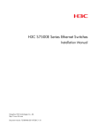
Figure 1 Airflow through the 7506-V chassis
4
4
4
3
3
2
1
1
(1) Inlet air vents for the power supplies
(2) Outlet air vents for the power supplies
(3) Inlet air vents for the chassis
(4) Outlet air vents for the chassis
5
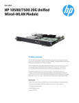
Figure 2 Airflow through other 7500 switch chassis
(1) Inlet air vents for the power supplies
(2) Outlet air vents for the power supplies
(3) Inlet air vents for the chassis
(4) Outlet air vents for the chassis
Space
For easy maintenance, follow these guidelines:
•
Reserve at least 1 m (3.28 ft) of clearance between the rack and walls or other devices.
•
The equipment room is at least 3 m (9.84 ft) high.
Installation tools
Table 6 lists the tools and equipment that you might need during installation. All of them are user
supplied.
Table 6 Installation tools and equipment
Category
Tool
Measuring and
marking tools
Long tape, ruler (of 1 meter), gradienter, marker, chalk line, and pencil
Drills
Percussion drill, electric drill, and several auxiliary drill bits
Flat-blade screwdriver P4-75 mm
Fastening tools
Phillips screwdriver P1-100 mm, P2-150 mm, and P3-250 mm
Socket wrench M5
Socket wrench M6
Small tools
Needle-nose pliers, diagonal pliers, combination pliers, wire-stripping pliers, crimping
pliers, RJ-45 crimping pliers, file, and handsaw
Auxiliary tools
ESD wrist strap, hair brush, tweezers, paper knife, hand bellows, electric iron, solder
wire, ladder, cable stripper, vacuum cleaner, crowbar, and rubber hammer
6
Category
Tool
Tools for fiber-optic
cleaning
Lint-free paper and optical fiber microscope
Equipment
Multimeter, 500 V Megohmmeter for measuring the insulation resistance, error
detector, optical power meter, and earth resistance tester
7
Installing the switch
IMPORTANT:
Keep the packages of the switch and the components for future use.
Figure 3 Hardware installation flow
Confirming installation preparations
Before you install the 7500 switch, verify that:
•
You have read the chapter "Preparing for installation" carefully and the installation site meets all the
requirements.
•
A 19-inch rack is ready for use. For how to install a rack, see the rack installation guide.
•
The rack is sturdy and securely grounded.
•
No debris exists inside or around the rack.
•
Choose a correct rack mounting position for the switch. Make sure the heaviest device is placed at
the bottom of the rack.
•
The switch is ready for installation and has been carried to a place near the rack.
8
Attaching slide rails and cage nuts to the rack
Installing slide rails
If the rack has slide rails, skip this section.
Before you attach slide rails to the rack, confirm the following items:
•
The slide rails can support the weight of the switch. For the weights of the 7500 switches, see
"Appendix A Chassis views and technical specifications."
HP recommends that you order the HP X421 A-Series Chassis Universal 4-Post Rack Mounting Kit
(JC665A). For more information about the kit, see "Appendix B FRUs and compatibility matrixes."
•
Identify the rack position for the switch. For the height and other specifications of the 7500 Switch
Series, see "Appendix A Chassis views and technical specifications."
Slide rail installation varies by rack type. The following installation procedure is for your reference only.
To install a slide rail:
1.
Read the signs on the slide rail (see Table 7) to avoid making a mistake.
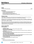
Figure 4 Right slide rail
(1) Sign
(2) Guide rail
(3)Installation hole
Table 7 Description of signs on the slide rails
Sign
Meaning
Remarks
F/L
Front end of the left slide rail
Mount this end to the front left rack post.
F/R
Front end of the right slide rail
Mount this end to the front right rack post.
9
2.
Mark the position on the rack for installing the slide rail.
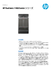
a. Make sure the bottom edge of the slide rail aligns with the middle of the narrower metal area
between holes, as shown in Figure 5.
b. Each rack post requires six screws to fix the slide rail. You only need to mark the uppermost
square hole and lowermost square hole for installation.
c. Mark the square holes at the same height on the other three rack posts.
One rack unit has three holes, the middle of which is an auxiliary installation hole, and the
other two are standard installation holes. You can distinguish them by the space between each
two holes. The space between a standard installation hole and an auxiliary installation hole is
larger than that between two adjacent standard installation holes.
Figure 5 Locating the rack position for installing slide rails
(1) Middle of the narrower metal area between holes
3.
Install six cage nuts on the square holes in each rack post, as shown in Figure 6.
Figure 6 Installing a cage nut
4.
Align the installation holes on the front end of the slide rail with the cage nuts on the front rack post,
and attach them with screws, as shown in Figure 7.
10
Figure 7 Attaching the slide rail to the cage nuts with screws
5.
Keep the slide rail horizontally and adjust its length until the installation holes in the rear end of the
slide rail touch the cage nuts on the rear rack post. Then screw in screws and fasten.
Insert a screw in each mounting hole of the slide rail to ensure its weight bearing capacity.
6.
Repeat steps 4 and 5 to install the other slide rail. Make sure the two slide rails are at the same
height so that the device can be placed on them horizontally.
11
Figure 8 Installed slide rails
Installing cage nuts
Before mounting the chassis to the rack, install cage nuts to the front square-holed brackets of the rack.
1.
As shown in Figure 9, determine the positions of the cage nuts according to the holes on the
mounting brackets and positions of the slide rails.
2.
Install cage nuts on the square holes on each rack post, as shown in Figure 6
12
Figure 9 Installing cage nuts (7503 as an example)
(1) Cage nut
Installing mounting brackets and cable management brackets
Before installing the switch to the rack, install the mounting brackets and cable management brackets
shipped with the switch. Cable management brackets (signal cable and power cable management
brackets) are used for cabling the switch, and mounting brackets are used for attaching the chassis to the
rack.
•
7506-V—Install the mounting brackets and cable management brackets separately to the chassis.
For more information, see "Installing the cable management brackets on the 7506-V" and
"Installing mounting brackets."
•
Other models—Install the cable management brackets to the mounting brackets, and then install
the mounting brackets to the chassis. For more information, see "Attaching the cable management
brackets on other models" and "Installing mounting brackets."
Installing the cable management brackets on the 7506-V
The 7506-V has two cable management brackets—the one with a tray is installed at the lower part of the
switch, and the one without a tray is installed at the upper part of the switch. They are installed in the
same way.
13
To install a cable management bracket:
1.
Unpack the cable management brackets.
2.
Attach the cable management bracket to the chassis, and align the screws with the screw holes in
the chassis, as shown in Figure 10.
3.
Fasten the screws.
Figure 10 Attaching cable management brackets on an HP 7506-V
2
4
3
5
3
1
2
1
(1) Attach the cable management bracket to the chassis
(2) Screw holes for installing the cable management bracket
(3) Screws for fixing the cable management bracket to the chassis
(4) Cable management bracket without a tray (installed at the upper part of the chassis)
(5) Cable management bracket with a tray (installed at the lower part of the chassis)
Attaching the cable management brackets on other models
For the models except the 7506-V, install the cable management bracket on the left mounting bracket, as
shown in Figure 11. The switch is supplied with two mounting brackets, and the one with the cable
management bracket screw holes is the left mounting bracket.
14
Figure 11 Attaching the cable management bracket to the left mounting bracket
(1) Left mounting bracket
(2) Cable management bracket
(3) Screw hole for installing the cable management bracket
(4) Screw for fixing the cable management bracket to the left mounting bracket
Installing mounting brackets
Before installing the switch to the rack, install the mounting brackets to the chassis, as shown in Figure 12.
•
7506-V—Facing the front of the switch, mount the left and right mounting bracket to the two sides
of the switch.
•
Other models—Facing the front of the switch, mount the mounting bracket with a cable
management bracket to the left of the switch, and mount the mounting bracket without a cable
management bracket to the right of the switch (where the fan assembly is located).
Figure 12 Installing the mounting brackets (7503)
3
2
1
1
(1) Screws for fixing the mounting brackets to the chassis
(3) Right mounting bracket
15
(2) Left mounting bracket
Mounting the switch to the rack
CAUTION:
• Do not hold the handle of the fan assembly, power supply, or the back cover of the chassis, or the air
vents of chassis. Any attempt to carry the switch with these parts might cause equipment damage or
even bodily injury.
• After placing the switch on the slide rails, do not leave go of your hands immediately because this might
tip the switch, damaging the switch or even causing bodily injury.
To mount the switch in the rack:
1.
Move the chassis to face the rear of the chassis towards the front of the rack.
2.
Use at least two persons to lift the switch until the bottom of the switch is a little higher than the slide
rails on the rack.
HP recommends using a mechanical lift for moving your switch.
3.
Place the switch on the slide rails and slide the switch along the slide rails until the mounting
brackets on the switch touch the front rack posts, as shown in callout 1 on Figure 13.
4.
Attach the chassis to the rack with mounting screws.
Figure 13 Installing the chassis to the rack (7503)
(1) Slide the chassis into the rack
(2) Left mounting bracket
(3) Right mounting bracket
(4) Screws for fixing the mounting brackets to the rack
If the screw holes in the mounting brackets cannot align with the cage nuts on the rack, verify that the
bottom edge of the slide rail aligns with the middle of the narrowest metal area between holes and that
the cage nuts are installed in the correct holes.
16
Grounding the switch
CAUTION:
Before you use the switch, connect the grounding cable correctly to guarantee lightning protection and
anti-interference of the switch.
Grounding the switch with a grounding strip
CAUTION:
• Use the supplied grounding cable (yellow-green grounding cable).
• Connect the grounding cable to the earthing system in the equipment room. Do not connect it to a fire
main or lightning rod.
If a grounding strip is available at the installation site, connect the grounding cable through the
grounding strip.
To connect the grounding cable:
1.
Unpack the grounding cable.
The grounding cable provided with the switch series is compliant with the NEBS standards.
2.
Remove the grounding screws from the rear panel of the switch chassis, as shown in callout 2
on Figure 14.
3.
Attach the grounding screw to the dual-hole terminal of the grounding cable.
4.
Use a screwdriver to fasten the grounding screw into the grounding screw hole.
5.
Connect the ring terminal of the grounding cable to the grounding post of the grounding strip, and
fasten the grounding cable to the grounding strip with the hex nut.
Figure 14 Connecting the grounding cable to a grounding strip
(1) Attach the grounding screws with dual-hole terminals to the grounding holes
(2) Grounding holes
(3) Grounding strip
(5) Ring terminal
(6) Hex nut
17
(4) Grounding post
Grounding the switch through the PE wire of an AC power
supply
If the installation site has no available grounding strips, you ground an AC-powered switch through the
PE wire of the AC power supply.
CAUTION:
Make sure the AC power supply uses a three-wire cable with a protection wire, and the PE wire of the AC
power supply is well grounded at the power distribution room or AC power supply transformer side. In
addition, make sure the PE connector on the switch is well connected to the PE wire of the AC power
supply.
Figure 15 Grounding through an AC power PE wire
Grounding the switch through the RTN wire of a DC power
supply
If the switch is powered by a –48 VDC power supply and no grounding strip is available at the
installation site, you can ground the switch through the return (RTN) wire of the DC power supply, as
shown in Figure 16.
CAUTION:
Make sure the RTN wire is well grounded from the DC egress of the DC power cabinet.
18
Figure 16 Grounding through the PGND of a power cabinet
19
Installing FRUs
There is no required order for installing FRUs. HP recommends that you connect power cords after
completing installing all required FRUs.
TIP:
Keep the chassis and the component packages for future use.
Attaching an ESD wrist strap
Every 7500 switch provides an ESD wrist strap. To minimize ESD damage to electronic components,
wear an ESD wrist strap and ensure it is well grounded when installing modules.
To attach an ESD wrist strap:
1.
Make sure the switch is well grounded. For how to ground your switch, see "Installing the switch."
2.
Wear the wrist strap.
3.
Tighten the wrist strap to keep good skin contact. Make sure the resistance reading between your
body and the ground is between 1 and 10 megohms.
4.
As shown in Figure 17, insert the ESD wrist strap into the ESD port on the switch chassis, or attach
it to the grounding screw of the chassis with an alligator clip.
Figure 17 Attaching an ESD-prevent wrist strap (7503 as an illustration)
1
(1) ESD wrist strap port (having an ESD sign)
20
Installing a card
All the MPUs and LPUs for the switch series are hot swappable. The installation procedures for MPUs and
LPUs are the same. Unless otherwise stated, MPUs and LPUs are collectively referred to as "cards" in this
document.
To install a card:
1.
Wear an ESD wrist strap, and make sure it makes good skin contact and is well grounded. For
more information, see "Attaching an ESD wrist strap."
2.
As shown in callout 1 on Figure 18, remove the blank filler (if any) from the slot to be used. Keep
the blank filler correctly for future use.
3.
As shown in callout 2 on Figure 18, hold the card by the front panel with one hand and support
the card bottom with the other (do not touch its circuit). Slide the card steadily into the slot along
the guide rails.
4.
As shown in callout 3 on Figure 18, when most part of the card is inserted in the slot, press the
ejector levers on the card outward.
5.
Push the card until the positioning pin on card touches the hole on the chassis.
6.
As shown in callout 4 on Figure 18, press the ejector levers inward until the ejector levers touch the
panel tightly and the card seats into the backplane.
7.
As shown in callout 5 on Figure 18, fasten the captive screws on the card.
8.
When the switch is powered on, examine the running status of the card.
You can examine the running status of a card by referring to the card status LED (SLOT) on the MPU
of the switch. If the RUN LED flashes, the card in the slot operates correctly. For more information
about card status LED (SLOT), see "Appendix C LEDs."
After the switch is powered on, you can examine the card running status at the command line
interface (CLI). For more information, see "Hardware management and maintenance."
Figure 18 Installing a card
(1) Remove the blank filler
(2) Slide the card into the slot along the guide rails
(3) Press the ejector levers on the card outward
(4) Press the ejector levers on the card inward
(5) Fasten the captive screws
21
Installing a power supply
CAUTION:
• For dual-grid input, the input voltage and frequency for the two grids must be the same.
• Provide a circuit breaker for each power supply and make sure the circuit breaker is off before
installation.
• Do not install power supplies of different models on the same switch.
• To avoid power supply damage or bodily injury, support the bottom of a power supply instead of
holding its handle for power supply movement.
• Before installing a power supply, make sure the power supply is switched off.
• Make sure the power of the power supply can satisfy the requirements of the switch.
The switch uses 1 + 1 power redundancy and supports AC and DC power input. You can select AC or
DC power supply as needed. For more information about optional power supplies, see "Appendix B
FRUs and compatibility matrixes."
Installing a power supply
CAUTION:
If the captive screws cannot be fastened, verify that the power supply is correctly installed.
To install the power supply:
1.
Wear an ESD wrist strap and make sure it makes good skin contact and is well grounded. For
more information, see "Attaching an ESD wrist strap."
2.
As shown in callout 1 on Figure 19, remove the blank filler (if any) from the slot to be used. Keep
the blank filler correctly for future use.
3.
Unpack the power supply, and verify that the power supply model is correct.
4.
Be sure to insert the power supply with its upside up. Grasp the handle of the module with one
hand and support the module bottom with the other.
5.
As shown in callout 2 on Figure 19, gently push the power supply along the guide rails into the slot
until it has firm contact with the slot.
6.
As shown in callout 3 on Figure 19, use a Phillips screwdriver to fasten the captive screws on the
power supply to secure the power supply into the chassis.
22
Figure 19 Installing a power supply
2
3
1
(1) Remove the blank filler
3
(2) Push the power supply along the guide rails into the slot
(3) Fasten the captive screws
Follow the forward inertia of the power supply when inserting it into the chassis to ensure that the power
supply has firm contact with the connector on the backplane.
To prevent damage to the power supply and the connection terminals on the backplane, be sure to pull
out the power supply first in case of any misalignment, and then push it in again.
Connecting the power cord
WARNING!
Before connecting the power cord, make sure the power supply that connects to the power cord is switched
off.
Table 8 Power cord connection for the 7500 Switch Series
Model
Power input
(AC/DC)
PoE support
Power cord connection procedure
300W AC
AC
No
Connecting the 300W AC/650W AC power cord
650W AC
AC
No
Connecting the 300W AC/650W AC power cord
1400W AC
AC
No
Connecting a 1400W AC power cord
2800W AC
AC
Yes
Connecting a 2800W AC power cord
6000W AC
AC
Yes
Connecting a 6000W AC power cord
300W DC
DC
No
Connecting the 300W DC/650W DC power cord
650W DC
DC
No
Connecting the 300W DC/650W DC power cord
1400W DC
DC
Yes
Connecting the 1400W DC power cord
Typically 10 A busbars are available in the equipment room but the 1400W AC, 2800W AC, and
6000W AC power supplies require a 16 A power cord (AC), so you need to use a 16 A busbar, and
23
ensure that the AC power supply system can provide enough power. For the power cords used in different
countries or regions, see "Appendix B FRUs and compatibility matrixes."
Connecting the 300W AC/650W AC power cord
The 300W AC and 650W AC are built-in power supplies with AC input and DC output to supply power
to the switch. Before connecting power cord, make sure the power switch is in the off position.
To connect the AC power cord:
1.
Make sure of the power cord model (the 300W AC and 650W AC use a 10 A AC power cord).
2.
Plug the power cord to the power receptacle on the power supply, and ensure a good contact.
3.
Plug the other end of the power cord to the AC power strip of the AC power source.
4.
Turn on the power switch.
5.
Examine the power supply input status LED.
If the LED is green, the power cord is correctly connected. If the LED is off or red, examine the
installation, and solve the problem. Then switch on the power supply to verify that the LED is green.
For description of 300W AC and 650W AC status LEDs, see "Appendix C LEDs."
Figure 20 Connecting an AC power cord
3
2
1
(1) AC power cord
(2) Power switch (O for off, and | for on)
(3) Power supply status LED
Connecting a 1400W AC power cord
The 1400W AC is a built-in power supply with AC input and DC output to supply power to the switch.
Before connecting power cord, make sure the power switch is in the off position.
24
Figure 21 Panel view of the 1400W AC
(1) Captive screws
(2) Power switch (O for off, and | for on)
(3) Status LEDs
(4) AC receptacle
(5) Hole for fixing a cable tie
(6) Power supply handle
To connect the AC power cord:
1.
Make sure of the power cord model (the 1400W AC uses a 16 A AC power cord).
2.
Plug the power cord to the power receptacle on the power supply, and ensure a good contact.
3.
Secure the power cord to the power supply handle by using a cable tie, as shown in Figure 22.
4.
Plug the other end of the power cord to the AC power receptacle of the power source.
5.
Turn on the power switch.
6.
Examine the power supply input status LED.
If the LED is green, the power cord is correctly connected. If the LED is off or red, examine the
installation, and solve the problem. Then switch on the power supply to verify that the LED is green.
For description of 1400W AC status LEDs, see "Appendix C LEDs."
25
Figure 22 Connecting an AC power cord
Connecting a 2800W AC power cord
The 2800W A is a built-in power supply with AC input and DC output. The 2800W AC power supply
can provide the switch with both system power and PoE power, which can be controlled through separate
switches. Before connecting power cord, make sure the system power switch PoE power switch both are
in the off position.
The 2800W AC provides the system power receptacle (callout 2) and the PoE power receptacle (callout
5).
26
Figure 23 Panel view of the 2800W AC
(1) Captive screws
(2) System power receptacle
(3) Power switch (O for off, and — for on)
(4) Status LEDs
(5) PoE power receptacle
(6) PoE power switch (O for off, and — for on)
(7) Hole for fixing a cable tie
(8) Power supply handle
The power cord connection procedures are the same for the system power receptacle and PoE power
receptacle of the 2800W AC power supply. This section takes the system power receptacle for example.
To connect the AC power cord to the system power receptacle of the power supply:
1.
Make sure of the power cord model (the 2800W AC uses a 16 A AC power cord).
2.
Plug the power cord to the system power receptacle on the power supply, and ensure a good
contact.
3.
Secure the power cord to the power supply handle by using a cable tie, as shown in Figure 24.
4.
Plug the other end of the power cord to the AC power receptacle of the power source.
5.
Turn on the power switch.
6.
Examine the power supply input status LED.
If the LED is green, the power cord is correctly connected. If the LED is off or red, examine the
installation, and solve the problem. Then switch on the power supply to verify that the LED is green.
For description of 2800W AC status LEDs, see "Appendix C LEDs."
27
Figure 24 Connecting an AC power cord
Connecting a 6000W AC power cord
The 6000W AC power supply is a built-in power supply with AC input and DC output. It provides the
device with both system power and PoE power, which can be controlled through separate switches.
Before connecting power cord, make sure the system power switch PoE power switch both are in the off
position.
Each 6000W AC power supply has four independent AC receptacles, where, callout 4 shows the system
power receptacle and callout 8 shows the PoE power receptacles (PoE1, PoE2, and PoE3).
28
Figure 25 Panel view of the 6000W AC
1
2
8
3
4
3
7
6
5
(1) Captive screws
(2) PoE power switch (O for off, and | for on)
(3) Status LEDs
(4) System power receptacle
(5) System power switch (O for off, and | for on)
(6) Holes for fixing cable ties
(7) Power supply handle
(8) PoE power receptacles
The power cord connection procedures are the same for the system power receptacle and PoE power
receptacle of the 6000W AC power supply. This section takes the system power receptacle for example.
To connect an AC power cord to the system power receptacle of the power supply:
1.
Make sure of the power cord model (the 6000W AC power supply uses a 16A AC power cord).
2.
Plug the power cord into the system power receptacle on the power supply, and ensure a good
contact.
3.
As shown in Figure 26, secure the power cord to the power supply handle by using a cable tie.
4.
Plug the other end of the power cord to the AC power receptacle of the power source.
5.
Turn on the power switch.
6.
Examine the power supply input status LED.
If the LED is green, the power cord is correctly connected. If the LED is off or red, examine the
installation, and solve the problem. Then switch on the power supply to verify that the LED is green.
For description of 6000W AC status LEDs, see "Appendix C LEDs."
29
Figure 26 Connecting an AC power cord
Connecting the 300W DC/650W DC power cord
CAUTION:
When connecting the power cord, make sure the circuit breaker is completely turned off for both the
positive and negative lines.
To connect the DC power cord:
1.
Take off the protection cover.
2.
Use a No. 2 Phillips screwdriver to loosen the screws on the wiring terminals.
3.
Connect the end of the blue DC power cord marked with – to the negative terminal (–) on the
power supply, and fasten the screw.
4.
Connect the end of the black DC power cord marked with + to the positive terminal (+) on the
power supply, and fasten the screw.
5.
Put the protection cover on the wiring terminals.
6.
Connect the other ends of the DC power cords to the wiring terminals that provide a power supply
to the switch.
Figure 27 Connecting a DC power cord
(1) Protection cover
(2) Screws
(3) Wiring terminal
(4) Grounding point
30
Connecting the 1400W DC power cord
CAUTION:
When connecting the power cord, make sure the circuit breaker is completely turned off for both the
positive and negative lines.
To connect the DC power cord:
1.
Loosen the captive screws on the protection cover with a Phillips screwdriver and remove the
protection cover. There are two flat washers, one spring washer, and one M6 fastening nut from
inside to outside on each wiring terminal.
2.
Loosen the captive nuts on four wiring terminals with a M6 socket wrench, and remove the captive
nut, spring washer, and one flat washer in turn from each wiring terminal.
3.
Connect the end of the blue DC power cord marked with – to the negative terminal (–) on the
power supply.
4.
Connect the end of the black DC power cord marked with + to the positive terminal (+) on the
power supply.
5.
Put the flat washer and spring washer on the wiring terminal in turn and screw up the captive nut
with the M6 socket wrench. Repeat this step for the other three terminals.
6.
Put the protection cover on the wiring terminals and faster the captive screws.
7.
Connect the other ends of the DC power cords to the wiring terminals that provide a power supply
to the switch.
Figure 28 Connecting a DC power cord
(1) M6 screw
(2) Spring washer
(3) Flat washer
(4) Wiring terminal
31
Setting up a PoE system (optional)
CAUTION:
• If you do not use the PoE function, verify that the PoE power switch on the power supply is off.
• To ensure steady operation of the switch when the switch uses a 1400W DC to supply PoE power, if the
total power consumption of the switch (the system power consumption plus the PoE power consumption)
is greater than 3300W, use the 1/0 AWG cable (with 53 mm2 or 0.08 in2 cross section). HP
recommends that you order the HP X210 JG2 to T50 3m DC (2) Power Cables (JG333A). For more
information about the cables, see "Appendix B FRUs and compatibility matrixes."
• When the switch uses a 1400W DC to supply PoE power, you can monitor the working status of the
external power supply through the PoE power monitoring port. The PoE power monitoring port is an
RS-485 compliant port. You can select an RS-485 compliant connection method according to the
monitoring port type. When you use a –48 V DC power supply, you do not need to monitor the working
status of the external power supply.
• When the switch uses a 6000W AC to supply PoE power, make sure the input voltage for the system
power input, PoE 1, PoE 2, and PoE 3 are the same. It can be either 110 VAC or 220 VAC for power
supplies of the power supply.
Requirements
Power over Ethernet (PoE) enables a power sourcing equipment (PSE) to supply power to powered
devices (PDs) from Ethernet interfaces through twisted pair cables. Commonly used PDs include: IP
telephones, wireless LAN access points (APs), and web cameras.
The following PoE types are available:
•
Type 1—Power delivered by a single port: 0 to 15.4 W; voltage range: 44 V to 57 V; maximum
current: 350 mA. This PoE type provides power to classes 0 to 3 PDs.
•
Type 2—Power delivered by a single port: 0 to 30 W, voltage range: 50 V to 57 V, maximum
current: 600 mA. This PoE type provides power to classes 0 to 4 PDs.
To set up a PoE system for the 7500 Switch Series, the following requirements should be met:
Cards supporting PoE
•
The 7500 Switch Series can implement the PoE function through the cards listed in Table 9.
•
Except the LSQ3GV48SC0 and LSQ1GV48SD0, all the other cards require a PoE dual in-line
memory module (DIMM) to implement the PoE function. PoE DIMMs fall into the following types: HP
7500 24-port PoE DIMM(JC671A) and HP 7500 48-port PoE DIMM(JD192B). For the compatibility
between the two types of modules and cards, see Table 9. For the installation of a PoE DIMM, see
"Installing a PoE DIMM."
•
The LSQ1GV48SD0 and LSQ3GV48SC0 each can provide a maximum of 806 W power through
PoE. When you use the cards to power devices through PoE, make sure the total power of PDs does
not exceed 806 W.
32
Table 9 Cards supporting PoE
Card model
Number of
POE-capable ports
LSQ1GV48SD0
48
LSQ3GV48SC0
48
LSQ1CGV24PSC0
24
LSQ1GV24PSC0
24
LSQ1GV24PSA0
24
LSQ1FV48SA0
48
LSQ1GV48SA0
48
LSQ1GV48SC0
48
LSQ1GV40PSC0
40
PoE DIMM
PoE type
No PoE DIMM needed
Type1, Type2
HP 7500 24-port PoE DIMM(JC671A)
Type 1
HP 7500 48-port PoE DIMM(JD192B)
Power supplies supporting PoE
•
The power supplies 650W AC, 650W DC, 300W AC, and 300W DC for the 7502 and 7503-S
do not support PoE. To enable PoE on these switches, use an external PoE power supply (for example,
A-RPS800). For how to connect an external PoE power supply, see "Connecting an external PoE
power supply."
•
To implement PoE on the 7503, 7506, 7506-V, or 7510, you can select power supplies supporting
PoE. For description of the power supplies supporting PoE, see Table 10.
Table 10 Power supplies supporting PoE
Power supply
model
PoE maximum power output
Separate PoE power
cord
Power cord connection
procedure
1400W DC
6720 W
No
Connecting the 1400W DC
power cord
Yes
Connecting a 2800W AC
power cord
Yes
Connecting a 6000W AC
power cord
2800W AC
1150 W (110 V)
1400 W (220 V)
One-line input
6000W AC
Two-line input
Three-line
input
1200 W (110 V)
1800 W (220 V)
2400 W (110 V)
3600 W (220 V)
3600 W (110 V)
5300 W (220 V)
Installing a PoE DIMM
The PoE DIMM installed on a card can implement the PoE function. It falls into HP 7500 24-port PoE
DIMM(JC671A) and HP 7500 48-port PoE DIMM(JD192B).
33
Installing an HP 7500 24-port PoE DIMM (JC671A)
CAUTION:
• Avoid touching the components on the PoE DIMM and PCB during installation and removal of a PoE
DIMM.
• If no PoE DIMM is in place or the module is not fully seated, the interface card cannot supply power,
though other functions work well.
HP 7500 24-port PoE DIMM(JC671A) is applicable to LSQ1CGV24PSC0, LSQ1GV24PSC0, and
LSQ1GV24PSA0.
The PoE DIMM slot is a reverse insertion prevention slot to help you identify the direction for installing a
PoE DIMM.
To install an HP 7500 24-port PoE DIMM(JC671A):
1.
Wear an ESD wrist strap and make sure it makes good skin contact and is well grounded. For
more information, see "Attaching an ESD wrist strap."
2.
Place the card steadily. Then find the PoE DIMM slot (there is a master mark on the PCB under the
slot) on the PCB.
3.
Pull the white clips on the two sides of the PoE DIMM slot outward, as shown in callout 1 on Figure
29.
4.
Unpack the PoE DIMM, and align the golden finger of the PoE DIMM with the groove on the slot.
5.
As shown in Figure 29, use your thumbs to press the edges of the PoE DIMM and push it along the
guide rail into the slot until the white clips click into the grooves on the two sides of the PoE DIMM.
6.
Verify that the clips lock the PoE DIMM.
Figure 29 Installing a PoE DIMM
(1) Pull the white clips on the two sides of the DIMM outward
(2) Press the edges of the PoE DIMM and push it into the slot along the guide rail
(3) The white clips automatically click into the grooves on the two sides of the DIMM
34
Installing a master/slave DIMM
CAUTION:
• Determine the master or slave HP 7500 48-port PoE DIMM (JD192B) before installation. For how to
distinguish them, see Figure 30.
• Plug the master DIMM into the master DIMM slot (there is a "Master" mark on the PCB under the slot),
and the slave DIMM into the slave DIMM slot (there is a "Slave" mark on the PCB under the slot).
• The master and slave DIMMs must be used simultaneously. The PoE system operates correctly only when
both of them are inserted in the correct slots.
• Avoid touching the components on the PoE DIMM and PCB during installation and removal of a PoE
DIMM.
HP 7500 48-port PoE DIMM(JD192B) is applicable to LSQ1FV48SA0, LSQ1GV48SA0, LSQ1GV48SC0,
and LSQ1GV40PSC0.
Figure 30 PoE master/slave DIMM
(1) There is a chip on the master DIMM, but not on the slave DIMM.
To install a PoE DIMM:
1.
Wear an ESD wrist strap and make sure it makes good skin contact and is well grounded. For
more information, see "Attaching an ESD wrist strap."
2.
Place the card steadily. Then find the master PoE DIMM slot (there is a Master mark on the PCB
under the slot) on the PCB.
3.
Pull the white clips on the two sides of the PoE DIMM slot outward, as shown in callout 1 on Figure
29.
4.
Unpack the master PoE DIMM, and align the golden finger of the PoE DIMM with the groove on the
slot.
5.
As shown in Figure 29, use your thumbs to press the edges of the master PoE DIMM and push it
along the guide rail into the slot until the white clips click into the grooves on the two sides of the
PoE DIMM.
6.
Verify that the clips lock the master PoE DIMM.
7.
Repeat steps 3 through 6 to install the slave DIMM to the slave DIMM slot (there is a Slave mark on
the PCB under the slot).
35
Connecting an external PoE power supply
CAUTION:
To ensure steady operation of the switch, when you use your own PoE power cord, make sure the cross
section of the cable is no less than 8.4 mm2 (0.01 in2) and the power cord can carry 50 A current.
To supply PoE power to 7502 or 7503-S, a PoE power cord is required to connect the external PoE power
supply to the PoE input on the chassis rear panel. You can use an A-RPS800 or other DC power supplies
that can satisfy PoE input requirements: voltage range –46 V to –57 V (–52 V to –57 V for type 2) and
maximum current 40 A, as the external PoE power supply.
If you use an A-RPS800 as the external PoE power supply, HP recommends that you order the HP X290
14-pin Mini-Fit to 2 x OT Copper Lug 1m RPS Power Cable (JG332A). For more information about the
cable, see "Appendix B FRUs and compatibility matrixes."
Connecting the A-RPS 800 to the switch
1.
Remove the blank panel covering the PoE port of the switch.
2.
Connect the OT terminal (with a – sign) on the blue wire to the NEG(–) terminal on the PoE power
supply socket, and fasten the captive screw. Connect the OT terminal (with a + sign) on the black
wire to the RTN(+) terminal on the PoE power supply socket, and fasten the captive screw.
3.
Install the blank panel to the PoE port.
4.
Connect the PoE power cord to the A-RPS 800: Plug the H2*7 of the PoE power cord into the DC
output of the A-RPS 800, and then fasten the screw, as shown in callout 5 on Figure 31.
5.
Supply power to the A-RPS 800: Plug the female end of the AC power cord into the AC input on
the A-RPS 800 and ensure a good contact, and plug the male end of the AC power cord into the
external power supply socket.
Figure 31 Connecting the A-RPS 800
1
2
7
4
3
6
5
(1) NEG(–) terminal
(2) RTN(+) terminal
(3) Grounding point
(4) DC output
(5) Insert the H2*7 plug of the PoE power cord into the DC output
(6) AC input
(7) A-RPS 800
36
For more information about the A-RPS 800, see HP A-RPS 800 Redundant Power System User Guide.
Connecting a user-supplied power cord to the PoE input on the chassis rear panel
CAUTION:
To avoid damage to the switch, be sure to connect the negative terminals to negative terminals and
positive terminals to positive terminals.
To connect a user-supplied power cord to the PoE input on the chassis rear panel:
1.
Remove the blank panel covering the PoE port of the switch.
2.
Connect the negative OT terminal on the PoE power cord to the NEG(–) terminal on the PoE power
supply socket, and fasten the captive screw. Connect the positive OT terminal on the PoE power
cord to the RTN(+) terminal on the PoE power supply socket, and fasten the captive screw.
3.
Install the blank panel to the PoE port.
4.
Connect the PoE power cord to the external PoE power supply.
Figure 32 Connecting a user-supplied power cord
(1) NEG(-) terminal
(2) RTN(+) terminal
(3) Grounding point
Installing a CF card to an MPU (optional)
If you select an MPU supporting CF card, you can install a CF card as needed.
To install a CF card:
1.
Push the CF card eject button all the way into the slot, and make sure the button does not project
from the panel.
2.
Push the CF card all the way into the CF card slot, so that it does not automatically project, as
shown in callout 4 of Figure 33. At the same time, the eject button projects.
3.
When the switch is powered on, examine the running status of the CF card.
37
To examine the CF card status, examine the CFS LED on the MPU of the switch. If the LED is on, the
CF card is correctly installed. For more information about CFS LED description, see "Appendix C
LEDs."
After the switch is powered on, you can examine the CF card running status at the CLI. For more
information, see "Hardware management and maintenance."
Figure 33 Installing a CF card
(1) CF card eject button
(2) CF card
(3) CF card status LED
(4) Insert the CF card into the slot
Installing a transceiver module (optional)
CAUTION:
• To avoid component damage, read this section carefully before installing a transceiver module.
• Do not remove the protection cover from a transceiver module before connecting an optical fiber.
• Remove the optical fiber, if any, from a transceiver module before installing it.
The transceiver modules available for the switch include SFP, SFP+, XFP, QSFP+, and CFP.
Installing an XFP/SFP+/SFP/QSFP+ transceiver module
1.
Wear an ESD wrist strap and make sure it makes good skin contact and is well grounded. For
more information, see "Attaching an ESD wrist strap."
2.
Unpack the module. Do not touch the golden finger of the module.
3.
Pivot the clasp of the module up. Holding the module, gently push the module into the slot until it
has firm contact with the slot (when the top and bottom spring tabs catch in the slot), as shown
in Figure 34.
{
For a QSFP+ module that uses a plastic pull latch, skip this step. QSFP+ modules use either a
metal or plastic pull latch. They are installed in the same way except that you must pivot the
clasp up for the module that uses a metal pull latch.
38
{
{
4.
For an SFP+ module, press the module down against the upward force of the bottom spring tab
so you can push the module straight into the port.
If you cannot hold the module by its two sides because of high module density, press the module
on its head end to push it in.
Connect the fiber to the module. For the installation procedure, see "Connecting your switch to the
network."
Figure 34 Installing an XFP/SFP+/SFP/QSFP+ module
Installing a CFP module
1.
Wear an ESD wrist strap and make sure it makes good skin contact and is well grounded. For
more information, see "Attaching an ESD wrist strap."
2.
Unpack the CFP module. Do not touch the golden finger of the module.
3.
Holding both sides of the module, gently push the module into the slot until it has firm contact with
the slot. See Figure 35.
4.
Fasten the captive screws.
5.
Connect the fiber to the module. For the installation procedure, see "Connecting your switch to the
network."
Figure 35 Installing a CFP module
2
2
1
(1) Gently push the module into the slot
(2) Fasten the captive screws
39
Connecting an SFP+/QSFP+/QSFP+ to SFP+ cable
Use SFP+ cables to connect SFP+ ports, QSFP+ cables to connect QSFP+ ports, and QSFP+ to SFP+
cables to connect QSFP+ and SFP+ ports. All these cables are hot swappable.
To connect an SFP+, QSFP+, or QSFP+ to SFP+ cable:
1.
Wear an ESD wrist strap and make sure it makes good skin contact and is well grounded. For
more information, see "Attaching an ESD wrist strap."
2.
Unpack the cable.
3.
Plug the cable connector into the port. Make sure the cable connector is the right side up.
The bend radius of the cable must be at least eight times the cable diameter.
40
Setting up an IRF fabric
You can use HP IRF technology to connect and virtualize 7500 switches into a large virtual switch called
an "IRF fabric" for flattened network topology, high availability, scalability, and manageability. For more
information about IRF, see HP 7500 Switch Series IRF Configuration Guide.
IRF fabric setup flowchart
Figure 36 IRF fabric setup flowchart
NOTE:
For the actual procedure, see HP 7500 Switch Series IRF Configuration Guide for the software release you
are using.
Planning IRF fabric setup
This section describes issues that an IRF fabric setup plan must cover.
Planning IRF fabric size and the installation site
Plan IRF fabric size and the installation site, as follows:
1.
Use HP 7500 Switch Series IRF Configuration Guide as a reference to identify the number of
member switches that your system software version supports for a 7500 IRF fabric.
41
2.
Choose 7500 switch models for your network.
IRF-capable 7500 switches include the 7503, 7506, 7510, and 7506-V.
The member switches in a 7500 IRF fabric must be the same model.
3.
Select LPUs that can provide 10-GE/40-GE optical ports.
The 7500 switch series requires 10-GE/40-GE optical ports for IRF connection. Available cards
include the LSQ1SRP2XB (JD193B) MPU, and the SC–, SD–, and EB–type LPUs. For more
information about the LPUs, see "Appendix B FRUs and compatibility matrixes"
4.
Select XFP/SFP+/QSFP+/CFP transceiver modules and fibers for long-haul IRF connection. Select
SFP+/QSFP+/QSFP+ to SFP+ cables for short-haul IRF connection.
For more information about transceiver modules and cables, see "Appendix B FRUs and
compatibility matrixes."
5.
Plan the installation site.
Identifying the master switch and planning IRF member IDs
Determine which switch you want to use as the master for managing all member switches in the IRF
fabric.
An IRF fabric has only one master switch. You configure and manage all member switches in the IRF
fabric at the CLI of the master. IRF member switches will automatically elect a master. You can affect the
election result by assigning a high member priority to the intended master switch. For more information
about master election, see HP 7500 Switch Series IRF Configuration Guide.
Prepare an IRF member ID assignment scheme. An IRF fabric uses member IDs to uniquely identify and
manage its members, and you must assign each IRF member switch a unique member ID.
Planning IRF topology and connections
Connect the IRF member switches through IRF ports, the logical interfaces for the connections between
IRF member switches. Each IRF member switch has two IRF ports: IRF-port 1 and IRF-port 2. To use an IRF
port, you must bind at least one physical port to it.
When connecting two neighboring IRF member switches, you must connect the physical ports of IRF-port
1 on one switch to the physical ports of IRF-port 2 on the other switch.
A two-member IRF fabric must use the daisy chain topology.
If the system software version you are using supports more than two IRF members, you can create an IRF
fabric that comprises more than two members in daisy chain topology, or more reliably, ring topology.
In ring topology, the failure of one IRF link does not cause the IRF fabric to split as in daisy chain topology.
Rather, the IRF fabric changes to a daisy chain topology without interrupting network services.
Identifying physical IRF ports on the member switches
Identify the physical IRF ports on the member switches according to your topology and connection
scheme.
On 7500 switches, only 10-GE/40-GE ports can be used for IRF connection.
The 7500 switches support multi-card link aggregation for IRF ports. You can bind up to eight physical
ports to one IRF port.
42
Installing IRF member switches
Step
Reference
1.
Prepare the installation site
Preparing for installation
2.
Rack mount the IRF member switches to racks
Installing the switch
3.
Install modules on IRF member switches
Installing FRUs
Configuring basic IRF settings
CAUTION:
If one or two LSQ1SRP2XB MPUs are used, the switch automatically creates one virtual LPU slot for each
MPU slot, and the LPU slot numbers are higher than the largest physical LPU slot number. To bind the XFP
ports on one MPU to an IRF port, you must access the virtual LPU for the MPU. You can use the display
device command to display information about the virtual LPU slots.
After you install the IRF member switches, power on the switches, and log in to each IRF member switch
(see "Connecting your switch to the network") to configure their member IDs, member priorities, and IRF
port bindings.
Follow these guidelines when you configure the switches:
•
You must first configure the member IDs, member priorities, and IRF port bindings for the IRF
member switches, save the configuration, connect the member switches, and change the operating
mode of the switches to IRF mode.
•
Assign the master switch higher member priority than any other switch.
•
Bind physical ports to IRF port 1 on one switch and to IRF port 2 on the other switch.
•
Execute the display irf configuration command to verify the basic IRF settings.
For more information about configuring basic IRF settings, see HP 7500 Switch Series IRF Configuration
Guide.
Connecting the physical IRF ports
Connect the physical IRF ports of switches by following these guidelines.
•
Use XFP transceiver modules and fibers to connect 10-Gigabit XFP ports.
•
You can use SFP+ transceiver modules and fibers, or use SFP+ cables to connect SFP+ ports. SFP+
cables are used over a relatively short distance.
•
Use CFP transceiver modules and fibers to connect CFP ports.
•
When connecting XFP/SFP+/CFP ports, connect the transmit port of an XFP/SFP+/CFP transceiver
module at one end to the receive port of an XFP/SFP+/CFP transceiver module at the other end.
•
Use QSFP+ transceiver modules and fibers for long-haul connection, or use QSFP+ cables to
connect QSFP+ ports for short-haul connection.
•
The transceiver modules at the two ends of an IRF link must be the same type.
43
For more information about installing transceiver modules, see "Installing FRUs." For more information
about connecting fibers, see "Connecting your switch to the network."
Figure 37 Connecting two IRF member switches
Verifying the IRF fabric configuration
After you finish configuring basic IRF settings and connecting IRF ports, verify the basic functionality of
the IRF fabric, as follows:
1.
Log in to the IRF fabric through the console port of any member switch.
2.
Create a Layer 3 interface, assign it an IP address, and make sure the IRF fabric and the remote
network management station can reach each other.
3.
Use Telnet or SNMP to access the IRF fabric from the network management station. (See HP 7500
Switch Series Fundamentals Configuration Guide.)
4.
Verify that you can manage all member switches as if they were one node.
5.
Display the running status of the IRF fabric by using the commands in Table 11.
Table 11 Displaying and maintaining IRF configuration and running status
Task
Command
Display information about the IRF fabric
display irf
Display topology information about the IRF fabric
display irf topology
NOTE:
To avoid IP address collision and network problems, configure at least one MAD mechanism to detect the
presence of multiple identical IRF fabrics and handle collisions. For more information about MAD, see HP
7500 Switch Series IRF Configuration Guide.
44
Connecting your switch to the network
This chapter describes how to connect your switch to a network.
The first time you access a switch you must log in through the console port. On the switch, you can
configure Telnet or SSH for remote access through Ethernet ports. You manage console login users at
AUX user interfaces, and manage Telnet and SSH users at VTY user interfaces. For more information
about login methods and user interfaces, see HP 7500 Switch Series Fundamentals Configuration
Guide.
NOTE:
• A 7500 switch with one MPU supports one AUX user and a 7500 switch with two MPUs supports up to
two concurrent AUX users. The total number of AUX users that an IRF fabric supports equals the number
of MPUs in the IRF fabric.
• All 7500 switches support up to 16 concurrent VTY users.
Accessing the switch for the first time
The first time you access the switch you must use a console cable to connect a console terminal, for
example, a PC, to the console port on the switch.
Setting up the configuration environment
To connect a terminal (for example, a PC) to the switch:
1.
Plug the DB-9 female connector of the console cable to the serial port of the PC on which you
configure the switch.
2.
Plug the RJ-45 connector of the console cable to the console port of the switch.
NOTE:
• Identify the mark on the console port and make sure you are connecting to the correct port.
• The serial ports on PCs do not support hot swapping. If the switch has been powered on, connect the
console cable to the PC before connecting to the switch, and when you disconnect the cable, first
disconnect from the switch.
45
Figure 38 Setting up the environment for local login
Setting terminal parameters
To configure and manage the switch, you must run a terminal emulator program on the console terminal.
If your PC runs Windows Server 2003, add the HyperTerminal component before performing the
following steps to log in to and manage the switch. If your PC runs Windows Server 2008, Windows 7,
Windows Vista, or any other operating system, prepare third-party terminal control software, and follow
the software user guide or help to configure the terminal.
The following are the required terminal settings:
•
Bits per second—9,600
•
Data bits—8
•
Parity—None
•
Stop bits—1
•
Flow control—None
•
Emulation—VT100
To set terminal parameters, for example, on a Windows XP HyperTerminal:
1.
Select Start > All Programs > Accessories > Communications > HyperTerminal.
The Connection Description dialog box appears.
2.
Enter the name of the new connection in the Name field and click OK.
46
Figure 39 Connection description
3.
Select the serial port to be used from the Connect using list, and click OK.
Figure 40 Selecting the serial port used by the HyperTerminal connection
4.
Set Bits per second to 9600, Data bits to 8, Parity to None, Stop bits to 1, and Flow control to None,
and click OK.
47
Figure 41 Setting the serial port parameters
5.
Select File > Properties in the HyperTerminal window.
Figure 42 HyperTerminal window
48
6.
On the Settings tab, set the emulation to VT100 and click OK.
Figure 43 Setting terminal emulation in Switch Properties dialog box
Powering on the switch
Before powering on the switch, confirm the following:
•
You know where the power switch of the equipment room is located.
•
The switch has been steadily mounted.
•
All the cards have been correctly installed.
•
All the communication cables, fibers, power cords, and grounding cables have been correctly
connected.
•
The voltage of power supply can meet the requirements of the switch.
•
The console cable has been correctly connected. The configuration terminal has been started, and
the terminal parameters have been configured.
To power on the switch:
Turn on the power source of the switch to power on the switch.
The following is a sample output you can see on the terminal:
Starting......
RAMLine.....OK
System is booting................
************************************************************************
*
*
49
*
BOOTROM, Version 3.01
*
*
*
************************************************************************
Creation Date
: Aug 26 2010
CPU Type
: BCM1125H
CPU L1 Cache
: 32KB
CPU Clock Speed
: 600MHz
Memory Type
: DDR SDRAM
Memory Size
: 512MB
Memory Speed
: 133MHz
BootRom Size
: 512KB
Flash Size
: 64MB
CPLD Version
: 002
PCB Version
: Ver.B
Mac Address
: 0000FC007506
Press Ctrl+B to enter Boot Menu...0
Starting to get the main application file--flash:/7500.app!.....
..............................................
The main application file is self-decompressing................................
...............................................................................
...............done!OK
System is starting...
User interface aux0 is available.
Press ENTER to get started.
Press Enter at the prompt. When the prompt <Sysname> appears, you can configure the switch. For more
information about configuring the switch, see "Configuring the switch."
After powering on the switch, verify the following items:
•
The cooling system is working, and you can hear fan rotating noise and feel air being blown out.
•
The system status LEDs on the MPUs show that the system is operating normally. For more
information about LED behaviors, see "Appendix C LEDs."
Configuring the switch
By default, the switch does not authenticate the console login user at an AUX interface. To increase
system security and enable remote management:
•
Configure remote access services, for example, Telnet or SSH.
•
Configure authentication on each user interface, including the AUX interfaces.
Configuring authentication on a user interface
You can configure authentication on a user interface to control access to the switch.
Table 12 describes the Telnet login authentication methods available for a VTY user interface.
50
Table 12 Telnet login authentication methods
Authentication
method
Feature
Application scenarios
None
Easy to configure, allows any user to Telnet
to your switch, and lowest in security
Lab environments and extremely secure
network environments
Password
Easy to configure, allows any user knowing
the password to telnet to your switch, high in
security, but incapable of assigning different
privilege levels to different users
Environments that do not need granular
privilege management
Username and
password
Complex to configure, allows users inputting
the correct username and password to Telnet
to your switch, high in security, and capable
of assigning different privilege levels to
different users
Environments where multiple operators
cooperate to manage the switch
For more information about login methods, see HP 7500 Switch Series Fundamentals Configuration
Guide.
Configuring the basic access function
A 7500 switch without any configuration can perform basic data forwarding immediately after it is
plugged into a network. To implement more forwarding features, configure the basic network settings
in Table 13 on the switch.
Table 13 Basic network settings
Function
Description
IP addresses
Enables remote switch management, for example, by using Telnet.
Static routes
Implement static routing.
VLANs
Divide the LAN into multiple VLANs for data security.
MSTP
Avoids loops in a dual-homed network.
Configuration example
Configuring Telnet service
# Enter system view.
<Sysname> system-view
# Enable the Telnet server.
[Sysname] telnet server enable
# Enter user interface view of VTY 0.
[Sysname] user-interface vty 0
# Configure the authentication mode as password for users logging in through user interface VTY 0.
[Sysname-ui-vty0] authentication-mode password
# Configure the password as hello for users logging in through user interface VTY 0.
[Sysname-ui-vty0] set authentication password cipher hello
51
# Set the user privilege level to 3 for the users that log in through user interface VTY 0. Then, all users that
log in through Telnet can use all commands.
[Sysname-ui-vty0] user privilege level 3
[Sysname-ui-vty0] quit
Configuring the basic network settings
•
Configure IP addresses.
# Create VLAN-interface 1.
[Sysname] interface vlan-interface 1
# Assign an IP address to VLAN-interface 1 according to the IP network segment distribution and
usage in the current network. 192.168.0.1 is used as an example.
[Sysname-Vlan-interface1] ip address 192.168.0.1 24
[Sysname-Vlan-interface1] quit
•
Configure static routes
# Configure a static route, with the destination IP address 172.16.1.0 and the next hop IP address
192.168.0.2.
[Sysname] ip route-static 172.16.1.0 255.255.255.0 192.168.0.2
•
Configure VLANs
# Create VLAN 10, and enter its view.
[Sysname] vlan 10
[Sysname-vlan10]
# Assign port GigabitEthernet 2/0/1 to VLAN 10.
[Sysname-vlan10] port gigabitethernet 2/0/1
[Sysname-vlan10] quit
•
Configure MSTP
# Create an MST region named example, map VLAN 10 to instance 1, and set the MSTP revision
level to 0.
[Sysname] stp region-configuration
[Sysname-mst-region] region-name example
[Sysname-mst-region] instance 1 vlan 10
[Sysname-mst-region] revision-level 0
# Activate the MST region configuration.
[Sysname-mst-region] active region-configuration
[Sysname-mst-region] quit
# Configure the switch as the primary root bridge of instance 1.
[Sysname] stp instance 1 root primary
# Enable MSTP globally.
[Sysname] stp enable
For more information about the access function configuration, see HP 7500 Switch Series Layer 2—LAN
Switching Configuration Guide.
Verifying the network configuration
To verify the software version and network configuration, perform display commands in any view.
52
Task
Command
Display the name, model, and running operating system version of the
switch.
display version
Display the current configuration of the switch.
display current-configuration
Display the interface status and configuration.
display interface brief
Display the IP configuration information of the specified or all Layer 3
interfaces.
display ip interface brief
Display information about active routes in the routing table.
display ip routing-table
Display VLAN information.
display vlan
Display the spanning tree status and statistics.
display stp brief
Display Neighbor Discovery Protocol (NDP) configuration information.
display ndp
Connecting the switch to the network
Before you connect the switch to the network, verify that all its basic settings are correct.
Connecting your switch to the network through twisted pair
cables
The 10/100Base-TX and 1000Base-T ports of the HP 7500 Switch Series use RJ-45 connectors and
support MDI/MDI-X auto-sensing. Use category-5 or better twisted pair cables to connect the Ethernet
ports of your switch to the network.
To connect your switch to the network through twisted pair cables:
1.
Plug one end of the twisted pair cable into the RJ-45 Ethernet port of your switch.
2.
Plug the other end of the twisted pair cable into the RJ-45 Ethernet port of the access device in the
network.
3.
Verify that the LEDs of the RJ-45 Ethernet port are normal.
For more information about the LED status, see "Appendix C LEDs."
Connecting your switch to the network through optical fibers
WARNING!
To avoid injury to your eyes, do not stare at the fiber interfaces when connecting optical fibers.
You can install a transceiver module (see "Installing FRUs") in a fiber port and use optical fibers to
connect the port to the network. For more information about the optical fibers, see "Appendix D Cables."
The installation of different optical fiber connectors is similar.
To connect your switch to the network through optical fibers:
1.
Install a transceiver module into the port.
2.
Remove the dust cover of the optical fiber connector, and clean the end of the optical fiber.
53
3.
4.
Remove the dust plug of the transceiver module, plug one end of the optical fiber into the
transceiver module in the switch, and plug the other end into the transceiver module in the peer
device.
{
For how to connect an LC connector, see Figure 44.
{
For how to connect an MPO connector, see Figure 45.
Examine the port LEDs for incorrect connection.
For more information about the LED status, see "Appendix C LEDs."
NOTE:
For the QSFP+ module, you do not need to differentiate between the transmitter (TX) and receiver (RX)
ports. For other types of transceiver modules, the Tx port on one end must connect to the RX port on the
other end.
Figure 44 Using an LC optical fiber connector to connect an SFP module
LC plug
SFP module
Figure 45 Using an MPO optical fiber connector to connect a QSFP+ module
MPO plug
QSFP+ module
Testing connectivity
After you plug the switch into the network, use the ping or tracert command to test the network
connectivity. For more information about these commands, see HP 7500 Switch Series Command
References.
54
Hardware management and maintenance
NOTE:
The command output depends on your software version.
Displaying information about the switch
Displaying software and hardware version information
You can use the display version command to display the switch software and hardware version
information, including the version of the running software and hardware, uptime of the switch, and type
and uptime of each MPU and LPU. The output of the display version command depends on your switch
model and software and hardware versions.
<Sysname> display version
HP Comware Platform Software
Comware Software, Version 5.20.99, Release 6620
Copyright (c) 2010-2011 Hewlett-Packard Development Company, L.P.
HP 7503 uptime is 0 week, 0 day, 6 hours, 57 minutes
MPU(M) 0:
Uptime is 0 weeks,0 days,6 hours,57 minutes
HP 7503 MPU(M) with 1 BCM1125H Processor
BOARD TYPE:
LSQ1SRP2XB
DRAM:
512M bytes
FLASH:
64M bytes
NVRAM:
512K bytes
PCB 1 Version:
VER.B
PCB 2 Version:
VER.B
Bootrom Version:
301
CPLD 1 Version:
006
CPLD 2 Version:
006
Release Version:
HP 7503-6620
Patch Version
None
:
MPU(S) 1:
Uptime is 0 weeks,0 days,1 hours,23 minutes
HP 7503 MPU(S) with 1 BCM1125H Processor
BOARD TYPE:
LSQ1SRP2XB
DRAM:
512M bytes
FLASH:
64M bytes
NVRAM:
512K bytes
PCB 1 Version:
VER.B
PCB 2 Version:
VER.B
55
Bootrom Version:
301
CPLD 1 Version:
006
CPLD 2 Version:
006
Release Version:
HP 7503-6620
Patch Version
None
:
LPU 2:
Uptime is 0 weeks,0 days,6 hours,55 minutes
HP 7503 LPU with 1 BCM1122 Processor
BOARD TYPE:
LSQ1GV48SA
DRAM:
512M bytes
FLASH:
0M bytes
NVRAM:
0K bytes
PCB 1 Version:
VER.C
Bootrom Version:
205
CPLD 1 Version:
003
Release Version:
HP 7503-6620
Patch Version
None
:
Slot 3 Without Board
LPU 4:
Uptime is 0 weeks,0 days,6 hours,56 minutes
HP 7503 LPU with 1 BCM1122 Processor
BOARD TYPE:
LSQ1FV48SA
DRAM:
256M bytes
FLASH:
0M bytes
NVRAM:
0K bytes
PCB 1 Version:
VER.C
Bootrom Version:
205
CPLD 1 Version:
004
Release Version:
HP 7503-6620
Patch Version
None
:
LPU 5:
Uptime is 0 weeks,0 days,6 hours,56 minutes
HP 7503 LPU with 1 BCM1122 Processor
BOARD TYPE:
SRP2XBSLAVE
DRAM:
512M bytes
FLASH:
0M bytes
NVRAM:
0K bytes
PCB 1 Version:
NA
Bootrom Version:
205
CPLD 1 Version:
NA
Release Version:
HP 7503-6620
Patch Version
None
:
LPU 6:
56
Uptime is 0 weeks,0 days,1 hours,25 minutes
HP 7503 LPU with 1 BCM1122 Processor
BOARD TYPE:
SRP2XBSLAVE
DRAM:
512M bytes
FLASH:
0M bytes
NVRAM:
0K bytes
PCB 1 Version:
NA
Bootrom Version:
205
CPLD 1 Version:
NA
Release Version:
HP 7503-6620
Patch Version
None
:
Table 14 Command output
Field
Description
HP Comware Platform Software
The software platform of the switch
Comware Software, Version 5.20.99,
Release 6620
Software version, which comprises software platform name
(Comware), platform version (Version 5.20.99), and product
release version (Release 6620)
HP 7503 uptime is 0 week, 0 day, 6 hours,
57 minutes
Displays how long the switch has been running since the last
reboot
Card type and card slot:
LPU x
• MPU(M)—Active MPU
• MPU(S)—Standby MPU
• LPU—Line processing unit
Uptime is 0 weeks,0 days,1 hours,23 minutes
Displays how long the card has been running since the last
reboot
HP 7503 MPU(M) with 1 BCM1125H
Processor
CPU type of the card
BOARD TYPE
Card model
DRAM
Memory size of the card
FLASH
Flash size of the card
NVRAM
Nonvolatile random-access memory (NVRAM) size of the card
PCB 1 Version
Version of PCB 1 on the card
Bootrom Version
Boot ROM version of the card
CPLD 1 Version
Complex programmable logical device (CPLD) 1 version of
the card
Release Version
Software version of the card
Patch Version
Patch version of the card
MPU(M) 1
Displaying switch running information
For diagnosis or troubleshooting, you can use separate display commands to collect running status data
module by module or use the display diagnostic-information command to bulk collect running data for
57
multiple modules. Executing the display diagnostic-information command is equivalent to executing the
display clock, display version, display device, and display current-configuration commands in turn.
•
Save running status data for multiple feature modules.
<Sysname> display diagnostic-information
Save or display diagnostic information (Y=save, N=display)? [Y/N]:y
Please input the file name(*.diag)[flash:/default.diag]:aa.diag
Diagnostic information is outputting to flash:/aa.diag.
Please wait...
Save succeeded.
To view the content of file aa.diag, execute the more.aa.diag command in user view, in
combination of the Page Up and Page Down keys.
•
Display running status data for multiple feature modules. (The output depends on your device
model.)
<Sysname> display diagnostic-information
Save or display diagnostic information (Y=save, N=display)? [Y/N]:n
=================================================
===============display clock===============
=================================================
08:54:16 UTC Fri 11/15/2010
===================================================
===============display version===============
===================================================
…Omitted…
Displaying detailed information about a card
•
Use the display device verbose command to display detailed information about all cards in the
switch.
<Sysname> display device verbose
Slot No. Brd Type
Brd Status
Subslot Num
Sft Ver
Patch Ver
0
LSQ1SRP2XB
Master
0
7500-6620
None
1
LSQ1SRP2XB
Slave
0
7500-6620
None
2
LSQ1GV48SA
Normal
0
7500-6620
None
3
NONE
Absent
0
NONE
4
LSQ1FV48SA
Normal
0
7500-6620
None
5
SRP2XBSLAVE
Normal
0
7500-6620
None
6
SRP2XBSLAVE
Normal
0
7500-6620
None
Slot
0 info:
Status
:
Master
Type
:
LSQ1SRP2XB
Software Ver
:
7500-6620
PCB 1 Ver
:
VER.B
PCB 2 Ver
:
VER.B
FPGA Ver
:
001
BootRom Ver
:
301
CPLD 1 Ver
:
006
58
None
CPLD 2 Ver
:
006
Status
:
Slave
Type
:
LSQ1SRP2XB
Software Ver
:
7500-6620
PCB 1 Ver
:
VER.B
PCB 2 Ver
:
VER.B
FPGA Ver
:
001
BootRom Ver
:
301
CPLD 1 Ver
:
006
CPLD 2 Ver
:
006
Status
:
Normal
Type
:
LSQ1GV48SA
Software Ver
:
7500-6620
PCB 1 Ver
:
VER.C
FPGA Ver
:
001
BootRom Ver
:
205
CPLD 1 Ver
:
003
Chip
:
0
Slot
Slot
1 info:
2 info:
Learning Mode:
Chip
:
Learning Mode:
Slot
IVL
1
IVL
4 info:
Status
:
Normal
Type
:
LSQ1FV48SA
Software Ver
:
7500-6620
PCB 1 Ver
:
VER.C
FPGA Ver
:
001
BootRom Ver
:
205
CPLD 1 Ver
:
004
Chip
:
0
Learning Mode:
Chip
:
Learning Mode:
Slot
IVL
1
IVL
5 info:
Status
:
Normal
Type
:
SRP2XBSLAVE
Software Ver
:
7500-6620
PCB 1 Ver
:
VER.0
FPGA Ver
:
001
BootRom Ver
:
205
CPLD 1 Ver
:
006
Chip
:
0
59
Learning Mode:
Slot
IVL
6 info:
Status
:
Normal
Type
:
SRP2XBSLAVE
Software Ver
:
7500-6620
PCB 1 Ver
:
VER.0
FPGA Ver
:
001
BootRom Ver
:
205
CPLD 1 Ver
:
006
Chip
:
0
Learning Mode:
•
IVL
Use the display device slot slot-number command to display detailed information about a card.
<Sysname> display device slot 0
Slot
0 info:
Status
:
Master
Type
:
LSQ1SRP2XB
Software Ver
:
7500-6620
PCB 1 Ver
:
VER.B
PCB 2 Ver
:
VER.B
FPGA Ver
:
001
BootRom Ver
:
301
CPLD 1 Ver
:
006
CPLD 2 Ver
:
006
Table 15 Command output
Field
Description
Slot No.
Slot number of the card
Brd Type/Type
Card model. If this field is NONE, no card is in the slot.
Running status of the card:
Brd Status/Status
•
•
•
•
•
Master—The card is an active MPU.
Slave—The card is a standby MPU.
Absent—No card is in the slot.
Fault—The card is booting or the card has failed.
Normal—The card is an LPU that is correctly operating.
Subslot Num
The maximum number of sub-cards supported by the card.
Sft Ver/ Software Ver
Software version of the card
Patch Ver
Patch version of the card. If this field is NONE, no patch is installed on the card.
PCB 1 Ver
Version of PCB 1 on the card
FPGA Ver
FPGA version of the card
BootRom Ver
Boot ROM version of the card
CPLD 1 Ver
Version of CPLD 1 on the card
Chip
Chip number of the card
60
Field
Description
MAC learning mode of the card:
Learning Mode
• Independent VLAN learning (IVL)
• Shared VLAN learning (SVL)
Displaying electronic label data
•
Use the display device manuinfo command to display the electronic label data for a card.
<Sysname> display device manuinfo
Slot 0:
DEVICE_NAME
: HP 7500 384Gbps Fab/MPU w 2p 10-GbE XFP JD193B
DEVICE_SERIAL_NUMBER : CN12D4W123
MAC_ADDRESS
: 1234-5678-9123
MANUFACTURING_DATE
: 2011-2-24
VENDOR_NAME
: HP
Slot 1:
DEVICE_NAME
: HP 7500 384Gbps Fab/MPU w 2p 10-GbE XFP JD193B
DEVICE_SERIAL_NUMBER : CN12D4W456
MAC_ADDRESS
: 0023-895F-954F
MANUFACTURING_DATE
: 2011-2-27
VENDOR_NAME
: HP
Slot 2:
DEVICE_NAME
: HP 7500 48-port Gig-T PoE-upg SA Mod JD199B
DEVICE_SERIAL_NUMBER : CN12D4W789
MAC_ADDRESS
: NONE
MANUFACTURING_DATE
: 2011-2-15
VENDOR_NAME
: HP
Slot 4:
DEVICE_NAME
: HP 7500 48p 10/100Base-T PoE-upg SA Mod JD198B
DEVICE_SERIAL_NUMBER : CN12D4W9BC
MAC_ADDRESS
: NONE
MANUFACTURING_DATE
: 2011-2-18
VENDOR_NAME
: HP
Slot 5:
The operation is not supported on the specified board or subslot.
Slot 6:
The operation is not supported on the specified board or subslot.
•
Use the display device manuinfo slot slot-number command to display the electronic label data for
a card, for example, the card in slot 0:
<Sysname> display device manuinfo slot 0
Slot 0:
DEVICE_NAME
: HP 7500 384Gbps Fab/MPU w 2p 10-GbE XFP JD193B
DEVICE_SERIAL_NUMBER : CN12D4W123
MAC_ADDRESS
: 0023-895F-958B
MANUFACTURING_DATE
: 2011-2-24
VENDOR_NAME
: HP
61
Table 16 Command output
Field
Description
DEVICE_NAME
Card model
DEVICE_SERIAL_NUMBER
Card serial number
MAC address of the card.
MAC_ADDRESS
• An MPU has a MAC address.
• An LPU has no MAC address (the field is NONE).
MANUFACTURING_DATE
Manufacturing date of the card
VENDOR_NAME
Vendor name of the card
The operation is not supported on
the specified board or subslot
The card is a virtual LPU and does not support the display device manuinfo
command.
Displaying card CPU usage statistics
Use the display cpu-usage command to display card CPU usage statistics:
<Sysname> display cpu-usage
Slot 0 CPU usage:
2% in last 5 seconds
1% in last 1 minute
1% in last 5 minutes
Slot 1 CPU usage:
1% in last 5 seconds
1% in last 1 minute
1% in last 5 minutes
Slot 2 CPU usage:
3% in last 5 seconds
2% in last 1 minute
2% in last 5 minutes
Slot 4 CPU usage:
2% in last 5 seconds
2% in last 1 minute
2% in last 5 minutes
Slot 5 CPU usage:
3% in last 5 seconds
2% in last 1 minute
2% in last 5 minutes
Slot 6 CPU usage:
2% in last 5 seconds
2% in last 1 minute
2% in last 5 minutes
62
Table 17 Command output
Field
Description
CPU usage of the card in slot x
Slot x CPU usage
If the card has multiple CPUs, "Slot x CPU usage" shows statistics for the primary
CPU. "Slot x CPU 1 CPU usage" shows statistics for the secondary CPU.
1% in last 5 seconds
The average CPU usage for the last five seconds.
1% in last 1 minute
The average CPU usage for the last minute.
1% in last 5 minutes
The average CPU usage for the last five minutes.
Displaying card memory usage statistics
•
Use the display memory command to display the memory usage of the active MPU:
<Sysname> display memory
System Total Memory(bytes): 435927120
Total Used Memory(bytes): 100618856
Used Rate: 23%
•
Use the display memory slot slot-number command to display the memory usage of a card:
<Sysname> display memory slot 0
System Total Memory(bytes): 435562480
Total Used Memory(bytes): 103701596
Used Rate: 23%
Table 18 Command output
Field
Remarks
System Total Memory(bytes)
Total memory (in bytes) of the card
Total Used Memory(bytes)
Used memory (in bytes) of the card
Used Rate
Used memory as a percentage of the total memory of the card
Displaying CF card information
Use the display device cf-card command to display CF card information:
<Sysname> display device cf-card
CF Card Information in slot 0 :
Status: Normal
Size
: 256 MB
CF Card Information in slot 1 :
Status: Absent
Table 19 Command output
Field
Description
CF Card Information in slot 0
Number of the slot that holds the CF card
63
Field
Description
Operating status of the CF card:
• Absent—No CF card is in the slot.
• Fault—The CF card is faulty.
• Normal—The CF card is correctly operating.
Status:
Size:
Memory size of the CF card
Displaying the operating status of the fan assembly
Use the display fan command to display the operating status of the fan assembly:
<Sysname> display fan
Fan
1 State: Normal
Table 20 Command output
Field
Fan
Remarks
1
Fan assembly number
Fan assembly status:
• Normal—The fan assembly is correctly operating.
• Absent—The fan assembly is absent.
• Fault—The fan assembly has failed.
State
Displaying the operating status of power supplies
Use the display power command to display the operating status of power supplies:
<Sysname> display power
Power
1 State: Normal
Power
2 State: Absent
Table 21 Command output
Field
Power
Description
1
Power supply number
Power supply status:
State
• Normal—The power supply is correctly operating.
• Absent—The power supply is absent.
• Fault—The power supply has failed.
Configuring the temperature thresholds for a card
The switch sends traps when the temperature of a card crosses the lower or upper temperature threshold.
You can change the temperature threshold settings for a card as needed so you can remove the alarm
condition in time.
To configure and display the temperature thresholds for a card:
64
Step
1.
Enter system view
Command
Remarks
system-view
N/A
Optional.
2.
Configure the temperature
thresholds for a card (in
standalone mode)
temperature-limit slot slot-number
hotspot sensor-number lowerlimit
warninglimit [ alarmlimit ]
3.
Configure the temperature
thresholds for a card (in IRF
mode)
temperature-limit chassis
chassis-number slot slot-number
hotspot sensor-number lowerlimit
warninglimit [ alarmlimit ]
Display card temperature
information
display environment
4.
By default, the lower temperature
threshold is 0°C (32°F), the
warning threshold is 80°C
(176°F), and the alarming
threshold is 97°C (206.6°F).
The warning and alarming
thresholds must be higher than the
lower temperature threshold.
The alarming threshold must be
higher than the warning threshold.
Optional.
Available in any view.
Port configuration and management
Configuring a combo interface
What is a combo interface
On a 7500 switch, a combo interface is a logical interface that comprises one SFP fiber port and one
RJ-45 copper Ethernet port, which are called combo ports. The two ports share one forwarding interface
and cannot work simultaneously. When you enable the RJ-45 port, the SFP port is automatically disabled
and placed in the inactive state, and vice versa. By default, the port with a smaller number is active.
You can use the display port combo command to identify the combo interfaces on the switch and the
active status of their member ports.
[Sysname] display port combo
Combo-group
Active
Inactive
1
GigabitEthernet2/0/1
GigabitEthernet2/0/5
2
GigabitEthernet2/0/2
GigabitEthernet2/0/6
3
GigabitEthernet2/0/3
GigabitEthernet2/0/7
4
GigabitEthernet2/0/4
GigabitEthernet2/0/8
You can use the display interface interface-type interface-number command to identify the medium type
of a combo port:
•
If the output includes "Media type is not sure, Port hardware type is No connector," the port is an
SFP fiber port. For example, the following output shows that GigabitEthernet 2/0/1 is an SFP port.
[Sysname] display interface GigabitEthernet 2/0/1
GigabitEthernet2/0/1 current state: DOWN
IP Packet Frame Type: PKTFMT_ETHNT_2, Hardware Address: 0000-fc00-7506
Description: GigabitEthernet2/0/1 Interface
Loopback is not set
Media type is not sure,Port hardware type is No connector
Unknown-speed mode, unknown-duplex mode
Link speed type is autonegotiation, link duplex type is autonegotiation
65
If the output includes "Media type is twisted pair, Port hardware type is 1000_BASE_T," the port is
an RJ-45 copper port. For example, the following output shows that GigabitEthernet 2/0/5 is an
RJ-45 1000 BASE-T port.
•
[Sysname] display interface GigabitEthernet 2/0/5
GigabitEthernet2/0/5 current state: DOWN ( Administratively )
IP Packet Frame Type: PKTFMT_ETHNT_2, Hardware Address: 0000-fc00-7506
Description: GigabitEthernet2/0/5 Interface
Loopback is not set
Media type is twisted pair
Port hardware type is
1000_BASE_T
Unknown-speed mode, unknown-duplex mode
Link speed type is autonegotiation, link duplex type is autonegotiation
To activate a combo port:
Step
Command
Remarks
1.
Enter system view.
system-view
N/A
2.
Enter the interface view of
combo SFP or RJ-45 port.
interface interface-type
interface-number
N/A
Required.
3.
Activate the port.
undo shutdown
The other port in the pair
automatically shuts down and
transitions to the inactive state.
Enabling active/standby mode for the network ports on MPUs
The LSQ1SRP2XB MPU provides Ethernet network ports for forwarding traffic. When the 7503, 7506,
7506-V, or 7510 switch has two LSQ1SRP2XB MPUs, the Ethernet network ports on the MPUs work in one
of the following modes:
•
Concurrent mode—The network ports of both MPUs forward traffic concurrently. These ports can
still forward traffic when an active/standby switchover has occurred upon a software failure. If the
active/standby switchover is caused by a hardware failure, the network ports on the failed MPU
might not be able to correctly forward data. You can use this mode to increase network ports.
•
Active/standby mode—Only the Ethernet network ports on the active MPU can forward data, and
the Ethernet network ports on the standby MPU function as backups. When an active/standby
switchover has occurred, the network ports on the previous active MPU goes down, and the network
ports on the previous standby MPU comes up to take over. You can connect the Ethernet network
ports on the two MPUs to upstream devices to increase availability.
NOTE:
If LSQ1SRP2XB MPUs are used, the switch creates one virtual LPU slot for each MPU slot, and the LPU slot
numbers are higher than the largest physical LPU slot number. To configure the Ethernet ports on one
MPU, you must access the virtual LPU for the MPU.
Configuration guidelines
•
This feature is available only for the LSQ1SRP2XB MPUs.
66
To avoid forwarding loops, enable active/standby mode before you connect the Ethernet network
ports on the MPUs.
•
Configuration procedure
To enable active/standby mode for the Ethernet network ports on the MPUs:
Step
Command
Remarks
N/A
1.
Enter system view
system-view
2.
Enable active/standby mode
for the Ethernet ports on the
MPUs
strict-standby enable
Optional.
By default, concurrent mode
applies.
Verifying and diagnosing transceiver modules
Verifying transceiver modules
You can verify the genuineness of a transceiver module in the following ways:
•
Display the key parameters of a transceiver module, including its transceiver type, connector type,
central wavelength of the transmit laser, transfer distance and vendor name.
•
Display its electronic label. The electronic label is a profile of the transceiver module and contains
the permanent configuration including the serial number, manufacturing date, and vendor name.
The data is written to the storage component during debugging or testing.
To verify transceiver modules, perform the following commands in any view:
Task
Command
Display key parameters of the pluggable transceiver.
display transceiver interface [ interface-type
interface-number ] [ | { begin | exclude | include }
regular-expression ]
Display the electrical label information of the
pluggable transceiver.
display transceiver manuinfo interface [ interface-type
interface-number ] [ | { begin | exclude | include }
regular-expression ]
Diagnosing transceiver modules
The device provides the alarm function and digital diagnosis function for transceiver modules. When a
transceiver module fails or inappropriately work, you can check for alarms present on the transceiver
module to identify the fault source or examine the key parameters monitored by the digital diagnosis
function, including the temperature, voltage, laser bias current, TX power, and RX power.
To diagnose transceiver modules, perform the following commands in any view:
Task
Command
Display the current alarm information of the
pluggable transceiver
display transceiver alarm interface [ interface-type
interface-number ] [ | { begin | exclude | include }
regular-expression ]
67
Task
Command
Display the currently measured values of the digital
diagnosis parameters of the pluggable transceiver
display transceiver diagnosis interface [ interface-type
interface-number ] [ | { begin | exclude | include }
regular-expression ]
For more information about transceiver modules, see HP A-Series Switches Transceiver Modules User
Guide.
For more information about transceiver-related commands, see HP 7500 Switch Series Fundamentals
Command Reference.
Configuring a software exception handling method
Configuring an exception handling method
When you configure an exception handling method, follow these guidelines:
•
If two MPUs are used, the reboot of the active MPU causes an active/standby switchover.
•
If one MPU is used, the reboot of the active MPU causes the entire switch to reboot.
•
An LPU always automatically reboots when it detects a software exception.
By default, an MPU automatically reboots when instruction error, illegal address error, data overflow, null
pointer, reset, or any other software anomaly has occurred. You can also configure the MPUs to stay in
the error condition without taking any protective action to preserve the error information for identifying
the problem.
To configure a software exception handling method for MPUs:
Step
Command
Remarks
N/A
1.
Enter system view.
system-view
2.
Configure a software
exception handling method
for MPUs.
system-failure { maintain |
reboot }
Optional.
By default, an MPU reboots when
software exception has occurred.
Displaying the exception handling method
Use the display system-failure command to display the exception handling method.
<Sysname> display system-failure
System failure handling method: reboot
Displaying IRF information
Displaying information about all IRF member switches
Use the display irf command to display information about all IRF member switches.
<Sysname> display irf
68
Switch
Slot
Role
*+1
0
Master
1
Priority
00e0-fc0a-15e0
CPU-Mac
Description
F1Num001
1
1
Slave
1
00e0-fc0f-8c02
-----
2
1
Slave
1
00e0-fc0f-8c1f
F1Num002
2
1
Slave
1
00e0-fc0f-8c1g
-----
-----------------------------------------------------------------* indicates the device is the master.
+ indicates the device through which the user logs in.
The Bridge MAC of the IRF is: 000f-e26a-58ed
Auto upgrade
: no
Mac persistent
: always
Domain ID
: 30
Auto merge
: no
Table 22 Command output
Field
Description
Member ID.
Switch
• The ID of the master is prefixed with an asterisk (*) sign.
• The ID of the switch where you are logged in is prefixed with a plus (+) sign.
Slot
Number of the slot that holds the active or standby MPU.
The role of an MPU in the IRF virtual device, including:
Role
•
•
•
•
Master—The active MPU of the IRF fabric (also called IRF virtual device).
Slave—The standby MPU of the IRF fabric.
SlaveWait—The standby MPU of the IRF fabric. It is joining the IRF fabric.
Loading—The standby MPU of the IRF fabric. It is loading the system boot file.
Priority
Priority of a member switch
CPU-MAC
Bridge MAC address of the CPU of the switch
Description
Description of the member switch (----- is displayed if no description is configured).
If the description of the member switch exceeds one line, three dots (…) are
displayed at the end of the line, and the rest information is not displayed. To view
the complete description, execute the display current-configuration command.
Bridge MAC of the IRF is
Bridge MAC address of the IRF fabric
The status of the automatic boot file updating function:
Auto upgrade
• yes—Enabled. The IRF fabric automatically synchronizes the boot file of the
master switch to the switch you are adding to the IRF fabric.
• no—Disabled. You must manually ensure that the joining switch uses the same
boot file as the master switch. If not, the new switch cannot join the IRF fabric.
The bridge MAC address preservation setting of the IRF fabric:
• 6 min—The bridge MAC address of the IRF fabric does not change within six
minutes after the master switch leaves.
MAC persistent
• always—The bridge MAC address of the IRF fabric does not change after the
master switch leaves.
• no—As soon as the master leaves, the IRF fabric uses the bridge MAC address
of the newly elected master as its bridge MAC address.
Domain ID
IRF domain ID
69
Field
Description
Whether the auto-reboot for IRF fabric merge is enabled:
• yes—Enabled
• no—Disabled
Auto merge
Displaying the basic IRF settings of IRF member switches
Use the display irf configuration command to display the basic IRF settings that take effect after member
switches reboot, including their member IDs, priority, and IRF port bindings.
•
Display the basic IRF settings that take effect after the member switch reboots when it is operating
in standalone mode:
<Sysname> display irf configuration
•
MemberID Priority IRF-Port1
IRF-Port2
1
disable
1
Ten-GigabitEthernet2/0/1
Display the basic IRF settings of all member switches after the member switches reboot and the IRF
fabric is formed:
<Sysname> display irf configuration
MemberID
1
NewID
IRF-Port1
IRF-Port2
1
Ten-GigabitEthernet1/2/0/1
disable
Ten-GigabitEthernet1/2/0/2
2
2
disable
Ten-GigabitEthernet2/3/0/1
Ten-GigabitEthernet2/3/0/2
Table 23 Command output
Field
Description
Current member ID of the device.
MemberID
If no member ID has been assigned, this field displays two hyphens (--).
Member priority.
Priority
This field is available only in standalone mode.
The member ID re-assigned to the switch. This setting takes effect at reboot.
New-ID
This field is available only in IRF mode.
IRF-Port1
Ports bound to IRF port 1. To bring up IRF port 1, you must bind at least one
physical port to it. If no ports have bound to IRF port 1, this field displays disable.
IRF-Port2
Ports bound to IRF port 2. To bring up IRF port 2, you must bind at least one
physical port to it. If no ports have bound to IRF port 2, this field displays disable.
Displaying IRF topology information
Use the display irf topology command to display IRF topology information.
<Sysname> display irf topology
Topology Info
------------------------------------------------------------------------IRF-Port1
Switch
Link
neighbor
IRF-Port2
Link
70
neighbor
Belong To
1
DIS
--
UP
2
00e0-fc0f-8c0f
2
UP
1
DOWN
--
00e0-fc0f-8c0f
The output shows that IRF port 2 of member switch 1 connects to IRF port 1 of member switch 2.
Table 24 Command output
Field
Description
Switch
Member ID of the switch.
IRF-Port1
Information about IRF port 1, including its link state and neighbor.
IRF-Port2
Information about IRF port 2, including its link state and neighbor.
Link state of the IRF port:
• UP—The IRF link is up and operating correctly.
• DOWN—The IRF link is down, for example, for a link problem.
• DIS—No physical port is bound to the IRF port.
Link
neighbor
The member ID of the switch that connects to this IRF port. If the IRF port does not connect
to any switch, two hyphens (--) are displayed.
Belong To
The IRF fabric that the switch belongs to, represented by the CPU MAC address of the
master switch.
Saving the running configuration
To save the running configuration, use one of the following methods:
•
Fast saving mode—Executing the save command without the safely keyword. This mode saves
configuration quickly but the configuration can be lost if a reboot or power failure has occurred
during the saving process. Use this mode if stable power supply is available.
•
Safe mode—Executing the save command with the safely keyword. This mode takes more time to
save configuration, but it has no configuration loss risk even if the device reboots or the power
supply fails during the saving process. Use this mode in an unstable power supply environment or
for remote maintenance.
Use one of the following commands to save the running configuration:
Task
Command
Remarks
Available in any view.
• The extension of the configuration file must
be .cfg.
• You specify chassis chassis-number only when
the switch is in IRF mode.
Save the running configuration to a
file other than the startup file for the
next reboot
save file-url [ all |
[ chassis
chassis-number ]
slot slot-number ]
• The all keyword saves the configuration to all
MPUs.
• In standalone mode, if neither all nor slot
slot-number are specified, the command saves
the configuration to the active MPU.
• In IRF mode, if neither all nor chassis
chassis-number slot slot-number are specified,
the command saves the configuration to the
active MPU on the master switch.
71
Task
Command
Remarks
Save the running configuration to
the root directory of the storage
medium and specify the file as the
startup configuration file for the
next reboot
save
[ safely ][ force ]
Available in any view.
NOTE:
The startup configuration file for the next reboot might be lost if a reboot or power failure has occurred
during the saving process, and the switch will reboot with the default configuration. After the switch
reboots, you must re-specify the startup configuration file for the next reboot.
For more information about the save commands, see HP 7500 Switch Switches Fundamentals
Configuration Guide.
Rebooting a card or the switch
You must reboot the switch after you upgrade or maintain its boot file or configuration file. You must also
reboot an MPU or LPU after you change its operating mode. The following methods are available for you
to reboot the switch or a card:
•
Reboot the switch or a card at once.
•
Schedule an automatic reboot of the switch at a specific data and time, or after a certain amount
of time.
•
Power off and then power on the switch. Use this approach with caution. Powering off a running
switch can cause data loss and hardware damages.
To reboot the switch or a card at once:
Task
Command
Remarks
Reboot the switch or a card other
than the standby MPU at once (in
standalone mode)
reboot [ slot slot-number ]
If no slot is specified, the command
reboots the entire switch.
Reboot the standby MPU (in
standalone mode)
slave restart
Available in system view.
Available in user view.
Available in user view.
• If neither chassis nor slot is
specified, the command
reboots all member switches.
Reboot the IRF virtual device, a
member switch, or a card (in IRF
mode)
reboot [ chassis chassis-number
[ slot slot-number ] ]
• If only a chassis is specified, the
command reboots the specified
member switch.
• If you specify both a chassis
and a slot, the command
reboots the specified card in
the specified switch.
To schedule a reboot of the switch:
72
Task
Command
Remarks
Schedule a reboot of the switch at
a specific date and time
schedule reboot at hh:mm
[ date ]
By default, no reboot schedules are set.
Schedule a reboot of the switch
after a specific amount of time
schedule reboot delay
{ hh:mm | mm }
By default, no reboot schedules are set.
Available in user view.
Available in user view.
NOTE:
• To reboot the switch or the active MPU by using the reboot command, you must ensure that you have
specified a main boot file.
• The switch prompts "REBOOT IN ONE MINUTE" one minute before the rebooting time and then reboots
in one minute.
• For data security, the switch does not run a scheduled reboot task if you are performing a file operation
at the scheduled reboot time.
73
Troubleshooting
Troubleshooting methods
When an HP 7500 switch fails, you can use the following methods to troubleshoot the switch:
•
Command line interface (CLI) provided by the switch. At the CLI, you can use the related commands
to display the hardware information, and locate the hardware failures. For more information about
the CLI, see "Hardware management and maintenance."
•
The main processing unit (MPU) provides the LEDs for the power supply system, fan assembly, MPUs,
line processing units (LPUs), CF cards, and ports. You can locate the failures according to the LED
status on the MPU. For more information about the LED status on the MPU, see "Appendix C LEDs."
•
The LPU of the switch provides the port status LEDs, with which you can detect port failures. For more
information about the LED status on the LPU, see "Appendix C LEDs."
NOTE:
If you cannot locate failures by following the guidelines in this chapter, see "Support and other
resources."
TIP:
Clean your switch periodically because the noncompliant operating environments of switches might cause
switch failures. At the same time, examine the installation environments against the requirements in
"Preparing for installation." Make sure the switch operates in a compliant environment. Additionally,
periodically perform the power-on test for the spare switches.
Troubleshooting the system
Troubleshooting on startup
After you power on the switch, if the switch operates correctly, the startup information appears on the
console terminal. If the console terminal displays nothing or garbled characters, use the following
methods to troubleshoot the switch.
No terminal display
If the configuration terminal displays nothing when the switch is powered on, verify the following items:
•
The power supply system is operating correctly.
•
The MPU is operating correctly.
•
The console cable has been connected to the console port of the MPU.
If no problem is found, the following failure reasons might apply:
•
The console cable is connected to an incorrect serial interface (the serial interface in use is not the
one set on the terminal). To solve this problem, select a correct serial interface.
•
The console cable fails. To solve this problem, replace the console cable.
74
Garbled terminal display
If terminal display is garbled, verify that the following settings are configured for the terminal, for
example, HyperTerminal:
•
Baud rate—9,600
•
Data bits—8
•
Parity—none
•
Stop bits—1
•
Flow control—none
•
Emulation—VT100
When you modify the settings for the console port of the switch, configure the same settings for the
console terminal.
Troubleshooting the switch during operation
At the CLI, you can use related commands to display the switch information and locate the failures. For
more information about the CLI, see "Hardware management and maintenance."
When you detect configuration errors, re-configure the switch or restore the factory settings for the switch.
Power supply system failure
When the switch operates correctly, the LEDs related to the power supply system are as follows:
•
The LED on the power supply is green. On a power supply with multiple LEDs, each LED indicates
the status of a function. For more information, see "Appendix C LEDs."
•
For the PWR LEDs on the MPU, the OK LED is on, and the Fail LED is off.
NOTE:
• For more information about the PWR LEDs on an MPU and the LEDs on a power supply, see "Appendix
C LEDs."
• After the power supply to the power supply is turned off, it is normal that the LEDs stay on for a period
of time.
When the LEDs do not conform to the status mentioned above, the power supply does not work correctly.
To troubleshoot the power supply system:
1.
Verify that the switches of the power supply are turned on. Power supplies 1400W DC, 2800W
AC, and 6000W AC each have a system power switch and a PoE power switch. If PoE is not
enabled on the switch, you do not need to turn on the PoE power switch and you only need to
make sure the system power switch is turned on.
2.
Examine the power supply for an over-temperature condition. When a power supply is
over-temperature, it enters the self protection state. Make sure the switch is well ventilated.
3.
Examine the power cable for a loose connection. If a power cable is loose, re-plug the power
cable. If a power cable is broken, replace it.
4.
Examine the power supply installation. If the power supply is not fully seated, re-install the power
supply to make sure it has a close contact with the backplane of the switch.
75
5.
Examine the power supply system. Make sure the power supply system operates correctly and
provides a normal voltage.
6.
If the switch has empty power supply slots, plug the power supply into an empty power supply slot,
and verify that the power supply can operate correctly.
7.
Plug a new power supply of the same model into the same slot, and connect it to the same power
input end. If the new power supply can work correctly, the old power supply fails. Contact the
agents to replace the old power supply.
Fan failure
The fan LEDs on the MPU include an OK LED and a FAIL LED. When the fan assembly is operating
correctly, the OK LED is on, and the FAIL LED is off.
If the fan assembly has failed, the OK LED is off or the FAIL LED is on.
To troubleshoot the fan assembly:
1.
Verify that the power supply is operating correctly. For more information, see "Power supply
system failure."
2.
Verify that the air intakes and exhaust vents of the chassis are not blocked. If they are blocked,
clean them to keep good ventilation.
3.
Verify that the fan assembly is fully seated. You can unplug the fan assembly, plug it again, and
then fix the screws.
4.
Verify that the empty LPU slots and power supply slots are installed with blank filler panels. If not,
install blank filler panels for them to guarantee good ventilation.
MPU failure
The status LEDs on the MPU show the status of a card in the corresponding slot. According to the slot
number of an MPU, you can examine the corresponding LEDs for the MPU.
When the MPU operates correctly, the RUN LED flashes, and the ALM LED is off. When the RUN LED is
off, the MPU fails. To troubleshoot the MPU:
1.
Verify that the power supply is operating correctly. For more information, see "Power supply
system failure."
2.
Verify that the MPU model is compatible with the chassis. For more information, see "Appendix B
FRUs and compatibility matrixes."
3.
Press the RESET button of the MPU to reset the MPU. After the MPU is reset, verify that the
corresponding RUN LED is on.
4.
Verify that the MPU is fully seated. You can unplug the MPU, plug it again, and make sure the MPU
is fully seated.
5.
If the switch has empty MPU slots, plug the MPU into an empty MPU slot, and verify that the MPU
can operate correctly.
LPU failure
The status LEDs on the MPU show the status of a card in the corresponding slot. According to the slot
number of an LPU, you can check the corresponding LEDs for the LPU.
76
When the LPU operates correctly, the RUN LED flashes, and the ALM LED is off. When the RUN LED is off,
the LPU fails. To troubleshoot the LPU:
1.
Verify that the MPU is operating correctly. For more information, see "MPU failure."
2.
Verify that the console terminal prompts that the software version is incompatible with the LPU in
the current slot. An LPU is compatible with a specific software version. If the software version is
incompatible with the LPU, upgrade the software to a compatible version.
3.
Calculate the overall power consumption, and make sure your power supply can provide enough
power. For more information, see "Appendix B FRUs and compatibility matrixes."
4.
Verify that the LPU is fully seated. You can unplug the LPU, plug it again, and press the ejector
levers inward until the ejector levers touch the panel tightly.
5.
If the switch has empty LPU slots, plug the LPU into an empty LPU slot, and verify that the LPU can
work correctly.
Port failure
The ports provided by MPUs and LPUs all have corresponding LEDs. When a port connected to the
network operates correctly, the corresponding LED is on.
NOTE:
A management Ethernet port, SFP+ port, or XFP port each has two LEDs, LINK and ACT. The LED
mentioned in this section for such a port refers to the LINK LED. Each port of any other type has only one
LED.
If the LED of a port connected to the network is off, the port or the connecting cable might fail. To
troubleshoot the port:
1.
Verify that the MPU or LPU where the port resides is operating correctly. For more information, see
"MPU failure" or "LPU failure."
2.
Examine the cable connection of the port. For how to correctly connect the cable to an Ethernet
port with an RJ-45 connector or a fiber port, see "Connecting your switch to the network."
3.
Verify that the cable is not broken. Use the cable to connect two ports of the same type that operate
correctly. If the LEDs of the two ports are on, the cable is normal. Otherwise, the cable fails. Use
a compliant cable to connect the port. For more information about the compliant cables, see
"Appendix D Cables."
4.
If the port uses a transceiver module, verify that the port type is compatible with the transceiver
module and that the transceiver module is compatible with the cable. For more information, see
"Appendix B FRUs and compatibility matrixes."
5.
If the port uses a transceiver module, make sure the current transceiver module operates correctly
by replacing a normal transceiver.
6.
If the port is a combo interface (which contains a fiber port and a copper port), make sure the port
used for connection is activated for the combo interface. Then, use the undo shutdown command
to activate the port, and check the LED. For more information, see "Hardware management and
maintenance."
77
NOTE:
• A combo interface comprises an SFP port and an RJ-45 Ethernet port. Only one of them can be
activated at a time.
• If a port is brought down by the shutdown command, use the undo shutdown command to bring
up the port.
• After a port fails, if the switch has an idle port of the same type, you can plug the cable into the idle
port..
7.
Verify that the speed and duplex settings of the ports of a link are the same. Make sure two ports
can work together.
CF card failure
The MPU provides a CFS LED. When the CF card operates correctly, the CFS LED is on.
If the CFS LED is off, the CFD card fails. To troubleshoot the CF card:
1.
Verify that the MPU is operating correctly. For more information, see "MPU failure."
2.
If the CF card fails because you execute the umount command, you can execute the <Sysname>
mount cfa0: command in user view to re-mount the CF card.
3.
Verify that the CF card is fully seated.
4.
If you have a backup CF card, replace the current CF card with it to examine whether the current
CF card fails. For more information, see "Replacement procedures." After the replacement, if the
CFS LED is on, you can be sure that the previous CF card fails.
PoE system failure
If the switch cannot supply power for a PD attached to the switch, troubleshoot the PoE system, as follows:
1.
Make sure you have set up the PoE system for the switch as follows: use the PoE-capable switch
and LPUs, use the PoE-capable power supply system, and configure the PoE dual-in-line memory
(DIMM) modules for LPUs except LSQ3GV48SC0 and LSQ1GV48SD0. For more information, see
"Installing FRUs."
2.
Make sure the PoE system can provide enough power for all attached PDs. For information about
the maximum PoE power consumption, see "Appendix A Chassis views and technical
specifications."
3.
Verify that the cable that connects the switch to the PD is a straight-through cable.
4.
Make sure PoE-related configurations are correct. For how to configure PoE, see the related
configuration guide.
78
Replacement procedures
The 7500 Switch Series uses a modular, hot-swappable architecture, and supports field replaceable units
(FRUs). You can replace any of FRUs when the switch is running.
CAUTION:
When replacing hot swappable modules when the switch is running, notice safety with electricity.
Replacing a power supply
WARNING!
• Strictly follow the procedures shown in Figure 46 and Figure 47 to replace a power supply to avoid
device or bodily injury.
• An AC power supply and a DC power supply cannot be installed on the same 7500 switch, and power
supplies with different models cannot be installed on the same 7500 switch. When you use two power
supplies to supply power, and the power supplies to be replaced are of different models, power off the
switch before replacement to avoid damage to the switch.
• When you use two power supplies to supply power to the switch, make sure each power supply has a
separate circuit breaker. Before replacing a power supply, turn off the circuit breaker on the power
supply.
Replace a power supply in the following cases:
•
The power supply is faulty.
•
The power of the current power supply cannot satisfy the power requirements of the switch. For
example, when the power supply does not support PoE, or the PoE output power of the power
supply cannot satisfy the PoE power supply requirements. To ensure normal operation of the
connected PDs, use a power supply with a higher power. For power supply compatibility
information, see "Appendix B FRUs and compatibility matrixes."
The system power consumption is the total dynamic power consumption of all MPUs plus the total
dynamic power consumption of all the LPUs plus the maximum power consumption of fans. For more
information, see "Appendix A Chassis views and technical specifications."
Figure 46 Power supply removal flow
Figure 47 Power supply installation flow
To replace a power supply:
1.
Prepare an antistatic mat to place the removed power supply.
79
2.
Wear an ESD wrist strap and make sure it makes good skin contact and is well grounded. For
more information, see "Installing FRUs."
3.
Turn off the switch on the power supply.
4.
Remove the cable from the power supply.
5.
Use a Philips screwdriver to loosen the captive screw on the power supply, as shown in callout 1
on Figure 48.
6.
Holding the power supply handle with one hand and supporting the bottom of the power supply
with the other, gently pull the power supply out, as shown in callout 2 on Figure 48.
7.
Put the removed power supply on the antistatic mat.
8.
Install a new power supply. For the installation procedures, see "Installing FRUs."
After removing the power supply, if you do not install a new power supply, install a blank panel.
As shown in callout 3 on Figure 48, align the screws on the blank panel with the screw holes on
the switch, and then use a screwdriver to fasten the screws on the blank panel.
Figure 48 Removing the power supply
2
1
3
(1) Loosen the captive screw
(2) Pull the power supply out
(3) Fasten the screw on the blank panel (optional)
Replacing a card
The card replacement procedures for the 7500 Switch Series are the same.
Remove the cables on an MPU or LPU before removing the MPU or LPU.
To replace a card:
1.
Prepare an antistatic mat to place the removed card.
2.
Wear an ESD wrist strap and make sure it makes good skin contact and is well grounded. For
more information, see "Installing FRUs."
3.
Use a Phillips screwdriver to remove the captive screw on the card, as shown in callout 1 on Figure
49.
4.
Move the ejector levers outwards to separate the card from the backplane, as shown in callout 2
on Figure 49.
80
5.
Use one hand to slowly move the card outwards. Supporting the bottom of the card with the other
hand, pull the card out of the slot along slide rails, as shown in callout 3 on Figure 49.
6.
Put the removed card on the antistatic mat.
7.
Install a new card. For the installation procedures, see "Installing FRUs."
If no new card is to be installed, install a blank panel to ensure heat dissipation of the switch and
prevent dust from entering the switch.
Figure 49 Replacing a card
(1) Loosen the captive screw
(2) Move the ejector levers outwards
(3) Supporting the bottom of the card, pull out the card
Replacing a fan assembly
CAUTION:
• When replacing the fan assembly, do not touch the rotating fans to avoid bodily injury.
• To ensure normal operation of the switch, install a new fan assembly within five minutes after the fan
assembly is removed.
When the fan assembly fails, replace the fan assembly to ensure normal operation of the switch.
The fan assembly handle of the 7506-V is different from other models.
•
The fan assembly handle of the 7506-V adopts a snap-in design. To remove or install a fan
assembly, rotate the handle out first, as shown in Figure 50.
•
The fan assembly handle of the other models of the 7500 Switch Series is fixed to the fan assembly,
as shown in Figure 51.
Replacing an 7506-V fan assembly
Removing a fan assembly
1.
Prepare an antistatic mat to place the removed fan assembly.
2.
Wear an ESD wrist strap and make sure it makes good skin contact and is well grounded. For
more information, see "Installing FRUs."
81
3.
Use a screwdriver to remove the captive screw on the fan assembly, as shown in callout 1
on Figure 50.
4.
Press the left side of the fan assembly handle to rotate it out from the slot, as shown in a callout 2
on Figure 50.
5.
Supporting the fan assembly by its bottom with one hand, hold the fan assembly handle with the
other hand to pull the fan assembly out of the slot.
6.
Put the removed fan assembly on the antistatic mat or its original shipping materials.
Figure 50 Replacing a fan assembly for an HP 7500-V
1
1
2
3
(1) Loosen the captive screw
(2) Press the left side of the fan assembly handle to rotate it out from the slot
(3) Pull the fan assembly out of the slot
Installing a fan assembly
1.
Wear an ESD wrist strap and make sure it makes good skin contact and is well grounded. For
more information, see "Installing FRUs."
2.
Unpack a new fan assembly and push it into the fan assembly slot along the slide rails until it has
a close contact with the backplane.
3.
Use a screwdriver to fasten the captive screw on the fan assembly.
4.
Check the FAN LEDs on the MPU of the switch. If the OK LED is on, the fan assembly is installed
successfully. For more information about the FAN LEDs, see "Appendix C LEDs."
NOTE:
• Make sure the fan assembly handle has been pushed in to the slot after installation.
• You can check the fan status at the CLI. For more information, see "Hardware management and
maintenance."
82
Replacing the fan assembly of other models
Removing a fan assembly
1.
Prepare an antistatic mat to place the removed fan assembly.
2.
Wear an ESD wrist strap and make sure it makes good skin contact and is well grounded. For
more information, see "Installing FRUs."
3.
Use a screwdriver to remove the captive screw on the fan assembly, as shown in callout 1
on Figure 51.
4.
As shown in callout 2 on Figure 51, hold the handle of the fan assembly to pull the fan assembly
out of the slot.
5.
Put the removed fan assembly on an antistatic mat or in its original shipping materials.
Figure 51 Replacing a fan assembly for other models
2
1
1
(1) Loosen the captive screw on the fan assembly
(2) Pull the fan assembly out of the slot
Installing a fan assembly
1.
Wear an ESD wrist strap and make sure it makes good skin contact and is well grounded. For
more information, see "Installing FRUs."
2.
Unpack a new fan assembly and insert it into the fan assembly slot along the slide rails. Push the
fan assembly in the slot until it has a close contact with the backplane.
3.
Use a screwdriver to fasten the captive screw on the fan assembly.
4.
Check the FAN LEDs on the MPU of the switch. If the OK LED is on, the fan assembly is installed
successfully. For more information about the FAN LEDs, see "Appendix C LEDs."
NOTE:
You can check the fan status at the command line interface (CLI) after replacement. For more information,
see "Hardware management and maintenance."
83
Replacing a CF card
CAUTION:
Do not remove the CF card when the switch is booting or the CF card LED is flashing. Otherwise, the file
system on the hardware or the CF card might be damaged.
Before replacing a CF card, execute the umount command to unmount the CF card to ensure that the file
system on the CF card is not damaged when you remove the CF card.
After you execute the umount cf command, if you want to continue to use the CF card, execute the mount
cf command in user view to load the CF card again.
After you replace the CF card, the system automatically loads the CF card.
To replace a CF card:
1.
Log in to the switch to execute the umount command. For how to log in to the switch, see
"Connecting your switch to the network."
2.
Press the eject button of the CF card reader as shown in callout 1 of Figure 52. The reader ejects
the card part way out of the slot.
3.
Remove the CF card from the reader and put it in an antistatic shielding bag.
4.
Install a new CF card. For the installation procedures, see "Installing FRUs."
Figure 52 Replacing the CF card
(1) Press the eject button of the CF card reader
(2) The reader ejects the card part way out of the slot
(3) The ejector button of the CF card reader
(4) CF card status LED
84
Replacing a transceiver module
WARNING!
When you install or remove a module:
• Do not stare at the fibers to avoid hurting your eyes.
• Do not touch the golden fingers on the module.
Make sure the optical transceiver modules at the two ends of an optical fiber are of the same model.
Replacing an XFP/SFP+/SFP/QSFP+ module
1.
Wear an ESD wrist strap and make sure it makes good skin contact and is well grounded. For
more information, see "Installing FRUs."
2.
Remove the optical fibers on the module.
3.
Pivot the clasp down to the horizontal position.
For a QSFP+ module that uses a plastic pull latch, skip this step. QSFP+ modules use either a metal
or plastic pull latch.
4.
Grasp the clasp on the transceiver module and carefully pull the module out of the slot.
5.
Put the dust plug on the removed transceiver module, and put the remove module into its original
shipping materials.
6.
Install a new module.
For the installation procedures, see "Installing FRUs."
Replacing a CFP module
1.
Wear an ESD wrist strap and make sure it makes good skin contact and is well grounded.
For more information, see "Installing FRUs."
2.
Remove the optical fibers on the module.
3.
Loosen the captive screws on the module.
4.
Carefully pull the module out of the slot.
5.
Put the dust plug on the removed module, and put the removed module into its original shipping
materials.
6.
Install a new module.
For the installation procedures, see "Installing FRUs."
Replacing an SFP+/QSFP+/QSFP+ to SFP+ cable
When you replace an SFP+/QSFP+/QSFP+ to SFP+ cable, follow these guidelines:
•
The bend radius of the cable must be at least eight times the cable diameter.
•
If the cable cannot be removed or installed, verify that the removal or installation procedures are
correct.
85
When you remove a cable, pull the pull latch horizontally. Otherwise, the cable cannot be removed
smoothly, or even the module or slot could be damaged.
•
To replace an SFP+/QSFP+/QSFP+ to SFP+ cable:
1.
Wear an ESD wrist strap and make sure it makes good skin contact and is well grounded. For
more information, see "Installing FRUs."
2.
Gently press the cable plug in, and then pull the pull latch on the cable outward to pull out the
cable plug.
3.
Install a new cable. For the installation procedures, see "Installing FRUs."
Replacing the PoE DIMM
NOTE:
Before replacing a PoE DIMM, remove the cables on the card where the PoE DIMM is installed, and then
remove the card from the switch. For information about removing a card, see "Replacing a card."
To replace a PoE DIMM:
1.
Wear an ESD wrist strap and make sure it makes good skin contact and is well grounded. For
more information, see "Installing FRUs."
2.
Place the card steadily. Find the PoE DIMM slot (there is a Master mark on the PCB under the slot)
on the PCB.
3.
Pull the white clips on the two sides of the PoE DIMM slot outward, as shown in callout 1 on Figure
53.
4.
Pull the PoE DIMM out along the guide rails, as shown in callout 2 on Figure 53.
5.
Put the removed PoE DIMM on its original shipping materials.
6.
Install a new PoE DIMM. For the installation procedures, see "Installing FRUs."
Figure 53 Installing a PoE DIMM
(1) Pull the white clips on the two sides of the DIMM outward
(2) Pull the PoE DIMM out along the guide rails
86
Support and other resources
Contacting HP
For worldwide technical support information, see the HP support website:
http://www.hp.com/support
Before contacting HP, collect the following information:
•
Product model names and numbers
•
Technical support registration number (if applicable)
•
Product serial numbers
•
Error messages
•
Operating system type and revision level
•
Detailed questions
Subscription service
HP recommends that you register your product at the Subscriber's Choice for Business website:
http://www.hp.com/go/wwalerts
After registering, you will receive email notification of product enhancements, new driver versions,
firmware updates, and other product resources.
Related information
Documents
To find related documents, browse to the Manuals page of the HP Business Support Center website:
http://www.hp.com/support/manuals
•
For related documentation, navigate to the Networking section, and select a networking category.
•
For a complete list of acronyms and their definitions, see HP FlexNetwork Technology Acronyms.
Websites
•
HP.com http://www.hp.com
•
HP Networking http://www.hp.com/go/networking
•
HP manuals http://www.hp.com/support/manuals
•
HP download drivers and software http://www.hp.com/support/downloads
•
HP software depot http://www.software.hp.com
•
HP Education http://www.hp.com/learn
87
Conventions
This section describes the conventions used in this documentation set.
Command conventions
Convention
Description
Boldface
Bold text represents commands and keywords that you enter literally as shown.
Italic
Italic text represents arguments that you replace with actual values.
[]
Square brackets enclose syntax choices (keywords or arguments) that are optional.
{ x | y | ... }
Braces enclose a set of required syntax choices separated by vertical bars, from which
you select one.
[ x | y | ... ]
Square brackets enclose a set of optional syntax choices separated by vertical bars, from
which you select one or none.
{ x | y | ... } *
Asterisk-marked braces enclose a set of required syntax choices separated by vertical
bars, from which you select at least one.
[ x | y | ... ] *
Asterisk-marked square brackets enclose optional syntax choices separated by vertical
bars, from which you select one choice, multiple choices, or none.
&<1-n>
The argument or keyword and argument combination before the ampersand (&) sign can
be entered 1 to n times.
#
A line that starts with a pound (#) sign is comments.
GUI conventions
Convention
Description
Boldface
Window names, button names, field names, and menu items are in bold text. For
example, the New User window appears; click OK.
>
Multi-level menus are separated by angle brackets. For example, File > Create > Folder.
Convention
Description
Symbols
WARNING
An alert that calls attention to important information that if not understood or followed can
result in personal injury.
CAUTION
An alert that calls attention to important information that if not understood or followed can
result in data loss, data corruption, or damage to hardware or software.
IMPORTANT
An alert that calls attention to essential information.
NOTE
TIP
An alert that contains additional or supplementary information.
An alert that provides helpful information.
88
Network topology icons
Represents a generic network device, such as a router, switch, or firewall.
Represents a routing-capable device, such as a router or Layer 3 switch.
Represents a generic switch, such as a Layer 2 or Layer 3 switch, or a router that supports
Layer 2 forwarding and other Layer 2 features.
Represents an access controller, a unified wired-WLAN module, or the switching engine
on a unified wired-WLAN switch.
Represents an access point.
Represents a security product, such as a firewall, a UTM, or a load-balancing or security
card that is installed in a device.
Represents a security card, such as a firewall card, a load-balancing card, or a
NetStream card.
Port numbering in examples
The port numbers in this document are for illustration only and might be unavailable on your device.
89
Appendix A Chassis views and technical
specifications
Chassis views
Every 7500 switch chassis has an MPU section, LPU section, power supply section, and fan assembly
section. Figure 54 uses the 7503 switch as an example.
Figure 54 Front view of the 7503
1
4
2
3
3
Table 25 Chassis structure
Section
(1) MPU slots
Description
Ordering remarks
Both MPUs and MPU slots are pink edged for
easy identification.
An MPU is the supervisor and control engine
and switching fabric for the switches.
90
You must order MPUs as needed, and
install at least one MPU.
You can install two MPUs (for active and
standby switchover) for all 7500 switches
except the 7503-S.
Section
Description
Ordering remarks
Both LPU slots and LPUs are purple edged for
easy identification.
(2) LPU slots
(3) Power
supply slots
The LPUs are interface cards that provide
network services, including receiving and
forwarding traffic.
You must order power supplies as needed
and install at least one power supply. You
can also install two power supplies for
redundancy.
N/A
Location of the fan tray slot:
(4) Fan
assembly slot
You must order LPUs as needed and install
at least one LPU.
• 7506-V—Top front of the chassis
• Other 7500 switches—Right front of the
chassis
Every 7500 switch comes with one fan
assembly. You do not need to order fan
assemblies.
Switch and FRU aliases
The following tables list the aliases of the 7500 switches and FRUs in this installation guide:
•
Table 26 for 7500 switch chassis
•
Table 27 for MPUs
•
Table 28 for LPUs
•
Table 29 for power supplies
•
Table 32 for PoE DIMMs
•
Table 33 for fan assemblies
•
Table 34 for CF cards
Table 26 HP 7500 Switch Series
Product code
Description
Alias
JD242B
HP 7502 Switch Chassis
7502
JD243B
HP 7503-S Switch Chassis
7503-S
JD240B
HP 7503 Switch Chassis
7503
JD239B
HP 7506 Switch Chassis
7506
JD241B
HP 7506-V Switch Chassis
7506-V
JD238B
HP 7510 Switch Chassis
7510
Table 27 MPU models
Product code
Description
JD196A
HP 7502 Main Processing Unit
JC697A
HP 7502 TAA-compliant Main Processing Unit
JD220A
HP 7510 768 Gbps Fabric / Main Processing Unit
JC701A
HP 7510 768 Gbps TAA-compliant Fabric / Main Processing Unit
Alias
91
LSQ1MPUA0
LSQ1SRPD0
Product code
Description
Alias
JD222A
HP 7503-S 144 Gbps Fabric / Main Processing Unit with 16 GbE
SFP Ports and 8 GbE Combo Ports
JC698A
HP 7503-S 144 Gbps TAA Fabric / Main Processing Unit with 16
GbE SFP Ports and 8 GbE Combo Ports
JD193B
HP 7500 384 Gbps Fabric / Main Processing Unit with 2 10-GbE
XFP Ports
JC699A
HP 7500 384 Gbps TAA-compliant Fabric / Main Processing Unit
with 2 10-GbE XFP Ports
JD194B
HP 7500 384 Gbps Fabric / Main Processing Unit
JC700A
HP 7500 384 Gbps TAA-compliant Fabric / Main Processing Unit
JD195A
HP 7500 384 Gbps Fabric / Advanced Main Processing Unit
LSQ1SRP1CB0
JC666A
HP 7503-S 144 Gbps Fabric / Main Processing Unit with
PoE-upgradable 20p Gig-T / 4p GbE Combo
LSQ1CGV24PSC0
LSQ1CGP24TSC0
LSQ1SRP2XB0
LSQ1SRPB0
Table 28 LPU models
Product code
Description
Alias
JD197B
HP 7500 48-port 100Base-FX SA Module
LSQ1FP48SA0
JD198B
HP 7500 48-port 10/100Base-TX PoE-upgradable SA Module
LSQ1FV48SA0
JD199B
HP 7500 48-port Gig-T PoE-upgradable SA Module
LSQ1GV48SA0
JC667A
HP 7500 16-port GbE SFP / 8-port GbE Combo SA Module
LSQ1GP24TSA0
JC668A
HP 7500 20-port Gig-T / 4-port GbE PoE-upgradable Combo SA
Module
LSQ1GV24PSA0
JD201A
HP 7500 2-port 10-GbE XFP SC Module
LSQ1TGX2SC0
JD203B
HP 7500 24-port GbE SFP SC Module
JC704A
HP 7500 24-port GbE SFP SC TAA-compliant Module
JD204B
HP 7500 24-port Gig-T SC Module
LSQ1GT24SC0
JD205A
HP 7500 24-port GbE SFP / 2-port 10-GbE XFP SC Module
LSQ1P24XGSC0
JD206A
HP 7500 24-port Gig-T / 2-port 10-GbE XFP SC Module
LSQ1T24XGSC0
JD207A
HP 7500 12-port GbE SFP SC Module
LSQ1GP12SC0
JD210A
HP 7500 48-port Gig-T PoE-upgradable SC Module
JC709A
HP 7500 48-port Gig-T PoE-upgradable SC TAA-compliant Module
JG663A
HP 7500 48-port 1000BASE-T PoE+ SC Module
JG664A
HP 7500 48-port 1000BASE-T PoE+ SC TAA-compliant Module
JD228B
HP 7500 40-port Gig-T / 8-port GbE SFP PoE-upgradable SC Module
JC710A
HP 7500 40-port Gig-T / 8-port GbE SFP PoE-upgradable SC
TAA-compliant Module
LSQ1GV40PSC0
JD223A
HP 7500 16-port GbE SFP / 8-port GbE Combo SC Module
LSQ1GP24TSC0
JD211B
HP 7500 48-port GbE SFP SC Module
LSQ1GP48SC0
92
LSQ1GP24SC0
LSQ1GV48SC0
LSQ3GV48SC0
Product code
Description
Alias
JF290A
HP 7500 8-port 10-GbE SFP+ SC Module
JC723A
HP 7500 8-port 10-GbE SFP+ SC TAA-compliant Module
JC669A
HP 7500 20-port Gig-T / 4-port GbE Combo PoE-upgradable SC
Module
LSQ1GV24PSC0
JC792A
HP 7500 4-port 40GbE QSFP+ SC Module
LSQ1QGS4SC0
JG373A
HP 7500 4-port 40GbE CFP SC Module
LSQ1QGC4SC0
JD191A
HP 7500 8-port 10-GbE XFP SD Module
JC713A
HP 7500 8-port 10-GbE XFP SD TAA-compliant Module
JD229B
HP 7500 48-port Gig-T PoE+ SD Module
JC712A
HP 7500 48-port Gig-T PoE+ SD TAA-compliant Module
JD230A
HP 7500 24-port GbE SFP / 2-port 10-GbE XFP SD Module
JC714A
HP 7500 24-port GbE SFP / 2-port 10-GbE XFP SD TAA-compliant
Module
LSQ1GP24TXSD0
JD236A
HP 7500 2-port 10-GbE XFP SD Module
LSQ1TGX2SD0
JD234A
HP 7500 16-port GbE SFP / 8-port GbE Combo SD Module
JC718A
HP 7500 16-port GbE SFP / 8-port GbE Combo SD TAA-compliant
Module
JD235A
HP 7500 4-port 10-GbE XFP SD Module
JC719A
HP 7500 4-port 10-GbE XFP SD TAA-compliant Module
JD237A
HP 7500 48-port GbE SFP SD Module
JC721A
HP 7500 48-port GbE SFP SD TAA-compliant Module
JD221A
HP 7500 48-port GbE SFP EB Module
JD231A
HP 7500 16-port GbE SFP / 8-port GbE Combo EB Module
JC715A
HP 7500 16-port GbE SFP / 8-port GbE Combo EB TAA-compliant
Module
JD232A
HP 7500 4-port 10-GbE XFP EB Module
JC716A
HP 7500 4-port 10-GbE XFP EB TAA-compliant Module
JD233A
HP 7500 2-port 10-GbE XFP EB Module
JG639A
HP 10500/7500 20G Unified Wired-WLAN Module
JG645A
HP 10500/7500 20G Unified Wired-WLAN TAA-compliant Module
JG372A
HP 10500/11900/7500 20Gbps VPN Firewall module
LSU1FWCEA0
JD249A
HP 7500 VPN Firewall Module
LSQ1FWBSC0
JD252A
HP 7500 Load Balancing Module
LSQ1LBSC0
JD254A
HP 7500 NetStream Monitoring Module
LSQ1NSMSC0
JD253A
HP 7500 SSL VPN Module with 500-user License
LSQ1SSLSC0
93
LSQ1TGS8SC0
LSQ1TGX8SD0
LSQ1GV48SD0
LSQ1GP24TSD0
LSQ1TGX4SD0
LSQ1GP48SD0
LSQ1GP48EB0
LSQ1GP24TEB0
LSQ1TGX4EB0
LSQ1TGX2EB0
LSU3WCMD0
Table 29 Power supply models
Product code
Description
Alias
JD218A
HP 7500 1400W AC Power Supply
1400W AC
JD208A
HP 7500 1400W DC Power Supply
1400W DC
JD217A
HP 7500 650W AC Power Supply
650W AC
JD209A
HP 7500 650W DC Power Supply
650W DC
JD226A
HP 7502 300W AC Power Supply
300W AC
JD225A
HP 7502 300W DC Power Supply
300W DC
JD219A
HP 7500 2800W AC Power Supply
2800W AC
JD227A
HP 7500 6000W AC Power Supply
6000W AC
Table 30 Mounting accessories
Product code
Description
Alias
JC665A
HP X421 A-Series Chassis Universal 4-Post Rack
Mounting Kit
Rack Mounting Kit
Product code
Description
Alias
JG332A
HP X290 14-pin Mini-Fit to 2 x OT Copper Lug 1m RPS
Power Cable
RPS Power Cable
JG333A
HP X210 JG2 to T50 3m DC (2) Power Cables
DC Power Cables
Table 31 DC cables
Table 32 PoE DIMM models
Product code
Description
Alias
JD192B
HP 7500 48-port PoE DIMM
48-port PoE DIMM
JC671A
HP 7500 24-port PoE DIMM
24-port PoE DIMM
Table 33 Fan assembly models
Product code
Description
Alias
JD212A
HP 7503 Spare Fan Assembly
7503 Fan
JD213A
HP 7502 Spare Fan Assembly
7502 Fan
JD214A
HP 7506 Spare Fan Assembly
7506 Fan
JD215A
HP 7506-V Spare Fan Assembly
7506-V Fan
JD216A
HP 7510 Spare Fan Assembly
7510 Fan
JC672A
HP 7503-S Spare Fan Assembly
7503-S Fan
94
Table 34 CF card models
Product code
Description
Alias
JC686A
HP X600 256M Compact Flash Card
CF-256M-I
JC685A
HP X600 512M Compact Flash Card
CF-512M
JC684A
HP X600 1G Compact Flash Card
CF-1G
Weights and dimensions
Table 35 Chassis weights and dimensions
Model
Weight
7502
Dimensions
Height
Width
Depth
< 15 kg (33.07 lb)
175 mm (6.89 in) (4 RU)
436 mm (17.17 in)
420 mm (16.54 in)
7503-S
< 15 kg (33.07 lb)
175 mm (6.89 in) (4 RU)
436 mm (17.17 in)
420 mm (16.54 in)
7503
< 30 kg (66.14 lb)
441 mm (17.36 in) (10 RU)
436 mm (17.17 in)
420 mm (16.54 in)
7506
< 40 kg (88.18 lb)
575 mm (22.64 in) (13 RU)
436 mm (17.17 in)
420 mm (16.54 in)
7510
< 45 kg (99.21 lb)
708 mm (27.87 in) (16 RU)
436 mm (17.17 in)
420 mm (16.54 in)
7506-V
< 50 kg (110.23
lb)
930 mm (36.61 in) (21 RU)
436 mm (17.17 in)
420 mm (16.54 in)
NOTE:
A rack unit (RU) is a measurement of the height of a rack. 1 RU is 44.45 mm (1.75 in).
Table 36 Card weights and dimensions
Card model
Weight
LSQ1MPUA0
Dimensions
Height
Width
Depth
1.35 kg (2.98 lb)
45 mm (1.77 in)
199 mm (7.83 in)
352 mm (13.86 in)
LSQ1CGP24TSC0
2.8 kg (6.18 lb)
45 mm (1.77 in)
399 mm (15.71 in)
352 mm (13.86 in)
LSQ1CGV24PSC0
2.86 kg (6.31 lb)
45 mm (1.77 in)
399 mm (15.71 in)
352 mm (13.86 in)
LSQ1SRPB0 (Salience
VI)
3.6 kg (7.94 lb)
45 mm (1.77 in)
399 mm (15.71 in)
352 mm (13.86 in)
LSQ1SRPD0 (Salience
VI-Plus)
3.56 kg (7.85 lb)
45 mm (1.77 in)
399 mm (15.71 in)
352 mm (13.86 in)
LSQ1SRP1CB0
(Salience VI-Turbo)
3.6 kg (7.94 lb)
45 mm (1.77 in)
399 mm (15.71 in)
352 mm (13.86 in)
LSQ1SRP2XB0
(Salience VI-10GE)
3.6 kg (7.94 lb)
45 mm (1.77 in)
399 mm (15.71 in)
352 mm (13.86 in)
LSQ1FP48SA0
3.05 kg (6.72 lb)
40 mm (1.57 in)
399 mm (15.71 in)
352 mm (13.86 in)
LSQ1FV48SA0
2.89 kg (6.37 lb)
40 mm (1.57 in)
399 mm (15.71 in)
352 mm (13.86 in)
LSQ1GP24TSA0
2.77 kg (6.11 lb)
40 mm (1.57 in)
399 mm (15.71 in)
352 mm (13.86 in)
95
Card model
Weight
LSQ1GV24PSA0
Dimensions
Height
Width
Depth
2.8 kg (6.17 lb)
40 mm (1.57 in)
399 mm (15.71 in)
352 mm (13.86 in)
LSQ1GV48SA0
3.09 kg (6.81 lb)
40 mm (1.57 in)
399 mm (15.71 in)
352 mm (13.86 in)
LSQ1GP12SC0
2.66 kg (5.86 lb)
40 mm (1.57 in)
399 mm (15.71 in)
352 mm (13.86 in)
LSQ1GP24SC0
2.78 kg (6.13 lb)
40 mm (1.57 in)
399 mm (15.71 in)
352 mm (13.86 in)
LSQ1GP48SC0
3.04 kg (6.70 lb)
40 mm (1.57 in)
399 mm (15.71 in)
352 mm (13.86 in)
LSQ1GT24SC0
2.72 kg (5.60 lb)
40 mm (1.57 in)
399 mm (15.71 in)
352 mm (13.86 in)
LSQ1GP24TSC0
2.77 kg (6.11 lb)
40 mm (1.57 in)
399 mm (15.71 in)
352 mm (13.86 in)
LSQ1GV48SC0
3.09 kg (6.81 lb)
40 mm (1.57 in)
399 mm (15.71 in)
352 mm (13.86 in)
LSQ3GV48SC0
3.31 kg (7.30 lb)
40 mm (1.57 in)
399 mm (15.71 in)
352 mm (13.86 in)
LSQ1TGS8SC0
3.11 kg (6.86 lb)
40 mm (1.57 in)
399 mm (15.71 in)
352 mm (13.86 in)
LSQ1TGX2SC0
2.95 kg (6.50 lb)
40 mm (1.57 in)
399 mm (15.71 in)
352 mm (13.86 in)
LSQ1GV24PSC0
2.8 kg (6.17 lb)
40 mm (1.57 in)
399 mm (15.71 in)
352 mm (13.86 in)
LSQ1P24XGSC0
2.95 kg (6.50 lb)
40 mm (1.57 in)
399 mm (15.71 in)
352 mm (13.86 in)
LSQ1T24XGSC0
2.92 kg (6.44 lb)
40 mm (1.57 in)
399 mm (15.71 in)
352 mm (13.86 in)
LSQ1GV40PSC0
3.02 kg (6.66 lb)
40 mm (1.57 in)
399 mm (15.71 in)
352 mm (13.86 in)
LSQ1QGS4SC0
3.12 kg (6.88 lb)
40 mm (1.57 in)
399 mm (15.71 in)
352 mm (13.86 in)
LSQ1QGC4SC0
3.46 kg (7.62 lb)
40 mm (1.57 in)
399 mm (15.71 in)
352 mm (13.86 in)
LSQ1GP24TSD0
3.01 kg (6.64 lb)
40 mm (1.57 in)
399 mm (15.71 in)
352 mm (13.86 in)
LSQ1GP24TXSD0
3.08 kg (6.79 lb)
40 mm (1.57 in)
399 mm (15.71 in)
352 mm (13.86 in)
LSQ1GP48SD0
3.25 kg (7.16 lb)
40 mm (1.57 in)
399 mm (15.71 in)
352 mm (13.86 in)
LSQ1GV48SD0
3.31 kg (7.30 lb)
40 mm (1.57 in)
399 mm (15.71 in)
352 mm (13.86 in)
LSQ1TGX2SD0
2.93 kg (6.46 lb)
40 mm (1.57 in)
399 mm (15.71 in)
352 mm (13.86 in)
LSQ1TGX4SD0
2.93 kg (6.46 lb)
40 mm (1.57 in)
399 mm (15.71 in)
352 mm (13.86 in)
LSQ1TGX8SD0
3.23 kg (7.12 lb)
40 mm (1.57 in)
399 mm (15.71 in)
352 mm (13.86 in)
LSQ1GP24TEB0
3.04 kg (6.70 lb)
40 mm (1.57 in)
399 mm (15.71 in)
352 mm (13.86 in)
LSQ1GP48EB0
3.25 kg (7.16 lb)
40 mm (1.57 in)
399 mm (15.71 in)
352 mm (13.86 in)
LSQ1TGX2EB0
2.93 kg (6.46 lb)
40 mm (1.57 in)
399 mm (15.71 in)
352 mm (13.86 in)
LSQ1TGX4EB0
2.93 kg (6.46 lb)
40 mm (1.57 in)
399 mm (15.71 in)
352 mm (13.86 in)
LSU3WCMD0
3.62 kg (7.98 lb)
40 mm (1.57 in)
399 mm (15.71 in)
352 mm (13.86 in)
LSU1FWCEA0
3.9 kg (8.60 lb)
40 mm (1.57 in)
399 mm (15.71 in)
352 mm (13.86 in)
LSQ1FWBSC0
3.23 kg (7.12 lb)
40 mm (1.57 in)
399 mm (15.71 in)
352 mm (13.86 in)
LSQ1LBSC0
3.23 kg (7.12 lb)
40 mm (1.57 in)
399 mm (15.71 in)
352 mm (13.86 in)
LSQ1NSMSC0
3.23 kg (7.12 lb)
40 mm (1.57 in)
399 mm (15.71 in)
352 mm (13.86 in)
LSQ1SSLSC0
3.1 kg (6.83 lb)
40 mm (1.57 in)
399 mm (15.71 in)
352 mm (13.86 in)
96
NOTE:
The dimensions of the cards are measured as follows:
• H—Height of the card front panel
• W—Width of the card front panel
• D—Depth from the card front panel to the connector
Table 37 Power supply weights and dimensions
Model
Weight
300W AC
Dimensions
Height
Width
Depth
1.9 kg (4.19 lb)
40 mm (1.57 in)
140 mm (5.51 in)
350 mm (13.78 in)
300W DC
1.9 kg (4.19 lb)
40 mm (1.57 in)
140 mm (5.51 in)
350 mm (13.78 in)
650W AC
2.5 kg (5.51 lb)
40 mm (1.57 in)
140 mm (5.51 in)
350 mm (13.78 in)
650W DC
2.3 kg (5.07 lb)
40 mm (1.57 in)
140 mm (5.51 in)
350 mm (13.78 in)
1400W AC
8.3 kg (18.30 lb)
128 mm (5.04 in)
196 mm (7.72 in)
380 mm (14.96 in)
1400W DC
9.3 kg (20.50 lb)
128 mm (5.04 in)
196 mm (7.72 in)
380 mm (14.96 in)
2800W AC
9.9 kg (21.83 lb)
128 mm (5.04 in)
196 mm (7.72 in)
380 mm (14.96 in)
6000W AC
12.2 kg (26.90 lb)
128 mm (5.04 in)
196 mm (7.72 in)
380 mm (14.96 in)
Height
Width
Depth
Table 38 Fan assembly weights and dimensions
Dimensions
Fan assembly
Weight
7502 fan
assembly
0.9 kg (1.98 lb)
27 mm (1.06 in)
115 mm (4.53 in)
338 mm (13.31 in)
7503-S fan
assembly
0.9 kg (1.98 lb)
27 mm (1.06 in)
115 mm (4.53 in)
338 mm (13.31 in)
7503 fan
assembly
1.6 kg (3.53 lb)
27 mm (1.06 in)
203 mm (7.99 in)
365 mm (14.37 in)
7506 fan
assembly
2.2 kg (4.85 lb)
28 mm (1.10 in)
331 mm (13.03 in)
365 mm (14.37 in)
7506-V fan
assembly
3.2 kg (7.05 lb)
45 mm (1.77 in)
375 mm (14.76 in)
369 mm (14.53 in)
7510 fan
assembly
3.0 kg (6.61 lb)
28 mm (1.10 in)
497 mm (19.57 in)
380 mm (14.96 in)
97
Module power consumption and total power
consumption
Total power consumption
The total power consumption is the system power consumption plus PoE power consumption.
•
The system power consumption is the sum of the power consumption of all running cards and the
power consumption of all fans.
•
The PoE power consumption is the sum of the power consumption of all PDs connected to the switch.
Card power consumption
The power consumption of the cards of the 7500 Switch Series depends on the card model and
state. Table 39 shows the power consumption for different card models.
•
The static power consumption of a card refers to the power consumed by the card when the card is
running but all ports on the card are down and when no transceiver module is available on the fiber
interface of the card.
•
The dynamic power consumption of a card refers to the power consumed by the card when all the
ports on the card are link up and send broadcasts.
Fan assembly power consumption
The 7500 Switch Series except the 7503-S uses fan assemblies that can automatically adapt the fan
rotating speed to the heat output. The power consumed by a fan assembly depends on the fan
speed. Table 40 shows the power consumption of different fan assemblies.
System power consumption
The system power consumption of an HP 7500 switch depends on the type and number of cards and the
fan assembly power consumption.
•
The minimum system power consumption is the total static power consumption of all cards plus the
minimum fan assembly power consumption. For example, for an HP 7503 switch that has two
LSQ1SRPB0 main processing units (MPUs), three LSQ1GV48SC0 line processing units (LPUs), and
one fan assembly, the minimum system power consumption of the switch is 2 × 42 + 3 × 60 + 15.5
= 279.5 W.
•
The maximum system power consumption is the total dynamic power consumption of all cards plus
the maximum fan assembly power consumption. For example, for an HP 7503 switch that has two
LSQ1SRPB0 MPUs, three LSQ1GV48SC0 LPUs, and one fan assembly, the maximum system power
consumption of the switch is 2 × 50 + 3 × 90 +27.5 = 397.5 W.
PoE power consumption
The maximum PoE power consumption depends on the type and number of PoE cards, PoE power supply
mode supported by each PoE card, and the number of ports that support PoE. For example, if an HP
7503 switch has one LSQ1GV40PSC0, two LSQ1GV24PSC, and the MPU does not support PoE, the
maximum PoE power consumption of the switch is 40 × 15.4 + 2 × 24 × 15.4 = 1355.2 W.
98
NOTE:
• The PoE power consumption is 0 if the switch does not supply PoE power.
• The maximum PoE power consumption refers to the sum of the power consumption of all PDs when all
ports supporting PoE are connected to PDs, and the maximum output power is reached.
• For more information about PoE power supply, see "Installing FRUs."
Card power consumption
Table 39 Card power consumption
Model
Minimum static power
consumption
Maximum dynamic power
consumption
LSQ1MPUA0
10 W
15 W
LSQ1CGP24TSC0
25 W
45 W
LSQ1CGV24PSC0
30 W
60 W
LSQ1SRPB0 (Salience VI)
42 W
50 W
LSQ1SRPD0 (Salience VI-Plus)
50 W
60 W
LSQ1SRP1CB0 (Salience VI-Turbo)
53 W
60 W
LSQ1SRP2XB0 (Salience VI-10GE)
55 W
65 W
LSQ1FP48SA0
34 W
85 W
LSQ1FV48SA0
30 W
35 W
LSQ1GP24TSA0
25 W
45 W
LSQ1GV24PSA0
30 W
60 W
LSQ1GV48SA0
60 W
80 W
LSQ1GP12SC0
26 W
35 W
LSQ1GP24SC0
38 W
55 W
LSQ1GP48SC0
43 W
85 W
LSQ1GP24TSC0
25 W
45 W
LSQ1GT24SC0
42 W
50 W
LSQ1GV48SC0
60 W
90 W
LSQ3GV48SC0
67 W
95 W
LSQ1TGS8SC0
75 W
95 W
LSQ1TGX2SC0
30 W
40 W
LSQ1GV24PSC0
30 W
60 W
LSQ1P24XGSC0
40 W
55 W
LSQ1T24XGSC0
50 W
75 W
LSQ1GV40PSC0
41 W
95 W
LSQ1QGS4SC0
70 W
90 W
99
Model
Minimum static power
consumption
Maximum dynamic power
consumption
LSQ1QGC4SC0
52 W
85 W
LSQ1GP24TSD0
47 W
75 W
LSQ1GP24TXSD0
54 W
95 W
LSQ1GP48SD0
44 W
95 W
LSQ1GV48SD0
67 W
95 W
LSQ1TGX2SD0
43 W
55 W
LSQ1TGX4SD0
53 W
80 W
LSQ1TGX8SD0
73 W
120 W
LSQ1GP24TEB0
50 W
90 W
LSQ1GP48EB0
43 W
110 W
LSQ1TGX2EB0
46 W
65 W
LSQ1TGX4EB0
53 W
80 W
LSU3WCMD0
118 W
150 W
LSU1FWCEA0
109 W
157 W
LSQ1FWBSC0
80 W
107 W
LSQ1LBSC0
80 W
107 W
LSQ1NSMSC0
80 W
104W
LSQ1SSLSC0
80 W
100W
Fan assembly power consumption
Table 40 Fan assembly power consumption
Model
Minimum fan assembly power
consumption
Maximum fan assembly power
consumption
7502
7.5 W
14.5 W
7503-S
14.5 W
14.5 W
7503
15.5 W
27.5 W
7506
24.5 W
42.5 W
7510
28 W
48.5 W
7506-V
30 W
45.5 W
Thermal output
The thermal output of the switch depends on power consumption. To calculate thermal output of the
switch, assume 90% power consumption is converted to heat, and the efficiency of the power supply is
100
80%. Thermal output/hour of the switch is 0.9 × (total power consumption of the cards plus power
consumption of the fan assembly)/0.8 × 3.4121.
NOTE:
• For the power consumption of the cards and fan assemblies of the 7500 Switch Series, see "Module
power consumption and total power consumption."
• Thermal output is measured in the unit of BTU/h. 1 W = 3.4121BTU/h.
Environmental specifications
Table 41 Environmental specifications for the 7500 Switch Series
Description
Operating
Nonoperating
Temperature
0°C to 45°C (32°F to 113°F)
–40°C to +70°C (–40°F to +158°F)
Relative humidity
10% to 95% (non-condensing)
5% to 95% (non-condensing)
Noise
The 7500 Switch Series adopts different types of fan assemblies. The 7503-S adopts fans with a fixed
speed (the fan speed does not change with the thermal output), so the sound pressure level of the switch
is fixed. The other models adopt fans with the automatic speed adjustment function, so the sound
pressure levels are different when the fan speeds are different. For more information, see Table 42.
Table 42 7500 sound pressure levels
Model
Sound pressure level when
the fan assembly operates
at low speed
Sound pressure level when
the fan assembly operates
at middle speed
Sound pressure level
when the fan assembly
operates at full speed
7502
49.8 dBA
51.6 dBA
56.7 dBA
7503-S
N/A
N/A
56.7 dBA
7503
51.6 dBA
54.6 dBA
56.1 dBA
7506
53.6 dBA
56.2 dBA
57.7 dBA
7510
53.5 dBA
55.8 dBA
56.7 dBA
7506-V
52.1 dBA
55.1 dBA
56.2 dBA
101
Appendix B FRUs and compatibility matrixes
NOTE:
In the compatibility matrixes in this appendix, a solid dot (z) represents compatible and a dash (—)
represents incompatible.
MPUs
MPUs are the supervisor engines that manage and control the operations of a switch. The MPUs for the
7500 switches also work as switching fabrics.
You can install up to two MPUs on an HP 7500 switch except the 7503-S, and the MPUs must be the same
model.
Table 43 describes the MPUs available for the 7500 switches, and Table 44 describes the MPU and
switch chassis compatibility.
Table 43 MPUs available for the 7500 switches
MPU
Console
ports
Management
Ethernet ports
(10/100BASE-TX)
CF card
slots
Other ports
LSQ1MPUA0
1
1
1
N/A
• 20 × 10/100/1000Base-T
LSQ1CGV24PSC0
1
1
N/A
Ethernet ports (RJ-45)
• 4 × combo interfaces
• 16 × Gigabit/100-Mbps
LSQ1CGP24TSC0
LSQ1SRPB0
(Salience VI)
LSQ1SRPD0
(Salience VI-Plus)
LSQ1SRP1CB0
(Salience VI-Turbo)
LSQ1SRP2XB0
(Salience VI-10GE)
SFP ports (LC)
1
1
N/A
1
1
1
N/A
1
1
1
N/A
1
1
1
N/A
1
1
1
2 × 10-Gigabit XFP ports (LC)
• 8 × combo interfaces
NOTE:
A combo interface has one SFP port and one RJ-45 Ethernet port. These two ports cannot work
simultaneously. When you activate one port (by using the undo shutdown command), the other port
automatically shuts down. By default, the lower numbered port is active.
102
Table 44 MPU and 7500 switch chassis compatibility matrix
MPU
7502
7503-S
7503
7506
7510
7506-V
LSQ1MPUA0
z
—
—
—
—
—
LSQ1CGP24TSC0
—
z
—
—
—
—
LSQ1CGV24PSC0
—
z
—
—
—
—
LSQ1SRPB0 (Salience
VI)
—
—
z
z
z
z
LSQ1SRPD0 (Salience
VI-Plus)
—
—
z
z
z
z
LSQ1SRP1CB0
(Salience VI-Turbo)
—
—
z
z
z
z
LSQ1SRP2XB0
(Salience VI-10GE)
—
—
z
z
z
z
LPUs
Table 45 LPUs available for the 7500 switches
LPU
Description
Conn
ector
Number of
interfaces
Interface
transmission
rate
Available
transceiver
modules
LSQ1FP48SA0
48-port 100-Mbps
optical Ethernet
interface card (SFP,
LC)
LC
48
100 Mbps
100-Mbps SFP
module
LSQ1FV48SA0
48-port 100-Mbps
electrical Ethernet
interface card
(RJ-45)-PoE
RJ-45
48
10/100 Mbps,
half/full-duplex
N/A
• Gigabit SFP
LSQ1GP24TSA0
LSQ1GV24PSA0
module
16-port Gigabit
optical Ethernet
interface (SFP, LC) +
8-port Gigabit combo
interface card
LC
RJ-45
8
10/100/1000
Mbps,
half/full-duplex
N/A
20-port Gigabit
electrical interface
(RJ-45) + 4-port
Gigabit Combo
interface card-PoE
RJ-45
24
10/100/1000
Mbps,
half/full-duplex
N/A
24
1000/100 Mbps
• 100-Mbps
SFP module
• Gigabit SFP
LC
4
1000/100 Mbps
module
• 100-Mbps
SFP module
103
LPU
Description
Conn
ector
Number of
interfaces
Interface
transmission
rate
Available
transceiver
modules
LSQ1GV48SA0
48-port Gigabit
electrical Ethernet
interface card
(RJ-45)-PoE
RJ-45
48
10/100/1000
Mbps,
half/full-duplex
N/A
LSQ1GP12SC0
12-port Gigabit
optical Ethernet
interface card (SFP,
LC)
LSQ1GP24SC0
LSQ1GP48SC0
24-port Gigabit
optical Ethernet
interface card (SFP,
LC)
48-port Gigabit
optical Ethernet
interface card (SFP,
LC)
• Gigabit SFP
LC
12
1000/100 Mbps
module
• 100-Mbps
SFP module
• Gigabit SFP
LC
24
1000/100 Mbps
module
• 100-Mbps
SFP module
• Gigabit SFP
LC
48
1000/100Mbit/s
module
• 100-Mbps
SFP module
• Gigabit SFP
LSQ1GP24TSC0
16-port Gigabit
optical Ethernet
interface (SFP, LC) +
8-port Gigabit combo
interface card
LC
24
1000/100 Mbps
module
• 100-Mbps
SFP module
RJ-45
8
10/100/1000
Mbps,
half/full-duplex
N/A
LSQ1GT24SC0
24-port Gigabit
electrical Ethernet
interface card (RJ-45)
RJ-45
24
10/100/1000
Mbps,
half/full-duplex
N/A
LSQ1GV48SC0
48-port Gigabit
electrical Ethernet
interface card
(RJ-45)-PoE
RJ-45
48
10/100/1000
Mbps,
half/full-duplex
N/A
LSQ3GV48SC0
48-port Gigabit
electrical Ethernet
interface card
(RJ-45)-PoE Plus
RJ-45
48
10/100/1000
Mbps,
half/full-duplex
N/A
LSQ1TGS8SC0
8-port 10-Gigabit
optical SFP+ interface
card
LC
2-port 10-Gigabit
optical Ethernet
interface card (XFP,
LC)
LC
LSQ1TGX2SC0
• 10-Gigabit
8
10 Gbps
SFP+ module
• 10-Gigabit
SFP+ cable
104
2
10 Gbps
10-Gigabit XFP
module
LPU
LSQ1GV24PSC0
Description
20-port Gigabit
electrical interface
(RJ-45) + 4-port
Gigabit Combo
interface card-PoE
Conn
ector
Number of
interfaces
Interface
transmission
rate
Available
transceiver
modules
RJ-45
24
10/100/1000
Mbps,
half/full-duplex
N/A
• Gigabit SFP
LC
4
1000/100 Mbps
module
• 100-Mbps
SFP module
LSQ1P24XGSC0
LSQ1T24XGSC0
LSQ1GV40PSC0
24-port Gigabit
optical interface (SFP,
LC) +2-port
10-Gigabit optical
interface (XFP, LC)
card
24-port Gigabit
electrical interface
(RJ-45) +2-port
10-Gigabit optical
interface (XFP, LC)
card
40-port Gigabit
electrical interface
(RJ-45) +8-port
Gigabit optical
interface (SFP, LC)
card
• Gigabit SFP
24
1000/100 Mbps
LC
module
• 100-Mbps
SFP module
2
10 Gbps
10-Gigabit XFP
module
RJ-45
24
10/100/1000
Mbps,
half/full-duplex
N/A
LC
2
10 Gbps
10-Gigabit XFP
module
RJ-45
40
10/100/1000
Mbps,
half/full-duplex
N/A
• Gigabit SFP
LC
8
1000/100 Mbps
module
• 100-Mbps
SFP module
• QSFP+
LSQ1QGS4SC0
4-port 40-G optical
Ethernet interface
(QSFP+, MPO) card
module
MPO
4
40 Gbps
• QSFP+ cable
• QSFP+ to
SFP+ cable
LSQ1QGC4SC0
4-port 40-G optical
interface (CFP) card
LC
4
40 Gbps
• CFP module
• Gigabit SFP
LSQ1GP24TSD0
16-port Gigabit
optical Ethernet
interface (SFP, LC) +
8-port Gigabit combo
interface card
LC
24
1000/100 Mbps
module
• 100-Mbps
SFP module
RJ-45
105
8
10/100/1000
Mbps,
half/full-duplex
N/A
LPU
Description
Conn
ector
Number of
interfaces
Interface
transmission
rate
Available
transceiver
modules
• Gigabit SFP
LSQ1GP24TXSD
0
16-port Gigabit
optical Ethernet
interface (SFP, LC) +
8-port Gigabit combo
interface + 2-port
10-Gigabit optical
interface (XFP, LC)
card
24
1000/100 Mbps
LC
RJ-45
module
• 100-Mbps
SFP module
2
10 Gbps
10-Gigabit XFP
module
8
10/100/1000
Mbps,
half/full-duplex
N/A
• Gigabit SFP
48-port Gigabit
optical Ethernet
interface card (SFP,
LC)
LC
LSQ1GV48SD0
48-port Gigabit
electrical Ethernet
interface card
(RJ-45)-PoE Plus
RJ-45
48
10/100/1000
Mbps,
half/full-duplex
N/A
LSQ1TGX2SD0
2-port 10-Gigabit
optical Ethernet
interface card (XFP,
LC)
LC
2
10 Gbps
10-Gigabit XFP
module
LSQ1TGX4SD0
4-port 10-Gigabit
optical Ethernet
interface card (XFP,
LC)
LC
4
10 Gbps
10-Gigabit XFP
module
LSQ1TGX8SD0
8-port 10-Gigabit
optical Ethernet
interface card (XFP,
LC)
LC
8
10 Gbps
10-Gigabit XFP
module
LSQ1GP48SD0
48
1000/100 Mbps
module
• 100-Mbps
SFP module
• Gigabit SFP
LSQ1GP24TEB0
LSQ1GP48EB0
LSQ1TGX2EB0
16-port Gigabit
optical Ethernet
interface (SFP, LC) +
8-port Gigabit combo
interface card
LC
24
1000/100 Mbps
module
• 100-Mbps
SFP module
RJ-45
8
10/100/1000
Mbps,
half/full-duplex
N/A
• Gigabit SFP
48-port enhanced
Gigabit optical
Ethernet interface
card (SFP, LC)
LC
2-port 10-Gigabit
optical Ethernet
interface card (XFP,
LC)
LC
48
1000/100 Mbps
module
• 100-Mbps
SFP module
106
2
10 Gbps
10-Gigabit XFP
module
LPU
Description
Conn
ector
Number of
interfaces
Interface
transmission
rate
Available
transceiver
modules
LSQ1TGX4EB0
4-port 10-Gigabit
optical Ethernet
interface card (XFP,
LC)
LC
4
10 Gbps
10-Gigabit XFP
module
One console
port
No greater than
115200 bps and
defaults to 9600
bps
One
10/100/10
00Base-T
management
Ethernet port
10/100/1000
Mbps, half/full
duplex
RJ-45
One console
port
No greater than
115200 bps and
defaults to 9600
bps
N/A
Copper
port:—10/100/1
000 Mbps,
half/full duplex
N/A
RJ-45
+SFP
2 combo
interfaces,su
pport
optical-electi
rcal
switching
LSU3WCMD0
LSU1FWCEA0
LSQ1FWBSC0
LSQ1LBSC0
HP 10500/7500
20G Unified
Wired-WLAN
Module
HP
10500/11900/750
0 20Gbps VPN
Firewall module
RJ-45
N/A
Fiber port:
1000 Mbps, full
duplex
Gigabit SFP
module
RJ-45
One console
port
No greater than
115200 bps and
defaults to 9600
bps
N/A
RJ-45
2 copper
ports
10/100/1000
Mbps, half/full
duplex
N/A
Copper
port:10/100/10
00 Mbps, half/full
duplex
N/A
RJ-45
+SFP
2 combo
interfaces,su
pport
optical-electi
rcal
switching
HP 7500 VPN
Firewall Module
Fiber port:
1000 Mbps, full
duplex
Gigabit SFP
module
RJ-45
One console
port
No greater than
115200 bps and
defaults to 9600
bps
N/A
RJ-45
2 copper
ports
10/100/1000
Mbps, half/full
duplex
N/A
HP 7500 Load
Balancing Module
107
LPU
LSQ1NSMSC0
LSQ1SSLSC0
Description
Conn
ector
Number of
interfaces
RJ-45
+SFP
2 combo
interfaces,su
pport
optical-electi
rcal
switching
Available
transceiver
modules
Copper
port:10/100/10
00 Mbps, half/full
duplex
N/A
Fiber port:
1000 Mbps, full
duplex
Gigabit SFP
module
RJ-45
One console
port
No greater than
115200 bps and
defaults to 9600
bps
N/A
RJ-45
2 copper
ports
10/100/1000
Mbps, half/full
duplex
N/A
Copper
port:10/100/10
00 Mbps, half/full
duplex
N/A
RJ-45
+SFP
2 combo
interfaces,su
pport
optical-electi
rcal
switching
HP 7500 NetStream
Monitoring Module
HP 7500 SSL VPN
Module with 500-user
License
Interface
transmission
rate
RJ-45
One console
port
Fiber port:
1000 Mbps, full
duplex
No greater than
115200 bps and
defaults to 9600
bps
Gigabit SFP
module
N/A
NOTE:
• For the transceiver modules available for each LPU, see "Transceiver modules."
• Support for some software features depends on the LPU model. For more information, contact the local
agents.
• For more information about LSU3WCMD0, see HP 10500_7500 20G Unified Wired-WLAN Module
Card Manual.
• For more information about LSU1FWCEA0, see HP 10500/11900/7500 20Gbps VPN Firewall Card
Manual.
• For more information about LSQ1FWBSC0, see HP 7500 VPN Firewall Card Manual.
• For more information about LSQ1LBSC0, see HP 7500 Load Balancing Card Manual.
• For more information about LSQ1NSMSC0, see HP 7500 NetStream Monitoring Card Manual.
• For more information about LSQ1SSLSC0, see HP 7500 SSL VPN Card Manual.
108
Power supplies
CAUTION:
• A chassis must be configured with at least one power supply. To improve power supply availability, you
can configure a chassis with two power supplies, which back up each other.
• The power supplies installed on an HP 7500 switch must be the same model.
Table 46 describes the power supplies available for the 7500 switches, and Table 47 describes the
power supply and switch chassis compatibility.
Table 46 Power supplies available for the 7500 switches
Power supply
model
Height
Input
Support
for PoE
Rated voltage range
Maximu
m output
power
Maximum PoE
output power
300W AC
1 RU
AC
No
100 VAC to 240 VAC,
50/60 Hz
300 W
N/A
300W DC
1 RU
DC
No
–48 VDC to –60 VDC
300 W
N/A
650W AC
1 RU
AC
No
100 VAC to 240 VAC,
50/60Hz
650 W
N/A
650W DC
1 RU
DC
No
–48 VDC to –60 VDC
650 W
N/A
1400W AC
3 RU
AC
No
100 VAC to 240 VAC,
50/60Hz
1400W DC
3 RU
DC
Yes
–48 VDC to –60 VDC
2800W AC
3 RU
AC
Yes
100 VAC to 240 VAC,
50/60Hz
1150 W
at 110 V
1400 W
at 220 V
N/A
1400 W
6720 W
1150 W
at 110 V
1150 W at 110 V
1400 W
at 220 V
1400 W at 220 V
• One PoE input:
1200 W
1150 W
at 110 V
6000W AC
3 RU
AC
Yes
• Two PoE inputs:
2400 W
• Three PoE
inputs: 3600
W
100 VAC to 240 VAC
• One PoE input:
50/60Hz
1800 W
1400 W
at 220 V
• Two PoE inputs:
3600 W
• Three PoE
inputs: 5300
W
109
NOTE:
The rack unit (RU) specifies the rack height, and 1 RU is 44.45 mm (1.75 inch).
•
Make sure the total maximum output power of the ordered power supplies is greater than the overall
power consumption. HP recommends that you reserve 20% of the maximum output power.
•
If the switch is expected to supply power for attached devices through PoE, order a power supply
that can be used for setting up a PoE system depending on the switch model, and make sure the
maximum PoE output power of the power supply is greater than the PoE power consumption.
NOTE:
• For more information about installing power supplies, see "Installing FRUs."
• For more information about the overall power consumption and PoE power consumption, see
"Appendix A Chassis views and technical specifications."
• For more information about supplying power through PoE, see "Installing FRUs."
Table 47 Power supply and chassis compatibility matrix
Power supply
7502
7503-S
7503
7506
7506-V
7510
300W AC
z
z
—
—
—
—
300W DC
z
z
—
—
—
—
650W AC
z
z
—
—
—
—
650W DC
z
z
—
—
—
—
1400W AC
—
—
z
z
z
z
1400W DC
—
—
z
z
z
z
2800W AC
—
—
z
z
z
z
6000W AC
—
—
z
z
z
z
Fan assembly
All 7500 switches come with a fan assembly installed. When you replace the fan assembly on your 7500
switch, use Table 48 to check for incompatibility.
Table 48 Fan assemblies available for the 7500 switches
Fan assembly
Number of fans
Fan diameter
Max rotating speed
Max airflow
7502 fan
assembly
3
92 mm (3.62 in)
3800 RPM
165 CFM
7503-S fan
assembly
3
92 mm (3.62 in)
3800 RPM
165 CFM
7503 fan
assembly
6
92 mm (3.62 in)
3800 RPM
330 CFM
7506 fan
assembly
9
92 mm (3.62 in)
3800 RPM
495 CFM
110
Fan assembly
Number of fans
Fan diameter
Max rotating speed
Max airflow
7506-V fan
assembly
6
120 mm (4.72 in)
3200 RPM
546 CFM
7510 fan
assembly
6/4
92 mm (3.62 in)/120
mm (4.72 in)
3800 RPM/3100 RPM
662 CFM
•
The fans on the 7503-S fan assembly rotate at a fixed speed and cannot automatically adapt to the
ventilation condition.
•
The fans on all other 7500 fan assemblies can automatically adapt their rotating speed to the
ventilation condition.
Mounting accessories
Before installing the switch to the rack, install slide rails to the rack. You can order an HP X421 A-Series
Chassis Universal 4-Post Rack Mounting Kit (JC665A).
An HP X421 A-Series Chassis Universal 4-Post Rack Mounting Kit (JC665A) includes cage nuts, screws,
and a pair of slide rails. The length of the slide rails is in the range of 500 mm (19.69 in) to 800 mm
(31.50 in), and a pair of slide rails can bear up to 350 kg (771.60 lb) of weight. Before using the slide
rail, make sure:
•
The inside depth of the rack falls into the length range of the slide rail.
•
The slide rails can support the total weight of the switch chassis and its accessories.
DC cables
If you use an A-RPS800 as the external PoE power supply, order an HP X290 14-pin Mini-Fit to 2 x OT
Copper Lug 1m RPS Power Cable (JG332A). At one end of the cable is an H2*7 plug, and at the other
end of the cable are two OT terminals with a minus (–) sign on the blue wire and a plus (+) sign on the
black wire.
If a 1400W DC power supply is used and the total power consumption of the switch (the system power
consumption plus the PoE power consumption) is greater than 3300 W, order HP X210 JG2 to T50 3m
DC (2) Power Cables (JG333A). The cable kit includes two cables, each having a minus (–) sign on the
blue wire and a plus (+) sign on the black wire.
PoE DIMM
You must install a PoE dual-in-line memory (DIMM) module on a PoE-capable LPU (except the
LSQ1GV48SD0 and LSQ3GV48SC0) to supply power over Ethernet.
Use Table 49 to check for incompatibility when you install a PoE DIMM on an LPU. If an incompatible PoE
DIMM module is used, the Ethernet ports on the LPU work as common Ethernet ports and do not supply
power to powered devices (PDs).
Table 49 PoE DIMM module and PoE-capable LPU compatibility matrix
PoE-capable LPU
PoE-capable ports
Compatible PoE DIMM modules
PoE standard
LSQ1GV48SD0
48
No PoE DIMM is required
Type 1, Type 2
111
PoE-capable LPU
PoE-capable ports
Compatible PoE DIMM modules
PoE standard
24
HP 7500 24-port PoE DIMM(JC671A)
Type 1
48
HP 7500 48-port PoE DIMM(JD192B)
Type 1
40
HP 7500 48-port PoE DIMM (JD192B)
Type 1
LSQ3GV48SC0
LSQ1CGV24PSC0
LSQ1GV24PSC0
LSQ1GV24PSA0
LSQ1FV48SA0
LSQ1GV48SA0
LSQ1GV48SC0
LSQ1GV40PSC0
NOTE:
• Type 1—A port outputs 0 to 15.4 W of power at 44 V to 57 V, and the maximum current is 350 mA.
This type is applicable to class 0 to class 3 powered devices.
• Type 2—A port outputs 0 to 30 W of power at 50 V to 57 V, and the maximum current is 600 mA. This
type is applicable to class 0 to class 4 powered devices.
NOTE:
The LSQ1GV48SD0 and LSQ3GV48SC0 each can provide a maximum of 806 W power through PoE.
When you use the cards to power devices through PoE, make sure the total power of PDs does not exceed
806 W.
CF cards
You can install a CF card on some MPUs (see Table 43) to expand storage space for saving files.
Table 50 CF cards available for the 7500 switches
CF card model
Description
Storage capacity
CF-256M-I
HP 7500 256M Compact Flash Card(JC686A)
256 MB
CF-512M
HP 7500 512M Compact Flash Card(JC685A)
512 MB
CF-1G
HP 7500 1G Compact Flash Card(JC684A)
1 GB
Transceiver modules
This section describes the following transceiver modules:
•
CFP transceiver modules (Table 51)
•
QSFP+ transceiver modules (Table 52)
•
QSFP+ cables (Table 53)
•
QSFP+ to SFP+ cables (Table 54)
•
10-Gigabit XFP transceiver modules (Table 55)
•
10-Gigabit SFP+ transceiver modules (Table 56)
•
10-Gigabit SFP+ cables (Table 57)
112
•
Gigabit SFP transceiver modules (Table 58)
•
100-Mbps SFP transceiver modules (Table 59) available for the 7500 switches
Table 51 CFP module specifications
Product code
Description
Central
wavelength(nm)
Fiber
diameter (μm)
Maximum
transmission
distance
JC857A
HP X140 40G CFP LC LR4
10km SM Transceiver
1310
9/125
10 km (6.21
miles)
Table 52 QSFP+ module specifications
Product
code
Description
Connector
Fiber
specifications
Multimode
fiber modal
bandwidth
(MHz*km)
JG325A
HP X140 40G QSFP+
MPO SR4 Transceiver
MULTIMODE
50/125μm OM3
MPO
2000
Maximum
transmission
distance
100 m (328.08
ft)
Table 53 QSFP+ cable specifications
Product code
Description
Cable length
JG326A
HP X240 40G QSFP+ QSFP+ 1m
Direct Attach Copper Cable
1 m (3.28 ft)
JG327A
HP X240 40G QSFP+ QSFP+ 3m
Direct Attach Copper Cable
3 m (9.84 ft)
JG328A
HP X240 40G QSFP+ QSFP+ 5m
Direct Attach Copper Cable
5 m (16.40 ft)
Remarks
Used for connecting 40 G
QSFP+ ports.
Table 54 QSFP+ to SFP+ cable specifications
Product code
Description
Cable length
JG329A
HP X240 40G QSFP+ to 4x10G
SFP+ 1m Direct Attach Copper
Splitter Cable
1 m (3.28 ft)
JG330A
HP X240 40G QSFP+ to 4x10G
SFP+ 3m Direct Attach Copper
Splitter Cable
3 m (9.84 ft)
JG331A
HP X240 40G QSFP+ to 4x10G
SFP+ 5m Direct Attach Copper
Splitter Cable
5 m (16.40 ft)
113
Remarks
Used for connecting 40 GE
QSFP+ ports and 10 GE SFP+
ports.
Table 55 XFP modules available for the 7500 switches
Product
Code
Description
Central
wavelength
(nm)
Fiber
diameter
(μm)
50/125
JD117B
HP X130 10G XFP LC SR
Transceiver
850
62.5/125
Multimode
fiber modal
bandwidth
Max transmission
distance
(MHz*km)
2000
300 m (984.25 ft)
500
82 m(269.03 ft)
400
66 m(216.54 ft)
220
33 m (108.27 ft)
160
26 m (85.3 ft)
JD108B
HP X130 10G XFP LC LR
Transceiver
1310
9/125
N/A
10 km (6.21 miles)
JD121A
HP X135 10G XFP LC ER
Transceiver
1550
9/125
N/A
40 km (24.86
miles)
JD107A
HP X130 10G XFP LC ZR
Transceiver
1550
9/125
N/A
80 km (49.71
miles)
JG226A
HP X180 10G XFP LC LH
80km 1538.98nm
DWDM Transceiver
1538.98
9/125
N/A
80 km (49.71
miles)
JG227A
HP X180 10G XFP LC LH
80km 1539.77nm
DWDM Transceiver
1539.77
9/125
N/A
80 km (49.71
miles)
JG228A
HP X180 10G XFP LC LH
80km 1540.56nm
DWDM Transceiver
1540.56
9/125
N/A
80 km (49.71
miles)
JG229A
HP X180 10G XFP LC LH
80km 1542.14nm
DWDM Transceiver
1542.14
9/125
N/A
80 km (49.71
miles)
JG230A
HP X180 10G XFP LC LH
80km 1542.94nm
DWDM Transceiver
1542.94
9/125
N/A
80 km (49.71
miles)
JG231A
HP X180 10G XFP LC LH
80km 1558.98nm
DWDM Transceiver
1558.98
9/125
N/A
80 km (49.71
miles)
JG232A
HP X180 10G XFP LC LH
80km 1559.79nm
DWDM Transceiver
1559.79
9/125
N/A
80 km (49.71
miles)
JG233A
HP X180 10G XFP LC LH
80km 1560.61nm
DWDM Transceiver
1560.61
9/125
N/A
80 km (49.71
miles)
NOTE:
The 9/125μm single-mode fibers used by modules JG226A through JG233A should conform to ITU-T
G.655, and those used by other modules should conform to ITU-T G.652.
114
Table 56 SFP+ modules available for the 7500 switches
Product
Code
Description
Central
wavelength
(nm)
Fiber
diameter (μm)
JD092B
Maximum
transmission
distance
(MHz*km)
50/125
HP X130 10G SFP+
LC SR Transceiver
Multimode
fiber modal
bandwidth
850
62.5/125
2000
300 m (984.25 ft)
500
82 m (269.03 ft)
400
66 m (216.54 ft)
200
33 m (108.27 ft)
160
26 m (85.3 ft.)
1500
JD093B
HP X130 10G SFP+
LC LRM Transceiver
220 m (721.78 ft)
500
50/125
1310
400
62.5/125
100 m (328.08 ft)
200
220 m (721.78 ft)
160
JD094B
HP X130 10G SFP+
LC LR Transceiver
1310
9/125
N/A
10 km (6.21 miles)
JG234A
HP X130 10G SFP+
LC ER 40km
Transceiver
1550
9/125
N/A
40 km (24.86
miles)
Table 57 SFP+ cables available for the 7500 switches
Product Code
Description
Cable length
JD096C
HP X240 10G SFP+ SFP+ 1.2m Direct
Attach Copper Cable
1.2 m (3.94 ft)
JD097C
HP X240 10G SFP+ SFP+ 3m Direct Attach
Copper Cable
3 m (9.84 ft)
JG081C
HP X240 10G SFP+ SFP+ 5m Direct Attach
Copper Cable
5 m (16.40 ft)
Cable
type
Description
SFP+
cable
Used for
connecting
SFP+ ports
Table 58 Gigabit SFP modules available for the 7500 switches
Product
Code
JD089B
Description
Central
wavelength
(nm)
HP X120 1G SFP RJ45 T
Transceiver
Fiber
diameter
(μm)
Category-5
twisted pair
N/A
115
Multimode
fiber modal
bandwidth
(MHz*km)
N/A
Maximum
transmission
distance
100 m (328.08 ft)
Product
Code
Central
wavelength
Description
(nm)
Fiber
diameter
(μm)
50/125
JD118B
HP X120 1G SFP LC SX
Transceiver
850
62.5/125
9/125
JD119B
HP X120 1G SFP LC LX
Transceiver
1310
50/125
Multimode
fiber modal
bandwidth
(MHz*km)
Maximum
transmission
distance
500
550 m (1804.46 ft)
400
500 m (1640.42 ft)
200
275 m (902.23 ft)
160
220 m (721.78 ft)
N/A
10 km (6.21 miles)
500
400
550 m (1804.46 ft)
62.5/125
500
550 m (1804.46 ft)
JD061A
HP X125 1G SFP LC
LH40 1310nm
Transceiver
1310
9/125
N/A
40 km (24.86 miles)
JD062A
HP X120 1G SFP LC
LH40 1550nm
Transceiver
1550
9/125
N/A
40 km (24.86 miles)
JD063B
HP X125 1G SFP LC
LH70 Transceiver
1550
9/125
N/A
70 km (43.50 miles)
JD103A
HP X120 1G SFP LC
LH100 Transceiver
1550
9/125
N/A
100 km (62.14
miles)
JD098B
HP X120
1G SFP LC
BX 10-U
Transceiver
9/125
N/A
10 km (6.21 miles)
JD099B
HP X120
1G SFP LC
BX 10-D
Transceiver
9/125
N/A
10 km (6.21 miles)
JD113A
HP X170 1G SFP LC
LH70 1470 Transceiver
1470
9/125
N/A
70 km (43.50 miles)
JD114A
HP X170 1G SFP LC
LH70 1490 Transceiver
1490
9/125
N/A
70 km (43.50 miles)
JD115A
HP X170 1G SFP LC
LH70 1510 Transceiver
1510
9/125
N/A
70 km (43.50 miles)
JD116A
HP X170 1G SFP LC
LH70 1530 Transceiver
1530
9/125
N/A
70 km (43.50 miles)
JD109A
HP X170 1G SFP LC
LH70 1550 Transceiver
1550
9/125
N/A
70 km (43.50 miles)
JD110A
HP X170 1G SFP LC
LH70 1570 Transceiver
1570
9/125
N/A
70 km (43.50 miles)
JD111A
HP X170 1G SFP LC
LH70 1590 Transceiver
1590
9/125
N/A
70 km (43.50 miles)
The two
modules
must be
used
together.
TX: 1310nm
RX: 1490nm
TX: 1490nm
RX: 1310nm
116
Product
Code
JD112A
Description
HP X170 1G SFP LC
LH70 1610 Transceiver
Central
wavelength
(nm)
Fiber
diameter
(μm)
1610
9/125
Multimode
fiber modal
bandwidth
(MHz*km)
N/A
Maximum
transmission
distance
70 km (43.50 miles)
NOTE:
The 100/1000-Mbps SFP port of a combo interface does not support transceiver module JD089B.
Table 59 100-Mbps SFP modules available for the 7500 switches
Central
wavelength
Maximum
transmission
distance
Product
Code
Description
JD102B
HP X115 100M SFP LC FX
Transceiver
1310
JD120B
HP X110 100M SFP LC LX
Transceiver
1310
9/125
15 km (9.32 miles)
JD090A
HP X110 100M SFP LC LH40
Transceiver
1310
9/125
40 km (24.86 miles)
JD091A
HP X110 100M SFP LC LH80
Transceiver
1550
9/125
80 km (49.71 miles)
JD100A
HP X110 100M SFP
LC BX 10-U
Transceiver
9/125
15 km (9.32 miles)
JD101A
HP X110 100M SFP
LC BX 10-D
Transceiver
9/125
15 km (9.32 miles)
(nm)
The two
modules
must be
used in
pairs.
TX: 1310
RX: 1550
TX: 1550
RX: 1310
117
Fiber diameter
(μm)
50/125
62.5/125
2 km (1.24 miles)
Appendix C LEDs
The HP 7500 Switch Series provides various LEDs for you to check the status of MPUs, LPUs, and power
supplies. Table 60 shows the supported LEDs.
NOTE:
The HP 7500 Switch Series supports various MPU and LPU models. The type and quantity of LEDs vary by
MPU and LPU models.
Table 60 LEDs at a glance
Category
LEDs
Management Ethernet port LEDs
Power status LEDs (PWR)
Fan LEDs (FAN)
Card LEDs (SLOT)
MPU LEDs
MPU active/standby status LED (ACTIVE)
CF card status LED (CFS)
RJ-45 Ethernet port LED
Combo interface status LED
SFP port LED
XFP port LEDs
RJ-45 Ethernet port LED
Combo interface status LED
SFP port LED
LPU LEDs
SFP+ port LEDs
XFP port LEDs
QSFP+ port status LEDs
CFP port status LEDs
300W AC/300W DC power supply status LED
650W AC/650W DC power supply status LED
Power supply LEDs
1400W AC power supply status LEDs
1400W DC power supply status LEDs
2800W AC power supply status LEDs
6000W AC power supply status LEDs
118
MPU LEDs
Figure 55 MPU LEDs (LSQ1SRP2XB0 as an illustration)
(1) CF card status LED
(2) XFP port LEDs
(3) Management Ethernet port LEDs
(4) Power and fan status LEDs
(5) Card status LEDs
(6) MPU active/standby status LED
Management Ethernet port LEDs
The MPU has one LINK LED and one ACT LED to indicate the link status and data forwarding status of the
management Ethernet port.
Table 61 Management Ethernet port LED description
LINK
ACT
Description
On
Flashing
A link is present, and the management Ethernet port is transmitting data.
On
Off
A link is present.
Off
Off
No link is present.
Power status LEDs (PWR)
•
If an MPU provides only one power status LED (PWR), see Table 62 for the LED description.
•
If an MPU provides multiple LEDs with numbers (for example, PWR1 and PWR2), each LED
corresponds to a hot swappable power supply with the same number (the power supply number is
marked on the chassis). See Table 63 for the LED description.
Table 62 Description for PWR LEDs without numbers
OK
FAIL
Description
On
Off
All power supplies in the chassis are operating correctly.
Off
On
A power supply has no power output. (The cause can be: the power
supply is faulty or not switched on; a power cord connection problem has
occurred; the external power supply is unavailable.)
This status has occurred in the following cases:
Off
Off
• No power supply is installed in the chassis.
• No power supplies in the chassis output power. (The cause can be: the
power supplies are faulty or not switched on; a power cord connection
problem has occurred; the external power supply is unavailable.)
119
Table 63 Description for PWR LEDs with numbers
OK
FAIL
Description
On
Off
The corresponding power supply is operating correctly.
Off
On
The corresponding power supply has no output power. (The cause can
be: the power supply is faulty or not switched on; a power cord
connection problem has occurred; the external power supply is
unavailable.)
Off
Off
No power supply is installed in the corresponding slot.
Fan LEDs (FAN)
The MPU provides two fan LEDs (OK and FAIL) to indicate the working status of the fan assembly.
Table 64 Fan LED description
OK
FAIL
Description
On
Off
The fan assembly is operating correctly.
Off
On
A fan problem has occurred or the fan assembly is absent.
Off
Off
The switch is not powered on.
Card LEDs (SLOT)
The MPU provides card LEDs (SLOT). Table 65 shows the LED description.
•
The LSQ1MPUA0 MPU provides numbered LEDs to indicate the status of LPUs in the corresponding
slots. The MPU LED indicates the working status of the MPU itself.
•
Other MPU models provide numbered LEDs to indicate the status of active MPUs, standby MPUs,
and LPUs in the corresponding slots.
NOTE:
The number of a slot on the 7506-V is marked on both left and right sides of the slot, and that on other
models is marked on the right side of the slot.
Table 65 Card LED description
RUN
ALM
Description
Flashing
Off
The corresponding card is operating correctly.
Off
On
The corresponding card is faulty.
This status has occurred in the following cases:
Off
Off
• The corresponding card is absent.
• The card is not started (the software version of the switch does not match
that of the card).
On
On
The corresponding LPU is starting up.
On
Off
The corresponding MPU is starting up.
120
NOTE:
A quick flashing RUN LED indicates that the card is in the process of startup rather than operating
correctly. The ALM LED will be on for a period of time at the initial phase of the system startup.
MPU active/standby status LED (ACTIVE)
The MPUs provide the active/standby status LED (ACTIVE) to indicate the status (active or standby) of the
MPUs.
Table 66 MPU active/standby status LED description
LED
ACTIVE
LED status
Description
On
The MPU is active.
This status has occurred in the following cases:
• The MPU is in standby status.
• The MPU is faulty. Check the card LED to determine whether the MPU is faulty.
Off
CF card status LED (CFS)
The MPUs provide a CF card status LED (CFS) to indicate the status of the CF card.
Table 67 CF card status LED description
LED
CFS
LED status
Description
On
The CF card is in position.
Off
The CF card is absent or is damaged.
RJ-45 Ethernet port LED
The MPUs provide RJ-45 Ethernet port LEDs to indicate the link status and data receiving/forwarding
status of the corresponding Ethernet ports.
Table 68 RJ-45 Ethernet port LED description
LED
RJ-45 Ethernet port
LED
LED status
Description
Flashing
The Ethernet port is receiving or sending data.
On
A link is present.
Off
No link is present.
Combo interface status LED
A combo interface comprises an SFP port and an RJ-45 Ethernet port. Only one port of a combo
interface can work at a time. The MPUs provide a combo interface status LED to indicate the link status
and data receiving/forwarding status of the corresponding combo interface.
121
Table 69 Combo interface status LED description
LED
Combo interface
status LED
LED status
Description
Flashing
The combo interface is receiving or sending data.
On
A link is present.
Off
No link is present.
NOTE:
• For the SFP port and the RJ-45 Ethernet port of a combo port, only one port can be active at a time. The
other one is inactive. By default, the port with smaller number becomes active.
• To use the inactive port of a combo interface, execute the undo shutdown command to activate the port.
The other port of the combo interface is then automatically shut down and becomes inactive.
SFP port LED
The MPUs provide an SFP port LED to indicate the link status and data receiving/forwarding status of the
corresponding SFP port.
Table 70 SFP port LED description
LED
SFP port LED
LED status
Description
Flashing
The SFP port is receiving or sending data.
On
A link is present.
Off
No link is present.
XFP port LEDs
The MPUs provide XFP port LEDs to indicate the link status and data receiving/forwarding status of the
corresponding XFP port.
Table 71 XFP port LED description
LINK
ACT
Description
On
Flashing
A link is present, and the XFP port is receiving or sending data.
On
Off
A link is present, but no data is being received or sent.
Off
Off
No link is present.
LPU LEDs
Figure 56 LPU LEDs (LSQ1T24XGSC0 as an illustration)
(1) RJ-45 Ethernet port LED
(2) XFP port LEDs
122
RJ-45 Ethernet port LED
The LPUs provide RJ-45 Ethernet port LEDs to indicate the link status and data receiving/forwarding status
of the corresponding Ethernet ports.
Table 72 RJ-45 Ethernet port LED description
LED
RJ-45 Ethernet port LED
LED status
Description
Flashing
The Ethernet port is receiving or sending data.
On
A link is present.
Off
No link is present.
Combo interface status LED
A combo interface comprises an SFP port and an RJ-45 Ethernet port. Only one port of a combo
interface can work at a time. The LPUs provide a combo interface status LED to indicate the link status and
data receiving/forwarding status of the corresponding combo interface.
Table 73 Combo interface status LED description
LED
Combo interface status LED
LED status
Description
Flashing
The combo interface is receiving or sending data.
On
A link is present.
Off
No link is present.
NOTE:
• For the SFP port and the RJ-45 Ethernet port of a combo interface, only one port can be active at a time.
The other one is inactive. By default, the port with smaller number becomes active.
• To use the inactive port of a combo interface, execute the undo shutdown command to activate the port.
The other port of the combo interface is then automatically shut down and becomes inactive.
SFP port LED
The LPUs provide an SFP port LED to indicate the link status and data receiving/forwarding status of the
corresponding SFP port.
Table 74 SFP port LED description
LED
SFP port LED
LED status
Description
Flashing
The SFP interface is receiving or sending data.
On
A link is present.
Off
No link is present.
SFP+ port LEDs
The LPUs provide SFP+ port LEDs to indicate the link status and data receiving/forwarding status of the
corresponding SFP+ port .
123
Table 75 SFP+ port LED description
LINK
ACT
Description
On
Flashing
A link is present, and the SFP+ port is receiving or sending data.
On
Off
A link is present, but no data is being received or sent.
Off
Off
No link is present.
XFP port LEDs
The LPUs provide XFP port LEDs to indicate the link status and data receiving/forwarding status of the
corresponding XFP port .
Table 76 XFP port LED description
LINK
ACT
Description
On
Flashing
A link is present, and the XFP port is receiving or sending data.
On
Off
A link is present, but no data is being received or sent.
Off
Off
No link is present.
QSFP+ port status LEDs
The LPUs provide QSFP+ port status LEDs to indicate the link status and data receiving/forwarding status
of the corresponding QSFP+ port.
Table 77 QSFP+ port status LED description
LED status
Description
Flashing
The QSFP+ port is receiving or sending data.
On
A link is present.
Off
No link is present.
CFP port status LEDs
The LPUs provide CFP port status LEDs to indicate the link status and data receiving/forwarding status of
the corresponding CFP port.
Table 78 CFP port status LED description
LED status
Description
Flashing
The CFP port is receiving or sending data.
On
A link is present.
Off
No link is present.
Power supply LEDs
The 7500 Switch Series supports various power supply models. Each power supply provides a LED to
indicate the operating status of the power supply. The power supply LEDs vary with power supply
models.
124
300W AC/300W DC power supply status LED
The 300W AC/300W DC power supply provides a red-green status LED.
Table 79 300W AC/300W DC power supply status LED description
LED
Status
Description
Analysis
Green
The power supply is
operating correctly.
N/A
This status has occurred in the following cases:
Red
Power supply
status LED
The power supply is
operating incorrectly.
• The power supply generates an alarm due to input
under-voltage, output short-circuit, output over-current,
output over-voltage, or over temperature, and enters
the protection state.
• A fan failure has occurred.
This status has occurred in the following cases:
Off
•
•
•
•
A power input
problem has
occurred.
The power supply is faulty.
A power cord connection problem has occurred.
The external power supply is unavailable.
The power supply is not switched on.
650W AC/650W DC power supply status LED
The 650W AC/650W DC power supply provides a red-green status LED.
Table 80 650W AC/650W DC power supply status LED description
LED
Status
Description
Analysis
Green
The power supply is
operating correctly.
N/A
This status has occurred in the following cases:
Red
Power supply
status LED
The power supply is
operating incorrectly.
• The power supply generates an alarm due to input
under-voltage, output short-circuit, output over-current,
output over-voltage, or over temperature, and enters
the protection state.
• A fan failure has occurred.
This status has occurred in the following cases:
Off
•
•
•
•
A power input
problem has
occurred.
The power supply is faulty.
A power cord connection problem has occurred.
The external power supply is unavailable.
The power supply is not switched on.
1400W AC power supply status LEDs
The 1400W AC power supply provides these red-green status LEDs: power input LED (INPUT), power
output LED (OUTPUT), and fan LED (FAN).
125
Table 81 1400W AC power supply status LED description
LED
Status
Description
Analysis
Green
The power is input
correctly.
N/A
Red
A power input
problem has
occurred.
The input voltage is not in the rated voltage range.
INPUT
This status has occurred in the following cases:
Off
No power is input.
Green
The power is output
correctly.
• The power supply is faulty.
• A power cord connection problem has occurred.
• The external power supply is unavailable.
N/A
This status has occurred in the following cases:
Red
OUTPUT
• The power supply generates an alarm due to input
A power output
problem has
occurred.
under-voltage, output short-circuit, output over-current,
output over-voltage, or over temperature, and enters
the protection state.
• The power supply is not switched on.
This status has occurred in the following cases:
Off
No power is output.
Green
The fans are
operating correctly.
Red
The fans are
operating incorrectly.
FAN
• The power supply is faulty.
• A power cord connection problem has occurred.
• The external power supply is unavailable.
N/A
This status has occurred in the following cases:
• A fan failure has occurred.
• The power supply is not switched on.
This status has occurred in the following cases:
Off
The fans do not work.
• The power supply is faulty.
• A power cord connection problem has occurred.
• The external power supply is unavailable.
1400W DC power supply status LEDs
The 1400W DC power supply provides these red-green status LEDs: power input LED (INPUT), power
output LED (OUTPUT), fan LED (FAN), and PoE status LED (PoE).
Table 82 1400W DC power supply status LED description
LED
Status
Description
Analysis
Green
The power is input
correctly, and the system
power output switch is
turned on.
N/A
Red
A power input problem
has occurred.
The input voltage is not in the rated voltage range.
INPUT
126
LED
Status
Description
Analysis
This status has occurred in the following cases:
Off
No power is input.
• The power supply is faulty.
• A power cord connection problem has
occurred.
• The external power supply is unavailable.
• The system power output switch is not turned on.
Green
The power is output
correctly.
N/A
Red
A power output problem
has occurred.
The power supply generates an alarm due to output
short-circuit, output over-current, output
over-voltage, or over temperature, and enters the
protection state.
OUTPUT
This status has occurred in the following cases:
Off
No power is output.
• The power supply is faulty.
• A power cord connection problem has
occurred.
• The external power supply is unavailable.
• The system power output switch is not turned on.
Green
The fans are operating
correctly.
N/A
Red
The fans are operating
incorrectly.
A fan failure has occurred.
This status has occurred in the following cases:
FAN
Off
The fans do not work.
• The power supply is faulty.
• A power cord connection problem has
occurred.
• The external power supply is unavailable.
• The system power output switch is not turned on.
Green
The PoE power is output
correctly.
N/A
Red
A PoE power output
problem has occurred.
The PoE output voltage is not in the rated voltage
range.
This status has occurred in the following cases:
PoE
Off
No PoE power is output.
• The power supply is faulty.
• A power cord connection problem has
occurred.
• The external power supply is unavailable.
• The PoE power output switch is not turned on.
2800W AC power supply status LEDs
The 2800W AC power supply provides these red-green status LEDs: power input LED (INPUT), power
output LED (OUTPUT), fan LED (FAN), PoE input LED (PoE INPUT), and PoE output LED (PoE OUTPUT).
127
Table 83 2800W AC power supply status LED description
LED
Status
Description
Analysis
Green
The power is input
correctly.
N/A
Red
A power input problem
has occurred.
The input voltage is not in the rated voltage range.
INPUT
This status has occurred in the following cases:
Off
No power is input.
• The power supply is faulty.
• A system input power cord connection problem
has occurred.
• The external power supply is unavailable.
Green
The power is output
correctly.
N/A
This status has occurred in the following cases:
Red
A power output problem
has occurred.
OUTPUT
• The power supply generates an alarm due to
input under-voltage, output short-circuit, output
over-current, output over-voltage, or over
temperature, and enters the protection state.
• The system power switch is not turned on.
This status has occurred in the following cases:
Off
No power is output.
• The power supply is faulty.
• A system input power cord connection problem
has occurred.
• The external power supply is unavailable.
Green
The fans are operating
correctly.
Red
The fans are operating
incorrectly.
FAN
N/A
This status has occurred in the following cases:
• A fan failure has occurred.
• The system power switch is not turned on.
This status has occurred in the following cases:
Off
The fans do not work.
• The power supply is faulty.
• A system input power cord connection problem
has occurred.
• The external power supply is unavailable.
Green
The PoE power is input
correctly.
N/A
Red
A PoE power input
problem has occurred.
The PoE input voltage is not in the rated voltage
range.
No PoE power is input.
• The power supply is faulty.
• A PoE input power cord connection problem
PoE INPUT
This status has occurred in the following cases:
Off
has occurred.
• The external power supply is unavailable.
128
LED
Status
Description
Analysis
Green
The PoE power is output
correctly.
N/A
This status has occurred in the following cases:
Red
A PoE power output
problem has occurred.
• The PoE output voltage is not in the rated
voltage range.
• The PoE power switch is not turned on.
PoE OUTPUT
This status has occurred in the following cases:
Off
No PoE power is output.
• The power supply is faulty.
• A PoE input power cord connection problem
has occurred.
• The external power supply is unavailable.
6000W AC power supply status LEDs
The 6000W AC power supply provides these red-green status LEDs: system power input LED (SYS IN),
system power output LED (SYS OUT), fan LED (SYS FAN), power input LED (PoE IN1, PoE IN2, and PoE
IN3), power output LED (PoE OUTPUT), and PoE fan LED (PoE FAN).
Table 84 6000W AC power supply status LED description
LED
Status
Description
Analysis
Green
The system power is input
correctly.
N/A
Red
A system power input
problem has occurred.
The system input voltage is not in the rated voltage
range.
SYS IN
This status has occurred in the following cases:
Off
No system power is input.
• The power supply is faulty.
• A system input power cord connection problem
has occurred.
• The external power supply is unavailable.
Green
The system power is output
correctly.
N/A
This status has occurred in the following cases:
Red
A system power output
problem has occurred.
SYS OUT
• The power supply generates an alarm due to
output short-circuit, output over-current, output
over-voltage, or over temperature, and enters
the protection state.
• The system power switch is not turned on.
This status has occurred in the following cases:
Off
No system power is output.
• The power supply is faulty.
• A system input power cord connection problem
has occurred.
• The external power supply is unavailable.
129
LED
Status
Description
Analysis
Green
The fans are operating
correctly.
N/A
Red
The fans are operating
incorrectly.
SYS FAN
This status has occurred in the following cases:
• A fan failure has occurred.
• The system power switch is not turned on.
This status has occurred in the following cases:
Off
The fans do not work.
• The power supply is faulty.
• A system input power cord connection problem
has occurred.
• The external power supply is unavailable.
Green
The PoE power (PoE1) is
input correctly.
N/A
Red
A power input problem has
occurred to PoE1.
The input voltage of PoE1 is not in the rated voltage
range.
PoE IN1
This status has occurred in the following cases:
Off
No power of PoE1 is input.
• The power supply is faulty.
• An input power cord connection problem has
occurred to PoE1.
• The external power supply is unavailable.
Green
The PoE power (PoE2) is
input correctly.
N/A
Red
A power input problem has
occurred to PoE2.
The input voltage of PoE2 is not in the rated voltage
range.
PoE IN2
This status has occurred in the following cases:
Off
No power of PoE2 is input.
• The power supply is faulty.
• An input power cord connection problem has
occurred to PoE2.
• The external power supply is unavailable.
Green
The PoE power (PoE3) is
input correctly.
N/A
Red
A power input problem has
occurred to PoE3.
The input voltage of PoE3 is not in the rated voltage
range.
PoE IN3
This status has occurred in the following cases:
Off
No power of PoE3 is input.
• The power supply is faulty.
• An input power cord connection problem has
occurred to PoE3.
• The external power supply is unavailable.
130
LED
Status
Description
Analysis
Green
The PoE power is output
correctly.
N/A
This status has occurred in the following cases:
Red
A PoE power output
problem has occurred.
PoE OUT
• The power supply generates an alarm due to
output short-circuit, output over-current, output
over-voltage, or over temperature, and enters
the protection state.
• The PoE power switch is not turned on.
This status has occurred in the following cases:
Off
No PoE power is output.
• The power supply is faulty.
• An input power cord connection problem has
occurred to PoE1, PoE2, and PoE3.
• The external power supply is unavailable.
Green
The PoE fans are operating
correctly.
Red
The PoE fans are operating
incorrectly.
PoE FAN
N/A
This status has occurred in the following cases:
• A PoE fan failure has occurred.
• The PoE power switch is not turned on.
This status has occurred in the following cases:
Off
No PoE power is input.
• The power supply is faulty.
• An input power cord connection problem has
occurred to PoE1, PoE2, and PoE3.
• The external power supply is unavailable.
131
Appendix D Cables
This chapter describes the cables available for connecting ports on MPUs and LPUs.
Table 85 Cable description
Cable
Port type
Application
Ethernet twisted pair cable
RJ-45 Ethernet ports
Connects RJ-45 Ethernet ports to transmit data
Optical fiber
XFP/SFP+/SFP/CFP/QSFP+
ports
Connects the fiber ports to transmit data
SFP+ cable
SFP+ ports
Connects SFP+ ports to transmit data
QSFP+ cable
QSFP+ ports
Connects QSFP+ ports to transmit data
QSFP+ to SFP+ cable
QSFP+ port at one end, and
SFP+ port at the other end
Connects a QSFP+ port to an SFP+ port
Ethernet twisted pair cable
An Ethernet twisted pair cable consists of four pairs of insulated wires twisted together. It mainly transmits
analog signals and is advantageous in transmitting data over shorter distances. The maximum
transmission distance is 100 m (328.08 ft).
RJ-45 connector
An Ethernet twisted pair cable connects network devices through the RJ-45 connectors at the two
ends. Figure 57 shows the pinouts of an RJ-45 connector.
Figure 57 RJ-45 connector pinout diagram
PIN #8
PIN #1
Cable pinouts
EIA/TIA cabling specifications define two standards: 568A and 568B for cable pinouts.
•
Standard 568A—pin 1: white/green stripe, pin 2: green solid, pin 3: white/orange stripe, pin 4:
blue solid, pin 5: white/blue stripe, pin 6: orange solid, pin 7: white/brown stripe, pin 8: brown
solid.
132
•
Standard 568B—pin 1: white/orange stripe, pin 2: orange solid, pin 3: white/green stripe, pin 4:
blue solid, pin 5: white/blue stripe, pin 6: green solid, pin 7: white/brown stripe, pin 8: brown
solid.
Cable type
Based on performance
Ethernet cables can be classified into category 3, category 4, category 5, category 5e, category 6, and
category 7 cable based on performance. In LANs, category 5, category 5e, and category 6 are
commonly used.
Table 86 Description on commonly used Ethernet cables
Type
Description
Category 5
Transmits data at a maximum speed of 100 Mbps, with a bandwidth of 100 MHz.
Category 5e
Transmits data at a maximum speed of 1000 Mbps, with a bandwidth of 100 MHz.
Category 6
Transmits data at a speed higher than 1 Gbps, with a bandwidth of 250 MHz.
NOTE:
The RJ-45 Ethernet ports of the 7500 Switch Series use category 5 or higher Ethernet twisted pair cables
for connection.
Based on pinouts
Ethernet twisted pair cables can be classified into straight through and crossover cables based on their
pinouts.
•
Straight-through: The pinouts at both ends comply with standard 568B, as shown in Figure 58.
•
Crossover: The pinouts at one end comply with standard 568B, and those at the other end comply
with standard 568A, as shown in Figure 59.
133
Figure 58 Straight-through cable
Figure 59 Crossover cable
Pin assignments
Select an Ethernet twisted pair cable according to the RJ-45 Ethernet interface type on your device. An
RJ-45 Ethernet interface can be MDI (for routers and PCs) or MDIX (for switches). For the pinouts of RJ-45
Ethernet interfaces, see Table 87 and Table 88.
134
Table 87 RJ-45 MDI interface pinouts
10Base-T/100Base-TX
1000Base-T
Signal
Function
Signal
Function
1
Tx+
Send data
BIDA+
Bi-directional data cable A+
2
Tx-
Send data
BIDA-
Bi-directional data cable A-
3
Rx+
Receive data
BIDB+
Bi-directional data cable B+
4
Reserved
N/A
BIDC+
Bi-directional data cable C+
5
Reserved
N/A
BIDC-
Bi-directional data cable C-
6
Rx-
Receive data
BIDB-
Bi-directional data cable B-
7
Reserved
N/A
BIDD+
Bi-directional data cable D+
8
Reserved
N/A
BIDD-
Bi-directional data cable D-
Pin
Table 88 RJ-45 MDI-X interface pinouts
10Base-T/100Base-TX
1000Base-T
Signal
Function
Signal
Function
1
Rx+
Receive data
BIDB+
Bi-directional data cable B+
2
Rx-
Receive data
BIDB-
Bi-directional data cable B-
3
Tx+
Send data
BIDA+
Bi-directional data cable A+
4
Reserved
N/A
BIDD+
Bi-directional data cable D+
5
Reserved
N/A
BIDD-
Bi-directional data cable D-
6
Tx-
Send data
BIDA-
Bi-directional data cable A-
7
Reserved
N/A
BIDC+
Bi-directional data cable C+
8
Reserved
N/A
BIDC-
Bi-directional data cable C-
Pin
To ensure normal communication, the pins for sending data on one port should correspond to the pins for
receiving data on the peer port. When both of the ports on the two devices are MDI or MDIX, a crossover
Ethernet cable is needed. A cross-over cable connects devices of the same type. When one port is MDI
and the other is MDIX, a straight-through Ethernet cable is needed. A straight-through cable connects
devices of different types.
If an RJ-45 Ethernet interface with MDI/MDIX autosensing enabled can automatically negotiate pin roles.
The 7500 RJ-45 Ethernet interfaces support MDI/MDIX. By default, MDI/MDIX is enabled on a port.
Making an Ethernet twisted pair cable
1.
Cut the cable to length with the crimping pliers.
2.
Strip off an appropriate length of the cable sheath. The length is typically that of the RJ-45
connector.
3.
Untwist the pairs so that they can lay flat, and arrange the colored wires based on the wiring
specifications.
135
4.
Cut the top of the wires even with one another. Insert the wires into the RJ-45 end and make sure
the wires extend to the front of the RJ-45 end and make good contact with the metal contacts in the
RJ-45 end and in the correct order.
5.
Crimp the RJ-45 connector with the crimping pliers until you hear a click.
6.
Repeat the above steps with the other end of the cable.
7.
Use a cable tester to verify the correct connectivity of the cable.
Optical fiber
CAUTION:
Use the same types of transceiver modules, pigtail cords, patch cords, and fiber cables. If you use
single-mode optical fibers, the transceiver modules, pigtail cords, patch cords, and fiber cables must be
single-mode.
Optical fibers have been widely used for long-distance communications.
Optical fibers can be classified into the following types:
•
Single mode fiber—It has a core size of 10 μm or smaller, and has a lower modal dispersion. It
carries only a single ray of light. It is mostly used for communication over longer distances.
•
Multi-mode fiber—It has a core size of 50 μm or 62.5 μm or higher, and has a higher modal
dispersion than single-mode optical fiber. It is mostly used for communication over shorter
distances.
Table 89 Allowed maximum tensile force and crush load
Period of force
Tensile load (N)
Crush load (N/mm)
Short period
150
500
Long term
80
100
Concepts
Optical fiber cable
An optical fiber cable is a bundle of optical fibers. The optical fiber elements are typically individually
coated with plastic layers and contained in a protective tube. Optical fiber cables fall into single-mode
and multi-mode.
Patch cord
A fiber that has connectors at both ends is called a patch cord. A patch cord connects one optical device
to another for signal routing. Patch cords fall into single-mode and multi-mode patch cords.
•
Single-mode patch cord: The jacket is yellow. It permits transmission over longer distances.
•
Multi-mode patch cord: The jacket is orange. It permits transmission over shorter distances.
Patch cords are classified into SC, LC, FC, and so on by interface type. Typical lengths of patch cords
include 0.5 m (1.64 ft), 1 m (3.28 ft), 2 m (6.56 ft), 3 m (9.84 ft), 5 m (16.40 ft), and 10 m (32.81 ft).
136
Pigtail cord
A pigtail cord is an optical fiber that has an optical connector on one end and a length of exposed fiber
on the other. The end of the pigtail is fusion spliced to a fiber, connecting the fiber cable and transceiver.
Pigtail cords fall into single-mode (yellow) and multi-mode (orange), and can also be classified into SC,
LC, FC, and so on based on interface type.
Fiber connector
Fiber connectors are indispensable passive components in an optical fiber communication system. They
allow the removable connection between optical channels, which makes the optical system debugging
and maintenance more convenient and the transit dispatching of the system more flexible.
Figure 60 SC connector
Figure 61 LC connector
Usage guidelines
Follow these guidelines when you connect an optical fiber:
•
Make sure the fiber connector and fiber type match the transceiver module type.
•
The fiber interfaces on some cards of the 7500 Switch Series have shielded covers. Remove the
shielded covers before using the fiber interfaces. Fiber interfaces must be installed with shielded
covers when they are not in use. Keep them safely.
•
Fiber connectors must be protected under safe and reliable outer packing, and be fitted with dust
caps. Fiber connectors must be installed with dust caps when they are not in use. Take care not to
scratch their end face. Replace the dust cap if it is loose or polluted.
•
Before connecting a fiber, use dust free paper and absolute alcohol to clean the end face of the
fiber connector. You can brush the end face only in one direction. You also need to brush the end
face of the fiber port.
•
Never bend or curve a fiber when connecting it. After a fiber is installed well, the bend radius must
be not less than 40 mm (the minimum dynamic bend radius is 20 D, and the minimum static bend
radius is 10 D. D indicates the outer diameter of dust caps).
137
•
If the fiber has to pass through a metallic board hole, the hole must have a sleek and fully filleted
surface (the filleting radius must be not less than 2 mm). When passing through a metallic board
hole or bending along the acute side of mechanical parts, the fiber must wear jackets or cushions.
•
Insert and remove a plug with care. Never exert a fierce force to the fiber or plug; otherwise the
plug might be damaged or the fiber might be broken. Never pull, press or extrude the fiber fiercely.
For the allowed maximum tensile load and crush load, see Table 89.
SFP+ cable
You can use the SFP+ cables to connect the SFP+ ports on the 7500 switches. The SFP+ cables available
for the HP 7500 Switch Series are 10 Gbps SFP+ cables, as shown in Figure 62.
Figure 62 SFP+ cable
(1) Connector
(2) Pull latch
QSFP+ cable
You can use QSFP+ cables to connect the QSFP+ ports.
Figure 63 QSFP+ cable
(1) Connector
(2) Pull latch
QSFP+ to SFP+ cable
A QSFP+ to SFP+ cable provides one QSFP+ connector at one end and four SFP+ connectors at the other
end.
138
Figure 64 QSFP+ to SFP+ cable
(1) QSFP+ connector
(2) QSFP+ pull latch
(3) SFP+ connector
(4) SFP+ pull latch
139
Appendix E Cabling recommendations
When an HP 7500 switch is mounted in a 19 inch standard rack, the interface cables are routed through
the cable management brackets, bound at cabling racks on chassis sides, and then routed up or down
to pass through the chassis top or the raised floor, depending on the available equipment room condition.
The power cords run along the right-rear of the chassis and out of the chassis either from the chassis top
or the raised floor depending on the equipment room conditions (power distribution cabinet, lightning
protection box, and connector strip, etc.) of the exchange office.
General cabling requirements
Minimum curvature radius of cables
•
The curvature radius of a fixed power cord, communication cable, or ribbon cable should be at
least five times the cable’s outer diameter. If the cable is frequently bent, plugged and unplugged,
the curvature radius should be at least seven times the cable’s outer diameter.
•
The curvature radius of an ordinary fixed coaxial cable should be at least seven times of the cable’s
outer diameter. If the coaxial cable is frequently bent, plugged and unplugged, the curvature radius
should be at least 10 times the cable’s outer diameter.
•
The curvature radius of a high-speed cable (for example, SFP+ cable) should be at least five times
of the cable’s outer diameter. If the coaxial cable is frequently bent, plugged and unplugged, the
curvature radius should be at least 10 times the cable’s outer diameter.
Minimum curvature radius of fibers
•
When the fiber is wrapped up around the cabling plate, the diameter of the cabling plate should
be at least 25 times the fiber’s diameter.
•
When the fiber is being moved, the curvature radius of the fiber should be at least 20 times the
fiber’s diameter.
•
When the fiber is fixed, the curvature radius of the fiber should be at least 10 times the fiber’s
diameter.
NOTE:
The fiber’s diameter refers to the outer diameter of the fiber jacket. Typically, the diameter of a single-core
fiber is 0.9 mm, 2.0 mm, or 3.0 mm (0.04 in, 0.08 in, or 0.12 in).
Correct use of labels
Before binding the cables, fill in the labels for them correctly and stick them to the right position on the
cables.
140
Cable management requirements
•
Bind and put the cables inside the rack in an organized manner. Make sure the cables do not have
any kinks or sharp bends.
Figure 65 Cable binding example 1
•
Different cables (power, signal, and PGND cables) should be routed and bound separately rather
than together in the rack. If they are close to each other, you can route them in cross-shape. For
parallel routing, the space between power cord and signal cable should be no less than 30 mm
(1.18 in).
•
The cable management bracket and cable routing slot inside and outside the rack should be
smooth and without sharp edges or tips.
•
The metal cable management hole should have a smooth and fully rounded surface or wear an
insulating bush.
•
Use the right type of ties to bind the cables. Do not bind cables with joined ties.
•
Cut the extra parts of the ties neatly after binding the cables, leaving no sharp or angular tips. See
the following figure:
Figure 66 Cable binding example 2
•
Bind the cables wherever cable bending cannot be avoided. However, the cable ties cannot be
placed inside the bending area in case of the likelihood of cable core break due to excessive stress.
See the following figure.
141
Figure 67 Cable binding example 3
•
The spare cables or excessive cable parts should be folded and bound and placed at a right place
in the rack or on the cable routing slot. A "right place" refers to the place where the cables will not
affect the operation of the switch or impair the switch, or be damaged.
•
The power cords cannot be tied on the slide rails of any mobile components.
•
Reserve some redundancy for the cables connecting to the mobile parts, the PGND cable of the
door for example, to free the cables from possible stress. Such a mobile part should be installed in
such a way that the extra cable segments will not contact the heat source, sharp points, or edges.
Use high temperature cables against the heat sources.
•
For the cable terminals fixed using screw threads, the screws or nuts should be securely fastened
and prevented from loosing. See the following figure:
Figure 68 Cable fixing example
(1) Flat washer
(2) Spring washer
(3) Nut
•
When using a hard power cord, fix it near its terminal to free the terminal and the cable from stress.
•
Do not use tapping screws to fasten the connecting terminals.
•
The power cord of the same type and in the same direction should be bound together and kept
organized.
•
The following table lists the requirements in the binding with cable ties.
142
Table 90 Tie-binding parameters
Cable bundle diameter (mm)
Space between bundles (mm)
10
80 to 150
10 to 30
150 to 200
30
200 to 300
•
No cable or bundle can tie a knot.
•
The metal parts of the crimped cold-pressed terminal blocks (such as air switch) cannot stretch
beyond the blocks.
143
Index
ACDEFGILMNOPQRSTVW
Installing a CF card to an MPU (optional),37
A
Installing a power supply,22
Accessing the switch for the first time,45
Installing a transceiver module (optional),38
Attaching an ESD wrist strap,20
Installing IRF member switches,43
Attaching slide rails and cage nuts to the rack,9
IRF fabric setup flowchart,41
C
L
Cable management requirements,141
LPU failure,76
CF card failure,78
LPU LEDs,122
CF cards,112
LPUs,103
Chassis views,90
Configuring a software exception handling method,68
M
Configuring basic IRF settings,43
Module power consumption and total power
consumption,98
Configuring the switch,50
Mounting accessories,111
Confirming installation preparations,8
Connecting the physical IRF ports,43
Mounting the switch to the rack,16
Connecting the switch to the network,53
MPU failure,76
MPU LEDs,119
Contacting HP,87
Conventions,88
MPUs,102
Correct use of labels,140
N
D
Noise,101
DC cables,111
O
Displaying information about the switch,55
Optical fiber,136
Displaying IRF information,68
P
E
Planning IRF fabric setup,41
Environmental specifications,101
PoE DIMM,111
Ethernet twisted pair cable,132
PoE system failure,78
Examining the installation site,2
Port configuration and management,65
F
Port failure,77
Power supplies,109
Fan assembly,110
Power supply LEDs,124
Fan failure,76
Power supply system failure,75
G
Q
General cabling requirements,140
QSFP+ cable,138
Grounding the switch,17
QSFP+ to SFP+ cable,138
I
R
Installation tools,6
Rebooting a card or the switch,72
Installing a card,21
144
Related information,87
T
Replacing a card,80
Testing connectivity,54
Replacing a CF card,84
Thermal output,100
Replacing a fan assembly,81
Transceiver modules,112
Replacing a power supply,79
Troubleshooting methods,74
Replacing a transceiver module,85
Troubleshooting the system,74
Replacing the PoE DIMM,86
V
S
Verifying and diagnosing transceiver modules,67
Safety recommendations,1
Verifying the IRF fabric configuration,44
Saving the running configuration,71
W
Setting up a PoE system (optional),32
Weights and dimensions,95
SFP+ cable,138
Switch and FRU aliases,91
145