1
Runtime Environment
3.1
3
INTRODUCTION
The model of the ADSP-21000 family C compiler runtime environment
includes standards for memory usage, stack usage, and system
initialization.
The ADSP-21000 family C runtime environment calling protocol
specifies that all functions’ return addresses are stored on the C
runtime stack. This allows an arbitrary function nesting level.
Arguments to functions are passed in registers and on the C runtime
stack. The runtime stack is also used for local and temporary storage.
A complete description of argument passing is given in the next
chapter, Assembly Language Interface.
An embedded system without an operating system is often used in
DSP applications. The support software (including the interrupt table,
routines used to initialize the runtime environment, and any code
required to support the runtime library) is included in the embedded
system’s executable image. In the ADSP-21000 family C runtime
environment, this support is provided by including a runtime header.
3.2
MEMORY MODEL
Data can be stored in program or data memory. The mapping of data
values to program memory or data memory is specified by the
architecture file and in the C source file with the pm and dm qualifiers
(see Chapter 5, Language Extensions).
Sections 3.2.1–3.2.9 discuss the memory model inherent in an
executable image, and how to write an architecture description file to
specify how memory is used in your hardware system.
3–1
3 Runtime Environment
3.2.1
Architecture File
The architecture description file specifies how memory and memorymapped peripherals are configured in an ADSP-21xxx based system.
Read Chapter 3, Writing the Architecture Description File, in the
ADSP-21000 Family Assembler Tools Manual for details about the
architecture file. This section discusses how to write an architecture file
for a system that uses the C runtime environment.
The compiler and linker read the architecture description file to
determine the specifications of your target system. For example, you
may specify the memory size, memory type, and number of wait states
used in various banks of external data and program memory.
The architecture file also may include directives that determine the
parameters of the C runtime environment. For example, the location of
the various memory segments are determined by the architecture file
directives.
G21K issues an error message if there is a continuity error in the
architecture file; for example, if two segments have overlapping areas
of memory.
The linker stores the information from the architecture file in a
segment of program memory labeled seg_init . Upon system
initialization, the runtime header code (see Section 3.2.3) calls
initialization routines that read configuration information stored in the
seg_init . These routines configure both the runtime environment
and the system hardware.
3–2
Runtime Environment 3
3.2.1.1 .SEGMENT Directive
A memory segment is one or more contiguous memory locations that
is assigned a symbolic name. The compiler uses several default
segments names:
Segment Name
seg_pmco †
seg_dmda †
seg_pmda
seg_stak *
seg_rth †
seg_init ‡
Use
code
data memory global variables and string literals/
default location of static variables
program memory data variables
runtime stack
system initialization code and the vector handlers
system initialization data
† Required segments for runtime library.
‡ Required segment for system initialization.
* Stack segment is always required.
You may define alternate or additional memory segments by using the
.SEGMENT directive with one or more qualifiers in the architecture
description file.
Note: Do not confuse the architecture file .SEGMENT directive with
the assembler .SEGMENT directive.
The syntax of the .SEGMENT directive is:
.SEGMENT [qualifiers] seg_name
where seg_name is a symbolic name of the memory segment and
qualifiers is one or more of:
/CSTACK
/CHEAP
/CINIT
/RAM
/ROM
/PORT
/PM
/DM
/BEGIN=address
/END=address
forces the runtime stack into this entire memory
segment, which becomes dedicated for this
purpose
forces the runtime heap into this entire memory
segment, which becomes dedicated for this
purpose
forces initialization data to this segment
the memory is read/write
the memory is read only
the segment is mapped to a port
the segment is mapped to program memory space
the segment is mapped to data memory space
address is the start of the segment
address is the end of the segment
3–3
3 Runtime Environment
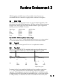
This table shows the default memory segment names and the qualifiers
that correspond to them:
Qualifier
/CSTACK
/CHEAP
/CINIT
Default memory space
DM*
n/a
PM**
Default segment name
seg_stak
no default segment
seg_init
* PM stack is not supported
** seg_init must be in 48-bit program memory
There must be an area of memory named seg_dmda and an area named
seg_pmco to use the C runtime library. Static variable are stored in
seg_dmda .
3.2.1.2 .BANK Directive
The .BANK directive is used to configure your target hardware system
memory. It lets you configure the wait states, page sizes, page modes, and
banks of physical memory. Use the .BANK directive to configure the
physical memory, and the .SEGMENT directive to configure the logical
organization of memory. See the ADSP-21020 User’s Manual or the
ADSP-2106x SHARC User’s Manual for information about how the
processors use external memory banks.
Note: The .BANK directive is not currently supported in ADSP-2106x
systems.
The syntax of the .BANK directive is
.BANK [qualifiers]
where qualifiers is one or more of:
3–4
/WTSTATES=n
(n= 0 to 7 wait states)
/WTMODE=mode
where mode is one of:
INTERNAL
EXTERNAL
EITHER
BOTH
wait for the ADSP-21xxx wait state timer to expire
wait for either the DMACK or PMACK pin to assert
wait for either internal or external
wait for both internal and external
Runtime Environment 3
/PGSIZE = n
n is the number of words to a DRAM page, from 0 to
32768; n must be a power of 2. All PGSIZE values
for DM must be identical and all PGSIZE values for
PM must identical)
/BEGIN=address
Pick one of:
/PM0
/PM1
/DM0
/DM1
/DM2
/DM3
the starting address of this bank
which program memory bank is selected
which data memory bank is selected
Note: Banks DM0 and PM0 must always begin at address 0. The
PGSIZE option need only be applied to one bank each in program
memory and data memory and is necessary only if the PAGE pin is used
for data memory access.
3.2.1.3 .REGISTER/RESERVED Directive
The compiler looks for .REGISTER/RESERVED directives in the
architecture file to determine which registers are reserved.
Note: You can also reserve registers with the -mreserved switch. The
compiler will generate an error if there is more than one -mreserved
switch on the command line, or a single -mreserved switch and a
.REGISTER/RESERVED statement in the architecture file.
3–5
3 Runtime Environment
3.2.1.4 .PROCESSOR= Directive
G21K determines which member of the ADSP-21000 family to generate
an executable for by means of the architecture file
.PROCESSOR = dsp; directive. Legal values for dsp are ADSP21020
and ADSP2106x .
G21K chooses the correct runtime header (either 020_hdr or
060_hdr ) based on the setting of the .PROCESSOR directive of the
architecture file.
G21K invokes the assembler with the –ADSP2106x switch when you
specify the .PROCESSOR = ADSP2106x; directive.
3.2.1.5 Example Architecture File
This is an example of an architecture file for an ADSP-21020 system
using the C runtime environment. The .BANK directive lines shown
put the processor in the same state as the ADSP-21020 processor after a
reset.
.SYSTEM
A_C_System;
.PROCESSOR = ADSP21020;
.SEGMENT /DM /RAM /BEGIN
.SEGMENT /DM /RAM /BEGIN
.SEGMENT /DM /RAM /BEGIN
.SEGMENT /PM /ROM /BEGIN
.SEGMENT /PM /ROM /BEGIN
.SEGMENT /PM /RAM /BEGIN
.SEGMENT /PM /ROM /BEGIN
.SEGMENT /PM /RAM /BEGIN
.BANK /DM0 /PGSIZE = 256
.BANK /DM1 /PGSIZE = 256
.BANK /DM2 /PGSIZE = 256
.BANK /DM3 /PGSIZE = 256
.BANK /PM0 /PGSIZE = 256
.BANK /PM1 /PGSIZE = 256
.ENDSYS;
3–6
= 0x00000001 /END = 0x0000FFFF
seg_dmda;
= 0x00010000 /END = 0x0001FFFF
seg_stak;
= 0x00020000 /END = 0x0002FFFF /CHEAP
heap1;
= 0x000000 /END = 0x0000FF
seg_rth;
= 0x000100 /END = 0x00FFFF
seg_pmco;
= 0x010000 /END = 0x01FFFF
seg_pmda;
= 0x020000 /END = 0x02FFFF
seg_init;
= 0x030000 /END = 0x03FFFF /CHEAP pm_heap1;
/WTSTATES = 7 /WTMODE = BOTH /BEGIN = 0x00000000;
/WTSTATES = 7 /WTMODE = BOTH /BEGIN = 0x20000000;
/WTSTATES = 7 /WTMODE = BOTH /BEGIN = 0x40000000;
/WTSTATES = 7 /WTMODE = BOTH /BEGIN = 0x80000000;
/WTSTATES = 7 /WTMODE = BOTH /BEGIN = 0x000000;
/WTSTATES = 7 /WTMODE = BOTH /BEGIN = 0x800000;
Runtime Environment 3
3.2.2
Variable Storage
The storage class of a variable determines how space is allocated for it in
the C runtime environment.
The optimizing features of G21K may detect that a declared variable is
never actually used by a block of code, and therefore no space is
allocated for it. In general, there is no guarantee where space for any
particular variable is allocated. Do not write assembly language code
that depends on a variable of automatic storage class being at a certain
location.
3.2.3
Runtime Header (Interrupt Table)
A portion of program memory in ADSP-21000 family processors is
used for the interrupt table.
The interrupt table is where the linker puts the code in the runtime
header, 020_hdr.obj or 060_hdr.obj (for the ADSP-21020 and
ADSP-2106x SHARC processors respectively). Unless you disable
automatic linking, a runtime header is linked in by default when you
invoke the compiler. See section 3.2.1.4, “.PROCESSOR=Directive” for
details on how to specify which runtime header is specified in the
architecture file.
The default runtime header is found in the ADI_DSP\21k\lib
directory , with its source file, 0x0_hdr.asm . If the compiler finds a
copy of 0x0_hdr.obj in the current directory, it uses it instead of
the default.
On the ADSP-21020, each interrupt is allocated eight words. On the
ADSP-2106x, each interrupt is allocated four words. C runtime library
functions are provided to simplify interrupt setup and handling. In the
C Runtime Library Manual, see the entries for the interrupt() ,
signal() , and raise() functions.
3–7
3 Runtime Environment
The interrupt vector table is located in the memory segment seg_rth .
You must declare this segment in the architecture file. For example, if the
interrupt table is stored in ROM, include this line in the architecture file:
.segment/rom /begin=0x000000 /end=0x0000ff /pm seg_rth;
The source files 020_hdr.asm and 060_hdr.asm are included in the
software distribution package. If you prefer to write interrupt handlers in
C, use the library functions signal(), raise(), interrupt(), and
their variants based on the runtime header used.
3.2.4
Code Segment
The code segment is where program instructions are stored. It must be in
program memory space.
The code segment begins at the logical location seg_pmco , by default. For
example, to declare a 256 K-word program memory data segment stored in
ROM starting at PM[0x090000], include this line in your architecture file:
.segment/rom /begin=0x090000 /end=0x0cffff /pm
seg_pmco;
To use a code segment other than seg_pmco , declare a program memory
data segment in your architecture file and use –mpmcode compiler
switch.
.segment/rom /begin=0x0d0000 /end=0x0fffff /pm
alt_pmco;
The invocation line for this example is
g21k -mpmcode=alt_pmco myfile.c -a myach.ach
3.2.5
Program Memory Data Segment
The program memory data segment is where static variables in program
memory space are stored. Use the pm qualifier to put C variables in this
segment. For example the C definition statement
static int pm coeffs[10];
allocates an array of 10 integers in the program memory data segment. See
3–8
Runtime Environment 3
Section 5.2 for information on language extensions for dual memory
support.
The program memory data is seg_pmda . For example, to declare a 128Kword program memory data segment starting at PM[0x0d0000], include
this line in your architecture file:
.segment/begin=0x0d0000 /end=0x0effff /pm
seg_pmda;
To use a program memory data segment other than seg_pmda, declare a
program memory data segment in your architecture file and use the
–mpmdata compiler switch. For example,
.segment/begin=0x0d0000 /end=0x0fffff /pm alt_pmda;
3.2.6
Data Memory Data Segment
The data memory data segment is where static variables in data memory
space are stored. You may use the dm qualifier when defining variables;
however if the pm qualifier is not specified, static and global variables are
put in data memory by default. For example,
static int data [10];
allocates an array of 10 integers in the data memory data segment. Usually,
data memory data is physically mapped to RAM.
The data memory data segment is seg_dmda . For example, to declare a
128K-word data memory data segment stored in RAM starting at
DM[0x0d0000], include this line in your architecture file:
.segment/ram /begin=0x0d0000 /end=0x0effff /dm
seg_dmda;
To use a data memory data segment other than seg_dmda , declare a data
memory data segment in your architecture file and use the –mpmdata
3–9
3 Runtime Environment
compiler switch. For example,
.segment/ram /begin=0x0d0000 /end=0x0effff /dm
alt_dmda;
3.2.7
The Runtime Stack
The runtime stack is the storage area for local variables. It is also where
the return address of a calling function is kept.
3.2.7.1 Function Calling Protocol
The C runtime environment uses the runtime stack to store the return
address of the calling function: the calling function pushes the return
address onto the stack.
3.2.7.2 Stack Implementation
The stack is implemented as a 32-bit wide structure, growing from
high memory to low memory.
The stack is managed by a frame pointer and a stack pointer. I6 is used
as the frame pointer and I7 is used as the stack pointer.
A stack frame is a section of the stack used to hold information about
the current context of the C program. The stack frame is where local
and temporary variables reside, as well as parameters that are pushed
onto the stack for the next function. The current stack frame is the stack
space between the frame pointer and the stack pointer.
Note: In general, the first three parameters are stored in registers. See
Chapter 4, Assembly Language Interface, for further details.
The frame pointer serves as a base for accessing memory in the stack
frame. Locals, parameters, and temporaries are referenced by their
offset from the frame pointer.
When a new stack frame is created, the following actions occur:
1. Parameters that are not placed in registers are pushed onto the stack
(with the Stack Pointer advancing).
3 – 10
Runtime Environment 3
2. The Frame Pointer is saved (see “Stack Usage” below).
3. The Frame Pointer is set to the Stack Pointer.
4. The Stack Pointer is advanced to a point beyond local and temporary storage.
When a stack frame is discarded, the following actions occur:
1. The Stack Pointer is set to the Frame Pointer (which is the Stack Pointer of the
previous stack frame).
2. The Frame Pointer is restored to its value for the previous frame (see “Stack
Usage” below).
3. The Stack Pointer is adjusted by the amount it was changed when parameters
were pushed on function entry.
You must define a segment in memory for the runtime stack in your
architecture file. For example, to declare a 4K-word stack called seg_stak
starting at DM[0x070000] , include this line in your architecture file:
.segment/ram /begin=0x070000 /end=0x070fff /dm seg_stak;
3.2.7.3 Stack Usage
The calling function is responsible for loading R2 with the old frame pointer
and loading the new frame pointer with the stack pointer.
1. The calling function loads R2 with the frame pointer and sets the frame
pointer equal the stack pointer.
2. The calling function passes control to the called function using the delayedbranch JUMP (DB) instruction.
3. The calling function pushes the frame pointer in the 1st delayed branch slot.
4. The calling function pushes the return address in the 2nd delayed branch slot.
At the end of the called function:
1. The return address minus one is read off the stack into an index register (I12).
2. The stack pointer is loaded with the frame pointer, the frame pointer is loaded
with the old frame pointer (loaded from the stack).
3. Control is passed back to the calling function by jumping to the return
address plus one.
3 – 11
3 Runtime Environment
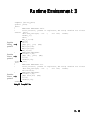
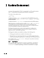
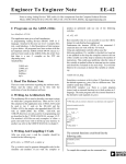
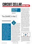
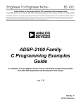
Listing 3.1 shows example C source code, and Listing 3.2 shows the
frame pointer (I6)
High Memo
High Memo
parameter x
paramete
previous frame p
local
local
parameter x
paramete
previous frame p
stack pointer (I7)
frame pointer (I6)
local
local
paramete
previous' frame p
return addr
local0
local1
stack pointer (I7)
Before c
Figure 3.1 Stack Implementation
int
int
int
int
foo(int,int);
x;
c,d,e;
a,b;
main()
{
static int z;
char m;
int w;
z=0;
w=1;
x=foo(a,z);
}
int foo(int x1, int x2)
{
int x3;
x3=(x1+x2)/2;
return x3;
}
3 – 12
Listing 3.1 Example Function
After c
Runtime Environment 3
.segment /pm seg_pmco;
.global _main;
_main:
!
FUNCTION PROLOGUE: main
!
rtrts protocol, params in registers, DM
.extern _exit;
.def end_prologue; .val .;
.scl 109;
r4=dm(_a);
r8=0;
dm(_z_2)=r8;
r2=i6;
i6=i7;
jump (pc, _foo) (DB);
dm(i7,m7)=r2;
dm(i7,m7)=pc;
dm(_x)=r0;
!
FUNCTION EPILOGUE:
i12=dm(-1,i6);
jump (PC, _exit) (DB);
i7=i6;
i6=dm(0,i6);
.global _foo;
_foo:
!
FUNCTION PROLOGUE: foo
!
rtrts protocol, params in registers, DM
.def end_prologue; .val .;
.scl 109;
r0=(r4+r8)/2;
!
FUNCTION EPILOGUE:
i12=dm(-1,i6);
jump (m14,i12) (DB);
i7=i6;
i6=dm(0,i6);
.endseg;
function
calling
protocol
➞
function
return
protocol
➞
function
return
protocol
stack, doubles are floats
.endef;
stack, doubles are floats
.endef;
➞
Listing 3.2 Compiled Code
3 – 13
3 Runtime Environment
resulting assembly code produced by the compiler.
Figure 3.1 shows the configuration of the stack during a typical call.
3.2.7.4 Parameter Passing
Parameters in a function call are passed in registers, if possible. This
decreases the number of cycles it takes to call a function, compared to
pushing parameters onto the runtime stack. See Section 4.2.2,
“Retrieving Parameters” for details.
3.2.7.5 ADSP-2106x Function Calls
The compiler will generate code that uses the CJUMP and RFRAME
instructions for C function calls and returns.
This feature is invoked if the architecture file contains a processor
directive that indicates an ADSP2106x system.
The CJUMP instruction executes three operations at once. Control is
transferred to the specified label, the frame is stored in R2 , and the
frame is loaded with the current stack pointer.
The compiler will generate the following code for function calls:
CJUMP _function_label (DB);
<delay slot 1>;
<delay slot 2>;
The compiler will attempt to fill the two delayed branch slots of
CJUMP with usable instructions (such as ALU or multiplier
operations), otherwise NOPs will be used.
The RFRAME instruction executes two operations at once. The stack
pointer is loaded with the frame pointer, and the frame pointer is
loaded with the old frame (from the stack).
The compiler will use the RFRAME at the end of the function epilogue.
The following code will be generated as the last three instructions of a
function:
JUMP (M14, I13) (DB);
RFRAME;
<delay slot2>;
3 – 14
Runtime Environment 3
The compiler will attempt to fill the available delay slot with a usable
instruction (ALU or multiplier), otherwise a NOP will be inserted.
3.2.8
The Heap
The C runtime library includes four functions, malloc() ,
calloc() , realloc(), and free() to allocate and deallocate
memory dynamically at runtime. The memory for these functions is
taken from a memory segment designated as the heap.
You define a segment in memory for the heap in your architecture file. For example, to
declare a 60 K-word heap called seg_heap starting at DM[0x071000], include this
line in your architecture file:
.segment/ram /begin=0x071000 /end=0x07ffff /dm /cheap
seg_heap;
Note: The architecture file directive /CHEAP is required. It is by this
directive that the linker picks which segment is the heap. This directive is
placed on any number of segments (program or data memory). The
compiler and linker generate the proper code to access the heap. The
logical label you use for the heap segment may be any legal label. (In the
example the name seg_heap was chosen.)
The first segment declared with the /CHEAP directive is the default heap
at program startup. The set_alloc_type() function can be used to
change from which heap memory is allocated. The prototype for this
function is:
int set_alloc_type(char*);
3.2.9
Initialization Segment
The initialization segment is where the system parameters and
initialization information is stored. This information is derived from the
architecture file. It must be in 48-bit program memory space. The size of
the segment varies based on the contents of your architecture file and the
number of global and static initializations.
The initialization segment begins at the logical location seg_init . The
linker uses seg_init to store global and static initialization data. For
example, to declare a 256 word initialization segment stored in ROM
starting at PM[0x090000], include this line in your architecture file:
3 – 15
3 Runtime Environment
.segment/rom /begin=0x090000 /end=0x0900ff /pm
seg_init;
3.3
REGISTERS
All C functions (except functions of type void ) return a value. In the
runtime environment, R0 is the register used to return values that can
fit in one word. If two words are needed (when the function is type
double , for example) R0 and R1 are both used. R0 is the most
significant word and R1 is the least significant word.
If a structure larger than two words is to be returned, the calling
function sets R1 equal to the address where the return structure should
go. The called function copies the result into the area pointed to by R1.
Structures whose size does not exceed two words are returned in
registers R0 and, if necessary, R1 . See Chapter 4, Assembly Language
Interface, for details on return values and other register usage.
3.3.1
Variables In Specified Registers
The compiler supports variables in specified registers with the following
syntax:
register int *foo asm (“R5”);
You may use any of the processor registers with the following
exceptions:
• Do not use the stack registers: B6, I6, M6, L6, B7, I7, M7, L7.
• Do not use the scratch registers: R0, R1, R2, R4, R8, R12, B4, I4, M4, L4,
B12, I12, M12, L12.
• Do not use any of the fixed-value registers: M5, M6, M7, M13, M14, M15.
See the sections “Fixed-Value Registers” and “Saving & Restoring
Registers” in Chapter 4, Assembly Language Interface, for further details.
Exercise extreme caution when using B registers or L registers. These
registers may alter the operation of their associated I registers. See the
“Data Address Generators” chapter of the ADSP-2106x SHARC User’s
Manual or ADSP-21020 User’s Manual for details.
3 – 16
Runtime Environment 3
Global register variables may not have initial values, because an
executable file has no means to supply initial contents for a register.
3.4
DATA TYPES
The ADSP-21xxx family of processors can process 32-bit operands, with
provisions for certain 40-bit operations. All other arithmetic data types are
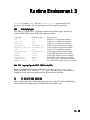
mapped onto these types.The native mode arithmetic types supported
directly are listed in Table 3.1, below.
Data Types
int
float
double*
long
ADSP-21020
32 bits
32 bits
32 bits
32 bits
ADSP-2106x
32 bits
32 bits
32 bits
32 bits
Table 3.1 ADSP-21000 Family Native Mode Data Types
* The -fno-short-double switch causes the the processor to use “no short doubles,”
i.e. it does not default to the use of 32-bit floats. Use this switch for 64-bit doubles.
3.4.1
Type Int
The int type is a fixed-point 32-bit two’s-complement number.
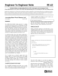
3.4.2
Type Float
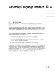
The float type is IEEE-754 standard single-precision floating-point,
implemented in the ADSP-21xxx hardware. It has a 24-bit signedmagnitude fraction and an 8-bit exponent, in the following format:
1 bit
sign bit (s)
31
8 bits
exponent field (e)
...
e0
e7
30
MSB
23
LSB
23 bits
fraction (f)
f22 f21
22
MSB
f0
0
LSB
Implicit binary point
Exponent values for normalized single-precision numbers range from
1 ≤ e ≤ 254, with exponents of 0 and 255 being reserved for special
operands. (Floating-point constants in the range 1e64 – 1e84 will not give
compiler errors but will evaluate to unreliable values. Avoid these ranges
if at all possible.) To calculate the value of a number in this format, the
3 – 17
3 Runtime Environment
exponent is decremented by 127 (the “exponent bias” is +127), and the fraction
has a “1” inserted before the binary point (called the “hidden bit”).
The value of the number is then:
(–1)s 2e-127 (1.f)
Variables declared as double are represented in 32-bit IEEE floating-point
numbers by default. Use the -fno-short-double switch or -ansi switch
for 64-bit numbers.
Variables declared as long double are represented in 64-bit IEEE numbers.
Note: Operations on double-precision numbers ( double and long double )
are calculated with software emulation and do not take advantage of the
hardware floating-point unit—they execute several orders of magnitude more
slowly than operations calculated in single-precision.
Floating-point precision may contain some insignificant rounding errors
because it uses the floating-point format of the host computer. Precision is
improved on a PC with a math coprocessor.
Floating-point numbers are rounded according to the following rules:
• Floating-point numbers are rounded to the nearest value.
• Passing floats to an unprototyped function or a variable argument function
results in promoting those parameters to doubles (per the ANSI specification).
The compiler switch -wfloat-convert alerts you to any silent conversions
between floats and doubles.
3.4.3
Type Complex
The complex type is a Numerical C extension to Standard C. See Chapter 6
for details about the complex type. A complex number is represented as two
float or int numbers, depending on whether it is declared it as complex
3 – 18
Runtime Environment 3
float or complex int . The first float or int represents the real
portion of the number, the second represents the imaginary portion.
3.4.4
Underlying Types
The Table 3.2 lists all the C language arithmetic and data types, and shows
which ADSP-21000 native data types represent them.
C data type
Underlying type
int
int
long int
int
short int
int
unsigned int
unsigned int
unsigned long int unsigned int
char
int
unsigned char
unsigned int
float
float
double
float
long double
double
complex int
int
complex float
float
Representation
32-bit two’s complement number
32-bit two’s complement number
32-bit two’s complement number
32-bit unsigned magnitude number
32-bit unsigned magnitude number
32-bit two’s complement number
32-bit unsigned magnitude number
32-bit IEEE single-precision number
32-bit IEEE double-precision number
64-bit IEEE double-precision number
Two 32-bit two’s complement numbers
Two 32-bit IEEE single-precision numbers
Table 3.2 C Language Types On ADSP-21000 Family DSPs
Note: Some internal compiler mathematics are done in the double type,
while the ADSP-21xxx uses the float type. This may lead to differences in
compiler results between optimized and non-optimized results.
3.5
PC-RELATIVE BRANCHING
The compiler generates all branching instructions with PC-relative addressing
rather than direct addressing. This facilitates relocatable code.
3 – 19
3 Runtime Environment
3 – 20