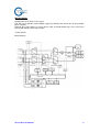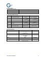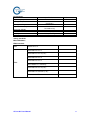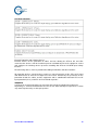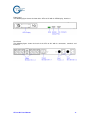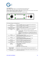
1
ATS-16 HV
Automatic Transfer Switch 16A / 230Vac
USER MANUAL
ATS-16A User Manual rev.1
SAFETY
Intended use
The ATS-16 HV device serves as a power source selector to provide improved power supply
for connected loads.
ATS-16 HV can be operated in the 1 phase mains. The device is in compliance with all
relevant safety regulations concerning information technology equipment, including electronic
machines for use in an office environment.
Warning
The User or Operator may intervene in the operation of the ATS-16 HV provided that the
instructions laid out on below connection.
The Installation of the ATS-16 HV may only be carried out by qualified technical
personnel.
Even when all switches and interrupters are open, hazardous voltages are present within
the ATS-16 HV; any operation that requires cases to be opened and/or removed may be
carried out by authorized technical personnel only.
Safety notices
Danger
Carefully read the following safety notices! Failure to observe the instructions may danger
your life, your health, the reliability of your device or the security of your data.
Transport the unit only in suitable packaging.
If the equipment is moved from a cold environment to the operating room, condensation
may occur. Before you switch on the equipment it must be absolutely dry.
The equipment must be installed in accordance with the environment conditions specified
as, Operating temperature: 0 to 40 , Operation humidity: 20% to 85% (no condensing).
ATS-16 HV devices are not intended to operate with isolated neutral. Neutral connector
must be present.
Lay all cables so that nobody can stand on them or trip over them.
For pluggable equipment, the socket-outlet shall be installed near the equipment and
shall be easily accessible. The plug on the power supply cord is intended to serve as the
disconnecting device.
Make sure that no objects get inside the device.
ATS-16 HV User Manual
2
Do NOT connect equipment that will overload the ATS-16 HV. (for example: laser
printers).
The sum of the leakage currents of the ATS-16 HV does not exceed 3.5mA. Earth
connection is essential for ATS-16 HV before connection supply.
Data transmission lines should NOT be connected or disconnected during a
thunderstorm.
Emergency
Danger
The supply to the load may be interrupted by opening all the switches.
DO NOT use WATER to extinguish any fires that may occur in the area in which the ATS-16
HV is installed.
Radio Interference
The ATS-16 HV is a Radio Interference Class C1 product (IEC62310-2).
The device may cause radio interference. DO NOT place it near devices which are especially
susceptible to electromagnetically interference.
Repackaging
DO NOT remove air from the packaging.
ATS-16 HV User Manual
3
OPERATING INSTRUCTIONS
Introduction
This manual contains information regarding the installation, operation and use of the ATS-16
HV.
It is advised that this User Manual be consulted before installation of the equipment, which
operation shall only be carried out by qualified personnel.
Device Overview
The ATS-16 HV is available voltage level 220/230/240Vac,
Nominal current: 16Amp.
PREPARATION FOR USE
Delivery and Storage
The goods have been checked thoroughly before dispatch. On receipt check the packaging
and ensure that the contents are undamaged. Any damage or missing parts must be reported
to the supplier as soon as possible.
Inventory List
ATS-16 HV module
2 pluggable input power cable (p/n: 108-00140-xx)
Bracket kits (for rack mounting and vertical mounting)
NOTE:
㎜
2
must be used.
1. An approved power cord greater or equal to H05VV-F, 3G, 0.75
2. User Manual will be file sending only, not make printing and put it in accessory kit.
Storage
Storage temperature:-25 to 70 ,
Storage humidity: from 10% to 90%.
Handling
The equipment must be handled with care, damage may be caused if dropped or subjected to
severe impact.
Environmental Conditions
The ATS-16 HV must be installed as rack mount or on a level and even surface and in an
area protected from extremes of temperature, water and humidity and the presence of
conductive powder or dust.
DO NOT stack units and do not place any objects on top of a unit.
Rack Mounting
Taking into consideration to mount the ATS-16 HV into a cabinet, it is necessary that chosen
cabinet be capable of supporting the unit with corresponding rails or angels.
ATS-16 HV scope of supply contains two angels for fixing the ATS-16 HV into a 19 inch rack
or into a cabinet with 19 inch inner design.
Also ATS-16 HV vertical mounting is possible.
ATS-16 HV User Manual
4
Dimensions of area
It is necessary to leave a minimum space of a few centimeters around right side, left side and
rear side to allow a flow of air and to provide access to interface.
ATS-16 HV User Manual
5
INSTALLATION
Configuration of the ATS-16 HV system
The ATS-16 HV provides high reliability supply by switching the load to one of two possible
power suppliers.
Primarily these two supplies are UPS devices with sinusoidal output only. These UPS must
operate with double conversion principle.
Technical Data
Block Diagram
ATS-16 HV User Manual
6
ATS-16 HV Technical Data
Input features
Item
Nominal input voltages
Working range
Specification
230 Volts
(220/230/240 selectable)
160 ~ 290Vac
Input voltage acceptance
window
Input voltage low comeback
Nominal voltage
+/- 12% ~ +/- 20%
Input voltage low loss volts +10V
Input voltage high comeback
Input voltage high loss volts -10V
Nominal current
Nominal frequency
Input frequency range
Output features
Items
Output voltage
Output frequency
Output current
Typical transfer time
Max. transfer time
Remark
Default: 230Vac
Adjustable
(Default: +/- 12%)
16 Amp
50/60Hz selectable
Nominal frequency +/- 15%.
Specifications
Same as input voltage
Same as input (50 /60 Hz)
16 Amps
<10ms
15m second
Remark
Specifications
IEC 320-C20x 2
Remark
Power Cord: p/n
108-00140-xx
Interface
Items
Inlet
Outlet
EPO active
ATS-16 HV User Manual
IEC 320-C19 x 1
IEC 320-C13-3 x2
Output NOT supplied.
7
Communications:
A. RS232 (DB-9, pin type)
PIN No.
PIN 2:
Definition
RX
PIN 3:
PIN 5:
TX
GND
B. Dry Contact (DB-9, pin type)
Pin No.
Description
Open State
Close State
Normal
Over Temperature
Source 1 is fail
Source 1 is ok
Normal
Over load
Pin 1
Over temperature signal
Pin 2
Not used
Pin 3
Not used
Pin 4
Source 1 status signal
Pin 5
Common
Pin 6
Not used
Pin 7
Over load signal
Pin 8
Source 2 status signal
Source 2 is fail
Source 2 is ok
Pin 9
Summary alarm signal
Normal
Alarm occurred
Mechanical Features
Items
Dimension
Weight
Packaging sizes
Color
Material
Structure
ATS-16 HV User Manual
Specification
W = 430mm
D = 315mm
H = 44mm (1U)
Approx. 8kg
W = 585mm
D = 425mm
H = 184mm
Remark
Silver
RAL 9006
Metallic Case
Rack Mount Unit (1U)
Vertical mount (0U)
8
Environment
Items
Operating temperature
Storage temperature
Storage humidity
Operation humidity
Operation Altitude
Audible noise
Cooling
IP Protection
Specifications
0 to 40 °C
-25 °C to 70 °C
Continuous
10% to 90%
20%to 85%
No condensing
≤ 1000m
25dBA (max.)
Natural Cooling
IP 30
Comments
Buzzer OFF
Safety Standards
Meet IEC60950-1.
EMC Standard:
EMI
IEC62310-2, C1
IEC61000-4-2 level 3
IEC61000-4-3 level 2 (Lab.)
IEC61000-4-4 level 2
IEC61000-4-5 level 3
EMS
IEC 61000-2-2 LF Immunity
IEC61000-4-6 level 2 (Lab.)
IEC61000-3-2 Harmonic (Lab.)
IEC61000-3-3 Flicks
ATS-16 HV User Manual
9
Overload Capability:
External Protection and Isolation Devices
External devices for the protection of cables and for isolating the ATS-16 HV and UPS
external to the devices shall be installed upstream and downstream of the equipment. Select
and configure the isolating device upstream according with ATS-16 HV MCB input 16Amp
breakers.
Disconnecting devices must be provided in building installations and other locations.
All protection devices (circuit breakers and fuses) placed upstream of the ATS-16 HV input
and downstream to ATS-16 HV output line have to be installed by the personnel for the
protection of both the cables and the equipment and in coordination with both ATS-16 HV
input protection (fuses) and ATS-16 HV overload capacities.
WARNING
If ATS-16 HV overload capacities are overcome the unit will unsupplied the output load.
Depending on overload characteristic the ATS-16 HV either will trip the input fuses or drive
only internal power relays to the open position.
ATS-16 HV User Manual
10
Front Panel
The following figure shows the front of the ATS-16 HV with its LED display, interfaces.
Rear Panel
The following figure shows the back of the ATS-16 HV with its connectors, terminals and
interfaces.
ATS-16 HV User Manual
11
Operating Panel
In the following figure you can see the front panel of the ATS-16 HV.
Most functions of the ATS-16 HV are driven by an internal control.
From the operating panel a priority setting can be made to prefer a mains source. The state of
the relay group is displayed with several LEDs.
Please see more detail operation information in following table.
ATS-16 HV User Manual
12
Description of the system
The 2-pole ATS-16 HV is a two ways, single phase automatic switch powered by two
independent synchronous or asynchronous AC power supply sources.
The ATS-16 HV makes a rapid switch from one source to the other in the event of a fault to
the power supply used to power the load.
One of the two sources can be designated as the preferred power supply, to which the
ATS-16 HV will transfer the load. It remains there until different designations or faults require
it to be switched to the other source.
The ATS-16 HV is fitted with a block diagram with LED indicators, capable of providing all
information concerning equipment operation status, together with the power source priority
selection button BP2 enable trained operators to make full use of the apparatus.
Features:
- Break Before Make transfer mode.
- Back feed protection (according EN62310-1).
- Complete protection for overload and short-circuit. (With FUSE Holder Accessible).
- Redundant power supply. (From input Source 1 and Source 2).
- AC source detection (voltage and current detection).
- Output detection (current detection).
- LED display.
- EPO contact is integrated
- Different setting to adjust the voltage failure sensing level (+/- 12% ~ +/- 20%). (Default
setting: Nominal voltage +/- 12%).
- Protection: IP30.
- ON/OFF for Buzzer
- Selectable Nominal Frequency
- RPO active (open): output not supplied.
ATS-16 HV User Manual
13
Manual Switch ON Procedures
First Switch on from Source A
Check that all switches are OFF and check the EPO status.
Input the mains for source A.
Wait for several seconds until the logic is enabled and the LEDs on the display are
switched ON.
- Priority LED PS1 or PS2 depending on the default setting.
- LED S1
- LED SW1
Input the mains for source B.
The following LEDs are illuminated:
- Priority LED PS1 or PS2 depending on the default setting.
- LED S1
- LED S2
- LED SW1 or SW2 according to the primary source
First Switch on from Source B
Check that all switches are OFF and check the EPO status.
Input the mains for source B.
Wait for several seconds until the logic is enabled and the LEDs on the display are
switched ON.
- Priority LED PS1 or PS2 depending on the default setting.
- LED S2
- LED SW2
Input the mains for source A.
The following LEDs are illuminated:
- Priority LED PS1 or PS2 depending on the default setting.
- LED S1
- LED S2
- LED SW1 or SW2 according to the primary source
Switch OFF
Warning
When this procedure is carried out the load is no longer supplied by the ATS-16 HV.
ATS-16 HV User Manual
14
Troubleshooting
If problems should occur, please check the following points before contacting the responsible
customer service representative:
Is the mains voltage present at the ATS-16 HV input?
Has one of the two input fuses tripped or open?
If you contact the responsible customer service representative, please have the following
information ready:
Device information (model name and serial number)
An exact description of the problem (what loads are being operated, does the problem
occur regularly or sporadically, etc.)
Rectification of errors:
Problem
No display, no alarm.
Both mains indicator S1 and
S2 do not illuminate, when
mains voltage present.
Possible Cause
Mains or feeding UPS units
switched off.
Switch on the mains or
feeding UPS units.
No mains voltage present.
Have mains inspected by
qualified electrician.
Input fuses tripped.
Check and make sure the
load capacity within the
specification, then replace a
good fuse. If the problem
persists, contact the
responsible customer service
representative.
Check and make sure the
load capacity within the
specification, then replace a
good fuse. If the problem
persists, contact the
responsible customer service
representative.
Contact the responsible
customer service
representative.
Both input fuses tripped.
Alarm indicator F1 illuminates, ATS-16 HV Fault.
acoustic alarm active with 0.5
second sequence.
ATS-16 HV User Manual
Measure
EPO
Check all loads and solve
(clear) the problem that
caused the EPO.
Overheating
Check and make sure the
load capacity within the
specification, or decrease
ambient temperature (less
than 40 ).
15
Service Address
G-Tec Europe srl
Registered office:
Corso Palladio 147
36100 Vicenza
Tel. +39 0444 592463
Fax +39 0444 365191
Mailing Office/H.Q.:
Strada Marosticana 81/25
36031 Povolaro (VI)
E-mail: [email protected]
ATS-16 HV User Manual
16