1
INSTRUCTION MANUAL (ATEX / IECEx)
BExDTS110D Flameproof Sontel
For use in Flammable Gas and Dust Atmospheres
1)
3) Type Approval Standards
Introduction
The BExDTS110D is a flameproof Sontel telephone sounder
which is certified to meet the requirements of the ATEX
directive 94/9/EC and IECEx scheme. The Sontel produces a
loud audible signal when triggered by a telephone ringing
signal and can be used in hazardous areas where potentially
flammable gas and dust atmospheres may be present. Thirtytwo different sounds can be selected by internal switches (see
tone table on Page 4). The BExDTS110D unit produces
output levels in the 110dB(A) range. The unit can be used in
Zone 1 and Zone 2 areas with gases in groups IIA, IIB and IIC
and temperature Classifications of T1, T2, T3 and T4. For
ambient temperatures over +55ºC the gas groups are limited to
IIA and IIB. They can also be used in Zone 21 and Zone 22
areas for combustible dusts and have an IP rating of IP 67 and
a surface temperature rating of T100ºC up to +55ºC and
T115ºC over +55ºC.
2)
Marking
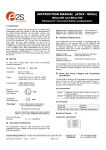
All units have a rating label, which carries the following
important information:Unit Type No.
BExDTS110D
Input Voltage:
DC Units:
AC Units:
12V or 24V or 48V
230V or 110V or 115V
Ex d IIC T4 for Ta –50°C to +55°C
Ex d IIB T4 for Ta –50°C to +70°C
Ex tD A21 IP67 T115°C based on max Ta of +70°C
Codes:
KEMA 99ATEX6312
IECEx KEM 10.0003
Certificate No’s
Epsilon x:
Equipment Group and
Category:
II 2G/D
The Sontel has EC Type Examination and IECEx certificates
issued by KEMA and has been approved to the following
standards:EN60079-0:2006 IEC60079-0:2004 (Ed4)
EN60079-1:2007 IEC60079-1:2007 (Ed6)
EN61241-0:2006 IEC61241-0:2004 (Ed1)
EN61241-1:2004 IEC60079-1:2004 (Ed1)
0518
Dust General
Requirements
Dust Enclosures tD
4) Installation Requirements
The Sontels must be installed in accordance with the latest
issues of the relevant parts of the EN 60079 standards or the
equivalent IEC standards – Selection, Installation and
maintenance of electrical apparatus for use in potentially
explosive atmospheres (other than mining applications or
explosive processing and manufacture):EN60079-14:2008
IEC60079-14:2007 (Ed4)
EN60079-10:2003
IEC60079-10:2008 (Ed1)
Electrical Installations in Hazardous
Areas (other than mines)
Classification of Hazardous Areas
The installation of the units must also be in accordance with
any local codes that may apply and should only be carried out
by a competent electrical engineer who has the necessary
training.
5) Zones, Gas Group, Category, IP Rating and
Temperature Classification
The BExDTS110D Sontels have been certified Ex d IIC T4 for
Ta –50°C to +55ºC and Ex d IIB T4 for Ta –50°C to +70ºC for
gas and Ex tD A21 IP67 T115ºC based on max. Ta of +70ºC
for dust. This means that the units can be installed in locations
with the following conditions:Area Classification Gas:
Zone 1
CE Marking
Notified Body No.
General Requirements
Flameproof Enclosure ‘d’
Zone 2
Explosive gas air mixture likely to occur in
normal operation.
Explosive gas air mixture not likely to occur,
and if it does, it will only exist for a short time.
Gas Groupings:
“Warnings”
DO NOT OPEN WHEN AN EXPLOSIVE
GAS OR DUST ATMOSPHERE IS PRESENT
COVER BOLTS CLASS A4-80
USE HEAT RESISTING CABLES AND CABLE GLANDS
(Rated 110ºC) AT AMB. TEMPERATURES OVER 40ºC
Year of Construction /
Serial No.
i.e. 10 / 1DTS23000001
Group IIA
Group IIB
Group IIC (Up to +55ºC only)
Propane
Ethylene
Hydrogen and Acetylene
Temperature Classification:
T1
T2
T3
T4
400 o C
300 o C
200 o C
135 o C
__________________________________________________________________________________________________________________________________
European Safety Systems Ltd. Impress House, Mansell Road, Acton, London W3 7QH
[email protected]
Tel: +44 (0)208 743 8880
www.e-2-s.com
Fax: +44 (0)208 740 4200
Document No. IS 2457-P
Issue E
12-03-10
Sheet 1 of 4
4 off M6 Cover Screws
Area Classification Dust:
Zone 21
Zone 22
IP Rating:
Explosive dust air mixture likely to occur in
normal operation.
Explosive dust air mixture not likely to occur,
and if it does, it will only exist for a short time.
T100ºC Ta < +55ºC
T115ºC Ta < +70ºC
IP67
Equipment Category:
External Earth
Terminal
2G/D
Ambient Temperature Range:
Figure 2
-50°C to +55°C Gas Groups IIA, IIB and IIC
-50°C to +70°C Gas Group IIA and IIB
6) Sontel Location and Mounting
The location of the Sontels should be made with due regard to
the area over which the warning signal must be audible. And
they should only be fixed to services that can carry the weight
of the unit.
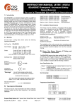
The Sontels should be securely bolted to a suitable surface
using the 7mm diameter boltholes in the stainless steel U
shaped mounting bracket (see figure 1). The angle can then be
adjusted in the direction that the sound is primarily required to
cover. This can be achieved by loosening the two large bracket
screws in the side of the unit, which allow adjustment in steps
of 18°. On completion of the installation the two large bracket
adjustment screws on the side of the unit must be fully
tightened to ensure that the unit cannot move in service.
Flameproof
Chamber
Flameproof
Cover
On completion of the cable wiring installation the flameproof
joints should be inspected to ensure that they are clean and
that they have not been damaged during installation. Also
check that the earth bonding wire between the two casting
sections is secure and the ‘O’ ring seal is in place. W hen
replacing the flameproof cover casting ensure that it is square
with the flameproof chamber casting before inserting. Carefully
push the cover in place allowing time for the air to be expelled.
Only after the cover is fully in place should the four M6
Stainless Steel A4-80 cover bolts and their spring washer be
inserted and tightened down. If the cover jams while it is being
inserted, carefully remove it and try again. Never use the cover
bolts to force the cover into position.
8) Power Supply Selection
It is important that a suitable power supply is used to run the
Sontels.
The following table shows the input current taken by the
various units:-
Plastic Acoustic Horn
(Anti-static Plastic)
Figure 1
Note the four M6 screws are Class A4-80 stainless steel
and only screws of this category can be used on these
Sontels. It is therefore important that these screws and their
spring washers are kept in a safe place during installation.
S/S Mounting
Bracket
7) Access to the Flameproof Enclosure
In order to connect the electrical supply cable and the
telephone line cable to the Sontel it is necessary to remove the
flameproof cover to gain access to the flameproof chamber.
To achieve this remove the four M6 hexagon socket head
screws (see figure 2) and withdraw the flameproof cover taking
extreme care not to damage the flameproof joints in the
process.
Unit Type
Input
Voltage
Input
Current
Max.
I/P Volts
BExDTS110D
BExDTS110D
BExDTS110D
BExDTS110D
BExDTS110D
BExDTS110D
24V DC
12V DC
48V DC
230V AC
110V AC
115V AC
265mA
195mA
130mA
56mA
93mA
110mA
30V
15V
58V
264V
121V
126V
The input current will vary according to the voltage input level
and the frequency of the tone selected. The current levels
shown above are for the 440Hz Continuous tone @ nominal
input voltage. The units have a switching voltage regulator
circuit and therefore the input current level will decrease
slightly as the input voltage in increased and will increase
slightly as the input voltage is reduced.
The above table also shows the maximum voltages at which
the sontels can be operated.
__________________________________________________________________________________________________________________________________
European Safety Systems Ltd. Impress House, Mansell Road, Acton, London W3 7QH
[email protected]
Tel: +44 (0)20 8743 8880
www.e-2-s.com
Fax: +44 (0)20 8740 4200
Document No. IS 2457-P Issue E
12-03-10
Sheet 2 of 4
9)
Cable Selection
W hen selecting the cable size consideration must be given to
the input current that each unit draws (see table above), and
the length of the cable runs.
SAFETY WARNING: If the high output BExDTS110D units are
used at high ambient temperatures, i.e. over +40ºC, then the
cable entry temperature may exceed +70ºC and therefore
suitable heat resisting cables must be used, with a rated
service temperature of at least 110ºC.
10) Earthing
The Sontel units must be connected to a good quality earth.
The units are provided with internal and external earthing
terminals which are both located on the terminal chamber
section of the unit (see figures 2 and 3).
Internal Bonding
Wire Terminal
2 off M20
Cable Entries
Internal Earth Terminal
Figure 3
W hen using the internal earth terminal ensure that the
stainless steel M4 flat washer is between the incoming earth
wire and the enclosure.
W hen using the internal earth terminal ensure that the
stainless steel M4 flat washer is between the incoming earth
wire and the enclosure.
W hen only one cable entry is used the other one must be
closed with an Ex ‘d’ flameproof blanking plug, which must be
suitably approved for the installation requirements.
For combustible dust applications, the cable entry device and
blanking elements shall be in type of explosion protection
increased safety "e" or flameproof enclosure "d" and shall have
an IP 6X rating according to EN 60529.
SAFETY WARNING: If the BExDTS110D Sontels are used at
high ambient temperatures, i.e. over +40ºC, then the cable
entry temperature may exceed +70ºC and therefore suitable
heat resisting cable glands must be used, with a rated service
temperature of at least 110ºC.
12) Cable Connections
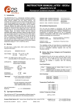
The cable connections are made into the terminal blocks on
the Sontel pcb assembly located in the flameproof enclosure.
See section 7 of this manual for access to the flameproof
enclosure. The printed circuit board has two terminal blocks;
one for the power supply input voltage and one for the
telephone signal input cable (see figures 4 and 5). The power
input cable should enter the enclosure via one of the M20
cable entries and be connected to the supply terminals (L and
N) AC units (+ve and –ve) DC units and the telephone signal
cable should enter the enclosure via the other M20 entry and
be connected to the telephone terminal.
A single wire with a cross sectional area of up to 4mm² can be
connected to each terminal way. W hen connecting wires to the
terminals great care should be taken to dress the wire so that
when the cover is inserted into the chamber the wires do not
exert excess pressure on the terminal blocks. This is
particularly important when using cables with large cross
sectional areas such as 2.5mm² and above.
BExDTS110D AC Sontels
Volume Control
Pulse Tone
Header Pin
DIP Switch
W hen using the external earth terminal a cable crimp lug must
be used. The cable lug should be located between the two M5
stainless steel flat washers. The M5 stainless steel spring
washer must be fixed between the outer flat washer and the
M5 stainless steel nut to ensure that the cable lug is secured
against loosening and twisting.
The internal earth bonding wire ensures that a good quality
earth is maintained between the flameproof chamber casting
and the flameproof cover casting.
Telephone Signal
Input Terminals
Mains Supply
Input Terminals
L and N
Figure 4
11) Cable Glands
The BExDTS110D Sontels have dual cable gland entries
which have an M20 x 1.5 as standard. Only cable glands
approved for Ex ‘d’ applications can be used, which must be
suitable for the type of cable being used and also meet the
requirements of the Ex ‘d’ flameproof installation standard
EN60079-14:2008 / IEC60079-14:2007.
__________________________________________________________________________________________________________________________________
European Safety Systems Ltd. Impress House, Mansell Road, Acton, London W3 7QH
[email protected]
Tel: +44 (0)20 8743 8880
www.e-2-s.com
Fax: +44 (0)20 8740 4200
Document No. IS 2457-P Issue E
12-03-10
Sheet 3 of 4
BExDTS110D DC Sontels
Volume Control
DIP Switch
Terminal block
not used
TONE SELECTION TABLE
Note Switch No. 6 is not used
Telephone Signal
Input Terminals
Tone Selection
Stage 1
1
Pulse Tone
Header Pin
DC Power Supply
Input Terminals
+ve and -ve
Figure 5
13) Tone Selection
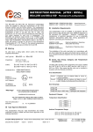
The BExDTS110D Sontels have 32 different tones that can be
selected by the DIP switches on the sounder pcb (see figures
4 and 5). The tone table on page four shows the switch
positions for the 32 tones.
14) Pulse Tone Operation
The BExDTS110D Sontel has two modes of operation
continuous tone operation and pulsed tone operation. To
select continuous tone operation the pulse tone header pins
should not be shorted (see figures 4 and 5). In this mode the
output tone will be as per the tone table. To select pulse tone
operation the pulse tone header pins should be shorted (see
figures 4 and 5). In this mode of operation the selected tone
pattern will pulse on and off following the telephone input
signal. Note if pulsed tone operation is selected it is advisable
not to select any of the intermittent tones, such as tone 11.
15) Volume Control
2
3
4
5
6
7
8
9
10
11
12
13
14
15
16
17
18
19
20
21
22
23
24
25
26
27
28
29
30
31
32
DIP Switch
Settings
Frequency Description
1 2 3 4 5
Continuous 1000Hz
Toxic gas alarm
Alternating 800/1000Hz at 0.25s
intervals
Slow Whoop 500/1200Hz at 0.3Hz
with 0.5s gap repeated
Sweeping 800/1000 at 1Hz
Continuous at 2400Hz
Sweeping 2400/2900Hz at 7Hz
Sweeping 2400/2900Hz at 1Hz
Siren 500/1200/500Hz at 0.3Hz
Sawtooth 1200/500Hz at 1Hz
Alternating 2400/2900Hz at 2Hz
Intermittent 1000Hz at 0.5Hz
General alarm
Alternating 800/1000Hz at 0.875Hz
Intermittent 2400Hz at 1Hz
Intermittent 800Hz 0.25s on 1s off
Continuous at 800Hz
Intermittent 660Hz 150mS on,
150mS off
Alternating 544Hz
(100mS)/440Hz(400mS)
Intermittent 660Hz 1.8s on, 1.8s off
1400Hz to 1600Hz sweep up over
1s - 1600Hz to 1400Hz sweep down
over 0.5s
Continuous 660Hz
Alternating 554/440Hz at 1Hz
Intermittent 554Hz at 0.875Hz
800Hz pulsing at 2Hz
Sweeping 800/1000Hz at 50Hz
Sweeping 2400/2900Hz at 50Hz
Simulated bell sound
Continuous 554Hz
Continuous 440Hz
Sweeping 800/1000Hz at 7Hz
420Hz repeating 0.625s on, 0.625s
off Australian alert signal
1200/500Hz at 1 Hz
Prepare to abandon platform
Sweeping 500/1200Hz 3.75s on,
0.25s off 15Hz
0 0 0 0 0
1 0 0 0 0
0 1 0 0 0
1
0
1
0
1
0
1
0
1
0
0
1
1
0
0
1
0
1
1
1
1
0
0
0
0
0
0
0
0
1
1
1
0
0
0
0
0
0
0
0
1
0
1
0
1
1
0
0
1
1
0
1
1
1
1
1
1
1
1
1
0
0
0
0
0
0 0 0 0 1
1 0 0 0 1
0 1 0 0 1
1
0
1
0
1
0
1
0
1
0
1
1
0
0
1
1
0
0
1
1
0
0
0
1
1
1
1
0
0
0
0
1
1
0
0
0
0
0
1
1
1
1
1
1
1
1
1
1
1
1
1
1
1
1
1
0 1 1 1 1
1 1 1 1 1
The BExDTS110D Sontel has a volume control to adjust the
output level. To set the required output level, adjust the
potentiometer on the sontel pcb (see figure 4). For maximum
output level the potentiometer should be set to the fully
clockwise position.
__________________________________________________________________________________________________________________________________
European Safety Systems Ltd. Impress House, Mansell Road, Acton, London W3 7QH
[email protected]
Tel: +44 (0)20 8743 8880
www.e-2-s.com
Fax: +44 (0)20 8740 4200
Document No. IS 2457-P Issue E
12-03-10
Sheet 4 of 4
EC DECLARATION OF CONFORMITY
Manufacturer:
European Safety Systems Ltd.
Impress House, Mansell Road, Acton
London, W3 7QH, UK
Equipment Type:
BExS110D, BExS120D, BExS110E, BExS120E,
BExDS120D, BExDS110D, BExDS120E, BExDS110E,
BExL25D, BExL15D, BExL25E, BExL15E,
BExDL25D, BExDL15D, BExDL25E, BExDL15E,
BExA110D, BExA120D, BExA110E, BExA120E,
BExDA110D, BExDA120D, BExDA110E, BExDA120E,
BExTS110D, BExDTS110D, BExH120D, BExDH120D, BExL25GD, BExDL25GD
Directive 94/9/EC: Electrical and Mechanical equipment for use in explosive atmospheres (ATEX)
Notified Body for EC type Examination:
KEMA Quality B.V.
Notified Body No.: 0344
Utrechtseweg 310, 6812 AR Arnhem, The Netherlands
EC-type Examination Certificate:
KEMA 99ATEX6312
Notified Body for Quality Assurance Notification:
Sira Certification Service
Notified Body No.: 0518
Rake Lane, Eccleston, Chester CH4 9JN, UK
Quality Assurance Notification:
SIRA 05 ATEX M342
Provisions fulfilled by the equipment:
ll2 G Ex d llB or llC T4 or
ll2 G Ex de llB or llC T4
ll2 D Ex tD A21 lP66 or lP67 T100 °C or T115 °C
Standards applied:
EN 60079-0:2006
EN 60079-1:2007
EN 60079-7:2003
EN 61241-0:2006
EN 61241-1:2004
Directive 89/106/EEC: Construction Products Directive (CPD) – BExS110D24DC / BExS120D24DC (tones 2, 3, 9, 15, 16, 17) only
Notified Body for EC type Examination:
VdS Schadensverhütung GmbH
Notified Body No.: 0786
Amsterdamer Str 172-174, 50735 Köln, Germany
EC-type Examination Certificate:
0708-CPD-20225
Standards applied:
EN 54-3:2001 + A1:2002
Directive 2009/26/EC: Marine Equipment Directive (MED) – BExS110D24DC-M only
Notified Body for EC type Examination:
Germanischer Lloyd SE
Notified Body No.: 0098
Brooktorkai 18, 20457 Hamburg, Germany
EC-type Examination Certificate:
19 702 - 11 HH
Standards applied:
EN 54-3:2001 + A1:2002 + A2:2006
IEC 60092-504: 2001
IEC 60533: 1999
Directive 2004/108/EC: Electromagnetic Compatibility Directive (EMC)
Standards applied:
EN 61000-6-1:2007
EN 61000-6-2:2005
EN 61000-6-3:2007
EN 61000-6-4:2007
The standards EN 60079-0: 2006, EN 60079-7:2003, EN 61241-0:2006 and EN 61241-1:2004 are no longer harmonized. The
requirements of these standards have been checked against the harmonized standards EN 60079-0:2009, EN 60079-7:2007 and EN
60079-31:2009 and there were no major technical changes affecting the latest technical knowledge for the products listed above.
On behalf of European Safety Systems Ltd., I declare that, on the date the equipment accompanied by this declaration is placed on the
market, the equipment conforms with all technical and regulatory requirements of the above listed directives.
Martin Streetz
Quality Assurance Manager
Telephone: +44 (0)20 8743 8880
Facsimile: +44 (0)20 8740 4200
E-mail: [email protected]
www.e2s.com
Date and Place of Issue: London, 04/07/2012
Document No:
DC-001-Issue_C
European Safety Systems Ltd
Company Registration No. 2763350
Registered Office: Impress House
Mansell Road, London, UK, W3 7QH, UK