1
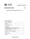
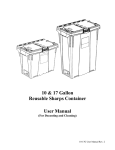
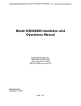
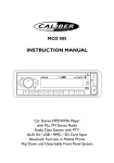
Model PRESET 8
Installation and Operations Manual
Doug Fleenor Design, Inc.
396 Corbett Canyon Road
Arroyo Grande, CA 93420
(805) 481-9599 Voice and FAX
Manual revision
March 2, 2015
Page 1 of 7
Product description
The Preset 8 is a lighting control station that stores eight preset looks. Each look, or scene, has an
associated slider that adjusts the light levels for that look. The preset looks are recorded into the
Preset 8 by capturing the output of any DMX512 console.
Preset 8 systems may consist of single or multiple stations. Systems with multiple stations utilize a
Main/Remote concept in that the looks are recorded into the Main stations with the remote stations
controlling some, or all, of the levels.
Environmental
Operating temperature: 0-40º C
Operating humidity: 10-90% non-condensing
Indoor use only
Electrical ratings
Input: 12-24 volts AC or DC, 100 mA maximum
A common “doorbell” transformer can be used as a power source. The Doug Fleenor Design model
XFMR can be used to power up to four Preset 8 stations.
System layout
Cabling used for DMX512 signals to and from the Preset 8 stations must be specified for DMX512
usage. Examples include Belden 9829 and Belden 9729 or their equal.
Low voltage power cabling for the Preset 8 may be run in the same conduit with the DMX512 cabling.
Doug Fleenor Design suggests using #16 AWG wire for station power cabling.
5
4
3
2
1
3
2
1
Page 2 of 7
1
2
1
2
1
2
1
2
1
2
1
2
General notes:
Preset 8 stations must be connected to one another on the input or “upstream” side of DMX splitters
or processing devices. All DMX cabling must be installed in a “daisy chain” or “touch-and-go” wiring
fashion. DMX cabling using “star”, “T”, or “Y” configurations will result in unreliable operation.
Station power cabling may be wired using any topology that is convenient. However, it is usually
most convenient to run the low voltage power cabling along with the DMX cabling.
Doug Fleenor Design recommends against using the “spare” pair of wire in many DMX cables to
carry power to the Preset 8 stations. The wire gauge is inadequate to prevent excessive voltage
drop. Unreliable operation may result from this practice.
Main station wiring:
The DMX signal from a control console must be connected to the three pin DMX IN terminal block
(TB2).
The DMX output signal from the Preset 8 is available on the five pin terminal block (TB1). The
common, data plus, and data minus signals
Input power to the station should also be connected to this terminal block. The POWER COMMON
and 12-24V AC/DC terminals are used for power input to the Preset 8 stations. Take care to observe
proper polarity when connecting DC power to the Preset 8. A low voltage AC source can be used to
power the Preset 8. The low voltage AC power must be within the range of 12 – 24V. Note that if a
single transformer is used to power multiple stations, all stations must be wired with the same
polarity. It does not matter which wire from the transformer is connected to the C terminal, but the
same wire must be connected at all stations. Failure to observe proper polarity may result in a
damaged transformer which will not be covered by any warranty.
IMPORTANT NOTE: DO NOT APPLY 120VAC POWER TO THE PRESET 8. THE STATION WILL
BE DAMAGED BEYOND REPAIR AND WILL NOT BE COVERED BY ANY WARRANTY.
Remote station wiring:
All DMX cabling to and from a Preset 8 Remote station must be connected to the five pin terminal
block (TB1). The cable from the prior station and the cable going out to the next station (or other
DMX devices) will be connected to the same terminals on the five pin terminal block (TB1). The three
pin terminal block (TB2) is not used by Remote stations. No cables are to be connected to the
three pin terminal block (TB2) if the station is configured as a Remote station.
Remote stations may be connected to the Main station input or output connectors. The Main station
supports Remote stations on both its input and output ports simultaneously. However, only a total of
four Remote stations are supported. Each Remote station must have its own unique ID (described
later in this document) regardless of which Main station port it is connected to.
Input power to the station must be connected to the five pin terminal block. The POWER COMMON
and 12-24V AC/DC terminals are used for power input to the Preset 8 stations. Take care to observe
proper polarity when connecting DC power to the Preset 8. A low voltage AC source can be used to
power the Preset 8. The low voltage AC power must be within the range of 12 – 24V. Note that if a
single transformer is used to power multiple stations, all stations must be wired with the same
polarity. It does not matter which wire from the transformer is connected to the C terminal, but the
same wire must be connected at all stations. Failure to observe proper polarity may result in a
damaged transformer which will not be covered by any warranty.
Page 3 of 7
IMPORTANT NOTE: DO NOT APPLY 120VAC POWER TO THE PRESET 8. THE STATION WILL
BE DAMAGED BEYOND REPAIR AND WILL NOT BE COVERED BY ANY WARRANTY.
Jumper settings
There are six jumpers on the rear of the Preset 8. All are installed at the factory. This configures the
Preset 8 as a Main station which will support most applications. To enable additional features,
jumpers can be removed as shown by the table below.
Jumper
1
2
3
4
5
6
Function when installed
Record lockout disabled
Main station
Hold last DMX input disabled
Single station mode
Station controls locked while DMX present
Not assigned
Function when removed
Record lockout enabled
Remote station
Hold last DMX input enabled
Multi-station mode (remote station support)
DMX piles onto station levels
Not assigned
Mounting
The Preset 8 can be mounted in most 3-gang electrical boxes. A Raco model 692 box is included
with each station. Other boxes may be used provided they have a depth of at least 2 inches.
The Preset 8 must be mounted with the hidden record button/signal indicator hole to the right. If the
Preset 8 is mounted upside down, the sliders will work in reverse. Observe the “UP” marking on the
rear of the Preset 8 for additional verification.
Configuring Remote stations
There must be one (and only one) Main station. The Main station can support up to four Remote
stations. If there is only one Remote station, no configuration other than proper jumper setting is
required. However, if there are two or more Remote stations, they must be configured to insure
reliable communications with the Main station. This following process is used to set each Remote
station’s unit ID.
Page 4 of 7
Setting a Remote station’s unit ID:
- Configure the jumpers on the Preset 8 for Remote station operation (remove JP2 and JP4).
- Set all sliders to their lowest position.
- Apply power to the station.
- Using a paper clip or similar object, press and HOLD the record button. Note: the red record
LED will not illuminate at any time during this process.
- Raise the slider which corresponds to the new unit ID you wish to assign. For example, if you
wish to set the station’s unit ID to 2, raise slider 2 to full while holding the record button. Note
that only sliders 1 – 4 can be used. Raising sliders 5 – 8 will have no effect.
- Lower the slider to zero.
- Release the record button.
This process must be repeated for each Remote station assigning each one a unique unit ID. Up to
four Remote stations can be supported. The unit IDs do not need to be in order of the connected
stations and unused unit IDs are allowed. For example, a system may consist of a Main station and
two Remote stations with unit IDs of 1 and 3.
The Remote station configuration process only needs to be performed once. Each station’s unit ID is
held in non-volatile memory and is recalled upon power-up.
Recording a preset
The Preset 8 comes from the factory with DMX slot 1 recorded at full on slider 1. DMX slot 2 is
recorded at full on slider 2, etc.
The Preset 8 takes a “snapshot” of the final DMX512 data output. The snapshot can be composed of
levels from the incoming DMX512 signal, from other sliders, or from a combination of the two.
RECORDING CAN ONLY BE PERFORMED ON THE MAIN STATION. Preset recording can not be
done from a Remote station.
To record a preset onto a slider, perform the following steps.
- Using a DMX512 source or other already-recorded presets, create a new look to be recorded.
- At the Main station, use a paper clip or similar object to momentarily press and release the
recessed record button between sliders 7 and 8. The red record LED will start to flash slowly.
- Move the slider to be recorded to its lowest position (if it isn’t there already).
- Move the slider to be recorded to full. The red record LED will stop flashing. This indicates
that the Preset 8 has successfully recorded the final output levels into the selected slider’s
memory. If a DMX512 input signal is present, the LED will turn on solid. If no DMX512 is
present, the LED will turn off.
- Repeat this process for each slider’s preset as needed.
Note: If the signal LED flashes very quickly for about three seconds after pressing it, this indicates
that the station record lockout feature has been enabled. No modifications to the station’s memory
are allowed while the record lockout feature is enabled.
Setting levels using the sliders
If jumper 5 is installed (pile on mode is disabled), the Main station’s sliders will only be active while no
DMX512 input is present. The red signal LED will be off if there is no DMX512 input. If the Main
station is configured for pile on, the incoming DMX512 levels will be added to the levels from the
Preset 8’s recorded scenes. Simply move the sliders on the station to the desired levels.
Page 5 of 7
Using Remote stations
When multiple Preset 8 stations are installed, one is designated as the Main station and all others are
Remote stations. However, from the user’s perspective, any station can gain control of a slider at any
time. This is done through a “match and grab” mechanism. A user might raise slider 1 to full to turn
on the lighting look recorded in that scene. When the user arrives at another station, slider 1 might
be in the lowest position. If the user wishes to vary the level of the scene at this new station, he must
raise the number 1 slider to full (matching its current level on the first station). Once the slider level
matches that of the first station, the new station’s number 1 slider can be used to change the level of
the slider 1 scene. This action can be repeated at any station at any time. Each slider is separately
“grabbed” thus allowing different sliders on different stations to be in control at the same time.
Troubleshooting
Problem description: Flashing, flickering, lack of control
Solution 1:
Verify that the DMX cabling has been terminated properly. Often, the data plus and data minus wires
are swapped. Reverse the data plus and data minus wires and/or verify them at each station. Nearly
every trouble call we receive is due to installation wiring errors. Please check before calling.
Solution 2:
A DMX compliance problem on the part of the DMX receiving devices often leads to these symptoms.
The Preset 8 uses short manufacturer-specific command packets to communicate between Main and
Remote stations. Devices claiming DMX512 compliance should ignore these packets. However,
some fixtures do not properly ignore the manufacturer-specific packets resulting in flashing or
flickering.
In such situations, the manufacturer of the non-compliant should address the problem. If they are
unable or unwilling to do so, Doug Fleenor Design offers the DMX DECELERATOR. This device can
be connected in the DMX line just before the non-compliant devices. It will remove the manufacturerspecific packets and only pass generic DMX data packets.
Solution 3:
Lack of proper end-of-line termination. DMX cabling must be terminated at the end of the run with a
120 ohm terminating resistor between the data plus and data minus signal.
Problem description: Main station operates, but Remote stations will not work
Solution 1:
The Main station and/or the Remote station are connected to the output of a splitter or other DMX
processing device. Preset 8 stations must only be connected to the input of a splitter or other DMX
processing device. Main and Remote stations must also be directly connected to one another with no
active devices between them. Insure that the Main station and any Remote stations are wired to the
input of a splitter.
Solution 2:
Remote station has been wired using the three pin terminal block (TB2). All wiring on Remote
stations must be made on the five pin terminal block ONLY. See the section on Remote station
wiring.
Page 6 of 7
Problem description: Setting levels on Remote stations causes the lights to jump rather than doing
a match-and-grab as described in the manual.
Solution:
This indicates that there are two or more Remote stations set to the same ID. Each Remote station
must have a unique ID. Read the section on configuring remote stations.
Problem description: The signal LED flashes rapidly when the record button is pressed and presets
are not being recorded.
Solution:
The record lockout jumper has been removed. No recording is allowed.
Problem description: The signal LED on a Remote station is always flashing very quickly.
Solution:
The Remote station has been mis-wired. If a DMX signal is present on the three pin terminal block of
a Remote station, the signal LED will flash rapidly indicating that the station has been mis-wired.
Warranty
Products manufactured by Doug Fleenor Design carry a five year parts and labor warranty against
manufacturing defects. It is the customer's responsibility to return the product to Doug Fleenor Design
(at the customer's expense) for service. Doug Fleenor Design will repair the unit and return it to the
customer (at Doug Fleenor Design's expense). If a trip is necessary to the customer's site to solve a
problem, the expenses of the trip must be paid by the customer.
1. Note that this warranty covers Manufacturing Defects. It does not include damage due to
misuse or abuse. Most non-warranty repairs are made for a fixed $30.00 fee.
2. Note that advance replacements are not offered.
3. Slide potentiometers used in the Preset 8 are not covered by this warranty. Sliders have a 30
day warranty.
Page 7 of 7