1
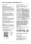
72-8795
PROGRAMMABLE DC
POWER SUPPLY
User's Manual
405 S. Pioneer Blvd
Springboro, OH 45066
mcmelectronics.com
72-8795
Programmable DC Power Supply Series
PROGRAMMABLE DC
POWER SUPPLY
Thanks for using our products. Please read this
manual thoroughly before operation.
GENERAL MAINTENANCE
CONTENTS
[Step 3]
CONTENTS
Safety Symbols
3
Product Introduction
Product Overview
Additional Features
4
4
4
Specifications of Product
5
Precautions before operation
Unpacking
Checking the Voltage
Operating Environment
6
6
6
7
Panel Introduction
Layout of the Front Panel
Layout of the Rear Panel
Function Description
7~9
7
8
8~9
Operating Instructions
Output Voltage Setting
Output Current Setting
OCP Setting
Voltage / Current Step Setting
Data Storing and Recalling Setting
Automatic Sequence Mode
Series and Parallel Operation
Communication Settings
10~12
Maintenance
Fuse Replacement
Adjustment and Calibration
Cleaning
13~15
13
14
10
10
11
11
11
11
After zeroing the voltage of the three channels, which are also saved, move
the cursor to [CURRENT] of [CH1]. Connect the ammeter and adjust the knob
to make the current reading equal 0MA. Then press [ENTER] to store the calibration
data of the corresponding channel. Move the cursor down to zero and calibrate the
current of channel 2 and channel 3 with the same procedure.
H
ZERO CALIBRATION
CH1Votage
Current
CH2Votage
Current
CH3Votage
Current
[Step 4]
After completing step 3, move the cursor to the left; press key 2(cursor down) until
the calibration interface reads “Output Calibration”. Move the cursor to a
corresponding channel and adjust the output voltage by using the rotary knob to
equal 32V reading on the voltmeter. Press [ENTER] and then the calibration data
of the corresponding channel is stored. Move the cursor down into the calibration of
the other channels with the same procedure, with channels 1 and 2 at 32 V, and
channel 3 at 6 V.
H
OUTPUT CALIBRATION
CH1Votage
Current
CH2Votage
Current
CH3Votage
Current
[Step 5]
After completing the maximum voltage calibration, connect the ammeter and adjust
the current of channel 1 to equal 3A. Press [ENTER] to save the current of the
channel. Then move the cursor to carry on with the current calibration and storage of
channel 2 and channel 3.
12
12
15
H
OUTPUT CALIBRATION
CH1Votage
Current
CH2Votage
Current
CH3Votage
Current
3. Cleaning
When the unit is unplugged, use a damp cloth or mild cleanser to wipe the housing.
Never use an abrasive cloth or harsh solvents, as these will damage the housing of
the instrument.
2
15
GENERAL MAINTENANCE
SAFETY SYMBOLS
2. Adjustment And Calibration
2.1.1 Preparation
a. Power unit on and allow 30 minutes to warm up before calibration.
Safety Symbols
b. Ambient temperature: 23±5°C, Humidity: Less than RH80%.
WARNING: Warning statements identify conditions or practices to avoid
electric shock that could cause personal injury or death.
c. Select a reliable six-and-a-half digital voltmeter with a current test
range more than 5A.
2.1.2 Output Calibration Steps:
[Step 1]
Press [SHIFT][4] to display Password input window, input Password
(293856) by using the number keys, and the Calibration window will
appear. If an incorrect password is entered, the unit returns to the
home screen.
!
CAUTION: Caution statements identify conditions or practices that
could result in damage to this product or other property.
Ground; Ground terminal
Frame or chassis ground terminal
Password
******
[Step 2]
Control the cursor by using the arrows assigned to the 8, 2, 4, 6 keys.
Set the cursor to the calibrated item of the corresponding channel, and
using a connected voltmeter for correct readings, use the rotary knob
to adjust parameters and regulate the voltage of the corresponding
channel to a 0V reading on the voltmeter. Press [ENTER] to store the
calibration data of the corresponding channel. Move the cursor down
to calibrate the other channels with the same procedure.
Tip: Use the F/C feature to switch between broad and precise incremental
control.
Zero Correct
CH1Votage
CH2Votage
CH3Votage
14
H
Current
Current
Current
!
Safety Precautions
1. Pressure, shock, abuse, and vibration should be avoided.
2. Do not dismantle, alter, or repair this unit yourself. This could easily damage
the unit, and could cause further property damage, injury, or electrical shock.
3. This unit was designed to be used with 110 volt power. Note the maximum power
and amperage settings, and fuse specifications for use with this product.
4. This unit uses three linear power supplies, and has been designed to ensure that the
machine casing and power are properly grounded when used with a grounded outlet.
5. Never use around high moisture areas, never submerge in water, and never use
with wet hands.
6. Range of operating temperature is 0°C~40°C (32°F ~ 104°F); do not use in
high temperature, high humidity, high radiation, and areas with magnetic interference.
3
PRODUCT INTRODUCTION
GENERAL MAINTENANCE
Product Overview
CH1
OFF
72-8795 Programmable Power Supply is controlled by a Micro Processor
Unit (MPU) that is designed for a communication interface by RS-232 or USB to
computer to enable advanced testing and power delivery by programmable control.
The volt age and current are contr olled by a 12 bit D/A Conver ter
with high resolution and accuracy. Also, the digital inter face provides
a speedy, precise and convenient input of information controlled by intuitive controls.
The adjustment of voltage/current is made by software calibration, eliminating
potential manual fault, that increases the precision of the instrument.
Over Voltage Protection (OVP) and Over Current Protection (OCP) can be set with the
software and utilized by the hardware to achieve precise, instant protection
to prevent damage and increase the users’ safety.
We warrant this unit to be free from manufacturer material and workmanship defects
for one year from the original date of purchase within North America. If the unit fails
during normal use withing the warranty period, please contact the authorized reseller
of this product for repair or replacement. This warranty does not apply to defects
and failure resulting from customer actions, such as mishandling, misapplication,
overloading power or current, unauthorized repair, or any modification. The reseller
and manufacturer hold the right to deny any warranty claims based on these reasons,
or to fulfill warranty with a similar product at a similar value.
Additional Features
Programmable power supply with a digital interface
Three separately adjustable linear outputs
● The 192×64 LCD Display can display multiple settings and measurements simultaneously
● Windows-based interface for user-friendly operation
● High stability and low drift
● Over Voltage, Current, and Temperature protection
● Intelligent fan control adjusts with output power
● Built-in warning buzzer
● Accurate user calibration software
● Space-saving design
● Fine adjustment knob
● 90 setting memory
● Parallel, series, and independent operation modes
● 1-second timing resolution.
●
●
CH2
OFF
CH3
OFF
CH1
OFF
CH2
OFF
CH3
OFF
3 2 . 0 0OUTV SET3 . 0 0 0 A
32. 00V 3. 000A
06. 00V 3. 000A
Shift
3 2 . 0 0OUTV SET3 . 0 0 0 A
32. 00V 3. 000A
06. 00V 3. 000A
Shift
INDEP
PARA
SERIES
INDEP
PARA
SERIES
OUT
OUT
OUT
OUT
OUT
OUT
Parallel Output Mode
OCP
OFF
OCP
OFF
SERI
Serial Output Mode
OCP
OFF
OCP
OFF
8. Communication Setting
Press [SHIFT][COMM] to access the interface for the communication setting.
Use the key directions to move the cursor to the corresponding value place. You
can set the power address, communication speed and data bit by using the rotary
knob to change the values. Press [ENTER] to store and exit.
CH1
OFF
CH2
OFF
CH3
OFF
3 2 . 0INTERFACE
0V 2. 000A
ADDR:
3 2 . 0BAUD:
0 V 19200
2 .0010 0 0 A
DATA:
9
04. 10V 2. 000A
Shift
INDEP
OCP
OFF
OCP
OFF
General Maintenance
To avoid electrical shock, do no perform any service or repair other than those outlined in these
operating instructions. Any additional attempts at servicing or modifying this unit voids all
manufacturer warranty and liability.
1. Fuse Replacement
If the fuse blows, the display will not light and the power supply will not operate.
Replace the fuse with a compatible rated fuse. The unit was originally supplied with a 5 Amp
250V glass type fuse. The fuse compartment is located at the AC plug terminal
WARNING: Replace fuse only with 250V fuse of the specific type and
rating, and always disconnect power cord before replacing fuse.
13
4
PARA
OPERATION
TECHNICAL SPECIFICATIONS
Technical specifications
5.2 Sequence range activation
After setting all needed values and delays, move the cursor over the delay value
of the last step in the sequence to be used and press [AUTO], and a box
should appear after the value. After the automatic sequence reaches this step, it
will return to the first step and continuously repeat the sequence.
Note: The following indexes are tested after unit being powered for 20 minutes.
Specifications
72-8795
Voltage
0~32V x 2,
0-6V
Current
0~3A x 3
Output
6. Automatic sequence execution
From the home screen, press [AUTO], which will set the unit to AUTO mode.
Press [OUTPUT] to activate the selected and stored settings; the unit then will
output the sequences of t voltage, current, and delay parameters. The unit will
continued to run through the sequences. Press [AUTO] to stop the automatic
sequence.
CH1
OFF
CH2
OFF
CH3
OFF
32. 00V 3. 000A
32. 00V 3. 000A
06. 00V 3. 000A
Power Effect
Resolution
Shift
AUTO
Load Effect
Programming Output Mode
OCP
OFF
OCP
OFF
Set
Accuracy
(25±5℃)
Ripple
(20Hz-20MHz)
7. Series and parallel operation mode
Press [SHIFT][ PARA/SER] to select between operation modes. Use the rotary
knob to select the desired output mode. Press [ENTER] to confirm and return to
the main screen. When the unit operates in series or parallel output modes,
channel 2 operates as the master (CH1 and CH2 will output the settings for Ch2).
In independent mode, each channel will output it’s own individual settings.
Temperature
Coefficient
(0~40℃)
Read back
Resolution
Response Time
CH1
OFF
CH2
OFF
CH3
OFF
3 2 . 0 0OUTV SET3 . 0 0 0 A
32. 00V 3. 000A
06. 00V 3. 000A
INDEP
PARA
SERIES
OUT
OUT
OUT
Readback
Temperature
Coefficient
Shift
INDEP
OCP
OFF
Independent Output Mode
Drift
OCP
OFF
Serial
synchronous
operation
12
Voltage
≤3mV(≤8mV rated current>3.0A)
Current
≤3mA(≤5mA rated current>3.0A)
Voltage
≤ 3mV(AC±5%)
Current
≤ 3mA
Voltage
10mV
Current
1mA(2mA rated current>3A)
Voltage
≤0.05 % +10 mV(+20 mV rated voltage>36V)
Current
≤0.1 % +5ma(+10 mA rated current>3.0A)
Voltage
Ripple≤1 mVrms
Current
≤3mArms(≤5mArms rated current>3.0A)
Voltage
100ppm+3mV
Current
100ppm+3mA
Voltage
10 mV
Current
1mA(2mA rated current>3.0A)
Voltage rise
10%~90%≤ 100ms
Current fall
90%~10%≤10ms(≥10% rated load)
Voltage
≤100ppm+10 mV
Current
≤150ppm+10 mA
Voltage
≤100ppm+10 mV
Current
≤150ppm+10 mA
Serial
synchronous
error
≤0.1%+20 mV
Series(Load)
20 mA
5
OPERATION
TECHNICAL SPECIFICATIONS
Set
Accuracy
Parallel
Simultaneous
Operation
Voltage≤0.05%+20 mV
Current≤0.1%+20 mV
Voltage≤5mA
Load regulation
Current≤6mA
Power
Voltage≤3 mV
regulation
Current≤6mA
Store/Recall points 0~90
Memory
Timer
Setting time
1s~9999s
Resolution
1s
Function
Auto Step running
RS232,USB interface
Interface
Physical
Specification
Dimensions
230(W)×140(H)×380(L)mm
Weights
10Kg (22 lbs)
Operation Environment
Indoor use, Altitude up to 2000 m
Precautions before operation
1.Unpacking the Instrument
The product has been fully inspected and tested at our factory before shipping.
Please carefully unpack and inspect it to check if there is any damage that may have
occurred during transportation. If any signs of damage are found, please contact our
customer service team before operation.
2. Power requirements
The product has been designed to be used with 110V 60Hz power supplies. Make
certain that the power supply and outlet are properly grounded before use. Do not
modify the power plug or cord in any way. Use only the power cable that is included
in the packaging, or a direct replacement.
6
Example: Set current at 1.500A.
Press [I SET][1][.][0][0][0][ENTER]
If the load current through output terminals exceeds the setting value, the
instrument will operate in the C.C. mode; if load current does not exceed the
setting value, the instrument will operate in the C.V. mode.
3. Over Current Protection Setting
Press[OCP] to turn on the OCP mode. OCP mode is can be turned off by
pressing [SHIFT][OCP].
4. Voltage/Current Step Setting
While using the rotary knob for changing value, pressing F/C will switch between
macro and micro incremental values to either rapidly change or fine tune values.
5. The data storage and call setting
5.1 The data storage setting
Press [SHIFT][STORE] to access the data store menu screen. Use the rotary knob
to select the channel group, and then press ENTER. Move the cursor selection
by pressing the direction key (8,2,4,6) to select voltage, current and delay time;
press ENTER, then you can input data directly. Press ENTER again to store.
CH1
OFF
CH2
OFF
CH3
OFF
3 2 . 0STORE
0 V SET
3. 000A
CH1 STORE
3 2 . CH2
0 0 VSTORE
3. 000A
CH3 STORE
06. 00V 3. 000A
Shift
INDEP
OCP
OFF
OCP
OFF
CH1 STORE
1 : 32.00 V 2.000A 0001S
2 : 43.50 V 1.253A 0002S
3 : 55.19 V 1.376A 0002S
Example: To set output voltage, current and delay time of the CH1 memory of “ 01”
to be 15.00V, 3.00A, 20S. Press [SHIFT][STORE] to access menu screen,
and us rotary knob to select Ch1 STOREl. Then press ENTER to access CH1
storage interface; move the cursor to the voltage and press ENTER to input
voltage with number keys or rotary knob, and then press ENTER to store
data. Repeat for current and delay settings. Press [SHIFT][STORE] to store
all settings.
11
OPERATION
PANEL INTRODUCTION
Operation
WARNING: To avoid electrical shock, make sure the power cord has
1.Output Voltage Setting
Select the desired channel by pressing [SHIFT][CH#] to set the cursor
to toggle that channel.
Method 1: Set output voltage by pressing [V SET] and using the number and
decimal keys to key in [voltage value], then press [ENTER].
Method 2: Press [V SET], press the rotary knob once, and turn the rotary knob
to input [voltage value]. The output voltage setting is changed
immediately during selection. Press [ENTER] to save the voltage
setting.
CH1
OFF
CH2
OFF
CH3
OFF
32. 00V 3. 000A
32. 00V 3. 000A
06. 00V 3. 000A
Shift
INDEP
OCP
OFF
OCP
OFF
CH1
OFF
CH2
OFF
CH3
OFF
V
3. 000A
32. 00V 3. 000A
06. 00V 3. 000A
been securely connected to a properly grounded outlet.
!
CAUTION: To avoid personal injury and damage, disconnect the
power cord before removing the fuse holder.
3. Operation Environment
The working ambient temperature range of this instrument is from 0° to 40°C
(32° to 104°F). Do no operate the instrument outside of this range. Extreme
temperatures can cause damage to the unit.
Shift
INDEP
OCP
OFF
OCP
OFF
Panel Introduction
Layout of Front Panel
Example: To set voltage at 18.50V.
Press [V SET][1][8][.][5][0][ENTER].
12
8 14
18 11 10 9
2. Output Current Setting:
Select the desired channel by pressing [SHIFT][CH#] to set the cursor
to toggle that channel.
Method 1: Set output current by pressing [I SET] and using number keys to key in
[current value], then press [ENTER].
Method 2: Press [I SET], press the rotary knob once, and turn the rotary knob
to input [current value]. The output current setting is changed
immediately during selection. Press [ENTER] to save the current
setting.
13
15
16
17
72-8795
PROGRAMMABLE DC POWER SUPPLY
19
21
2
22
20
23
24
25
1
CH1
OFF
CH2
OFF
CH3
OFF
32. 00V 3. 000A
32. 00V 3. 000A
06. 00V 3. 000A
Shift
INDEP
OCP
OFF
OCP
OFF
10
CH1
OFF
CH2
OFF
CH3
OFF
32. 00V
A
32. 00V 3. 000A
06. 00V 3. 000A
7
Shift
INDEP
OCP
OFF
OCP
OFF
3
4
7
6
5
FUNCTION LAYOUT
FUNCTION LAYOUT
Layout of Rear Panel
11
F/C (STEP)
12
RECALL(STORE)
13
AUTO(COMM)
Toggles automatic execute mode;
[SHIFT] [COMM] to access the interface
of the communication settings.
INDEP
Switch to independent output mode;
(PARA/SER)
[SHIFT][PARA/SER] to switch to Parallel or Serial output mode
28
14
29
Change incremental tuning value of the rotary knob;
[SHIFT][Step] to change the incremental steps
of the rotary knob
Recall the stored settings;
[SHIFT][STORE] to edit and save channel settings.
OCP
Turn OCP on or off;
(OVP RESET)
[SHIFT][RESET] key to clear over-voltage protection
15
Press first to access the second assigned function
27
SHIFT
17
CONTRAST
Toggle main unit power on/off
POWER
of a button.
26
Function description as below:
1
16
[SHIFT][CONTRAST] to access the display contrast settings,
use the rotary knob to adjust; press [ENTER] to exit setting.
[SHIFT] [
18
] to toggle the audible alert on or off.
2
DISPLAY
Displays output voltage and current, power settings,
and volume, OVP, and OCP statuses
3
CH1 OUT
CH1 output terminals
20
Move the cursor downward by pressing [ ] in the storage settings
4
CH2 OUT
CH2 output terminals
21
Move the cursor on the left by pressing [ ] in the storage settings
5
CH3 OUT
CH3 output terminals
22
6
GND Terminal
Ground terminal connecting to CASE
7
8
9
10
Rotary Knob
Press and turn to incrementally adjust power settings;
turn to cycle through menus and setting
V SET(CH1)
Set Output voltage;
[SHIFT] [CH1] to select Channel 1 settings
I SET(CH2)
OVP SET(CH3)
19
Move the cursor upward by pressing [ ] in the storage settings
Move the cursor on the right by pressing [ ] in the storage settings
23
OUTPUT
24
0~9
“.” , ENTER
25
, “0”
Set Output current:
[SHIFT] [CH2] to select Channel 2 settings
26
AC Power Socket
27
Cooling Fan
Set Over-voltage Protection value:
[SHIFT] [CH3] to select Channel 3 settings
28
8
Turn on or off output; if a channel is selected,
you can turn on or off the corresponding channel;
when you select no channel, all channels on turned on or off.
Data entry, ENTER Value output
Press [SHIFT] [
] to restore factory settings
AC power input terminal
Cooling Fan
USB communication interface
Interface
RS232C communication interface
29
9