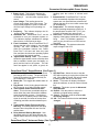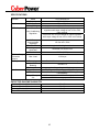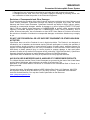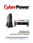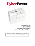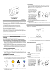
1
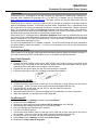
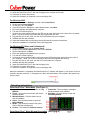
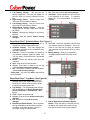
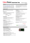
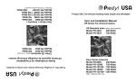
1500AVR-HO
Guaranteed Uninterruptible Power System
WHAT IS AVR?
This machine provides complete power protection open files and shutdown your computer system
from utility power that is not always consistent. during a utility power loss.
The CPS1500AVR-HO features a high level of
surge suppression (1500 Joules) for power line
surges, and provides long lasting battery backup
with dual 9AH batteries for loss of utility power and
voltage sags. The CPS1500AVR-HO ensures
consistent power to your computer system and
includes software that will automatically save your
AUTOMATIC VOLTAGE REGULATOR
The CPS1500AVR-HO controls utility power voltage levels that can be inconsistent. The incoming utility
power may be at a damaging level to important data files, but with the Automatic Voltage Regulation of
the CPS1500AVR-HO the computer will only experience a consistent voltage level. An Automatic
Voltage Regulator automatically increases low or decreases high voltage to a consistent, computer safe
110v/120v. The powerful dual 9AH batteries provide power only if the incoming voltage drops below
90v or increases above 145v.
DESCRIPTION
7 All outlets Designed for AC Adapters. Allows six
AC power adapter blocks to be plugged into the
UPS without making adjacent outlets inaccessible.
8 Coaxial Cable Surge Protection. Connect the
coaxial cable from your cable / antenna dish
source to one of the surge protector’s video
connectors market “IN”. With another section of
coaxial cable, connect the surge protector’s
corresponding video connector marked “OUT” to
the appropriate jack on your tv/vcr/other device.
9 Communication Protection Ports Communication protection ports will protect any standard
modem, fax machine or telephone.
10 Serial Port to PC
This port allows connection and communication
from the DB-9 serial port on the computer to the
UPS unit. The UPS communicates its status to
the PowerPanel Plus™ software. This interface is
also compatible with the UPS service provided by
Windows 95, Windows 98, Windows Me, Windows
NT, Windows 2000, Windows XP and Mac OS X.
11 Full-time Surge Protection Outlets All outlets
on the unit provide surge suppression for connected equipment.
12 Re-settable Circuit Breaker
The circuit
breaker provides circuit overload and fault protection.
13 Battery Power Supplied Outlets Provides
three batter-supplied outlets for connected equipment and insures temporary uninterrupted operation of your equipment during a power failure.
1 Power on Indicator This LED is illuminated
when the utility condition is normal and the UPS
outlets are providing “clean power”, free of surges
and spikes
2 Electrical Wiring Fault Indicator This LED
indicator will illuminate to warn the user that a
wiring problem exits with the AC outlet, such as
bad ground, miss ground or reversed wiring. If
this is illuminated, the user is advised to disconnect all electrical equipment from the outlet and
have an electrician check the outlet to insure
proper wiring.
3 AVR Indicator This LED indicates that the UPS
is operating in automatic voltage regulation mode.
4 Using Battery This illuminates during utility
failure, indicating that the battery is supplying
power to the battery-power supplied outlets.
5 Check Battery This illuminates indicating a
weak battery. If the indicator is still illuminated
after allowing the unit to charge for 12 hours,
replace the battery according to the instructions in
the Replacing the Battery section of this manual.
6 Power Switch can be used as a master on/off
switch for equipment connected to the battery
power supplied outlets.
INSPECTION The box should contain the following:(1) PowerPanel Plus™ software (floppy disk);
(1) serial interface cable (DB-9); (1) serial to USB cable (1) telephone communication cable; (1) user’s
manual; (1) warranty registration card; (1) UPS unit.
1
HOW TO DETERMINE THE POWER REQUIREMENTS OF YOUR EQUIPMENT
1. Make sure that the total Volt-Amp (VA) re- 3. If the power requirements of your equipment
are listed in units other than Volt-Amps (VA),
quirements of your computer, monitor and peconvert Watts (W) or Amps (A) into VA by doripheral equipment does not exceed 1500VA.
ing the calculations below. Note: The below
2. Insure that the equipment plugged into the
equation only calculates the maximum amount
three battery power-supplied outlets does not
of VA that the equipment can use, not what is
exceed the UPS unit’s rated capacity
typically used by the equipment at any one
(1500VA/900W for CPS1500AVR-HO).
If
time. Users should expect usage requirerated unit capacities are exceeded, an overments to be approximately 60% of below
load condition may occur and cause the UPS
value.
unit to shut down or the circuit breaker to trip.
TO ESTIMATE POWER REQUIREMENTS:
Watts (W) x 1.67 =
VA or
Amps (A) x 120 =
VA
Add the totals up for all pieces of equipment and multiply this total by .6 to calculate actual requirements.
There are many factors that can affect the amount of power that your computer system will require. The
total load that you will be placing on the battery-powered outlets should not exceed 80% of the unit’s
capacity.
HARDWARE INSTALLATION GUIDE
1. Your new UPS may be used immediately upon receipt.
However, recharging the battery for at least four
hours is recommended to insure that the battery’s maximum charge capacity is achieved. Charge
loss may occur during shipping and storage. To recharge the battery, simply leave the unit plugged
into an AC outlet. The unit will charge in both the on as well as the off position.
2. If you wish to use the software, connect the enclosed serial interface cable to the serial port on the
UPS and an open serial port on the computer. If you are
not going to use the software, you do not need to connect the cable.
3. With the UPS unit off and unplugged, connect your computer, monitor, and
any externally powered data storage device (Zip drive, Jazz drive, Tape
drive, etc…) into the battery power supplied outlets. Plug your peripheral equipment (printer, scanner, speakers) into the full-time surge protection outlets. DO NOT plug a laser printer, copier, space
heater, vacuum or other large electrical device into the UPS. The power demands of these devices
will overload and possibly damage the unit.
4. To protect a fax, telephone or modem line, connect a telephone cable from the wall jack outlet to the
in jack of the UPS. Connect a telephone cable the out-jack on the UPS with the CPU icon to the
modem port of the computer. The out-jack with the telephone icon can be used to protect a telephone or fax machine line.
5. Plug the UPS into a 2 pole, 3 wire grounding receptacle (wall outlet). Make sure the wall branch
outlet is protected by a fuse or circuit breaker and does not service equipment with large electrical
demands (e.g. refrigerator, copier, etc…). Avoid using extension cords. If used, the extension cord
must be rated for 15 amps.
6. Depress the power switch to turn the unit on. The power on indicator light will illuminate.
7. If an overload is detected, an audible alarm will sound and the unit will emit one long beep. To
correct this, turn the UPS off and unplug at least one piece of equipment from the battery power
supplied outlets. Wait 10 seconds. Make sure the circuit breaker is depressed and then turn the
UPS on.
8. Your UPS is equipped with an auto-charge feature. When the UPS is plugged into an AC outlet, the
battery will automatically recharge.
9. To maintain optimal battery charge, leave the UPS plugged into an AC outlet at all times.
10. To store your UPS for an extended period, cover it and store with the battery fully charged. Recharge the battery every three months to insure battery life.
POWERPANEL PLUS™ SOFTWARE INSTALLATION GUIDE
2
1500AVR-HO
Guaranteed Uninterruptible Power System
Overview
PowerPanel Plus™ is designed for use with Windows 95, Windows 98, Windows Me, Windows NT,
Windows 2000, Windows XP and Mac OS X. For Mac OS X software can be downloaded from
www.cyberpowersystems.com/downloads.htm. The latest versions can be also downloaded from the
website.
PowerPanel Plus™ works in conjunction with the UPS to provide full protection of valuable computer
systems, applications and data. In the event of a power failure, PowerPanel Plus™ automatically saves
and closes open files under auto-assigned file names or existing files names after software controlled
delay. The computer and UPS are automatically shutdown to conserve battery power. Files with autoassigned names will be saved under C:\PCTemp, where C is the name of your main hard drive. Files
that have previously been saved will be saved in their original location.
PowerPanel Plus™ is equipped with a Scheduled Shutdown feature that can automatically save and
close open files and then shutdown the computer and UPS at a user specified date and time as well as
start the computer at a user specified date and time. Use of this feature is optional and is not required
for the power failure shutdown to occur.
The use of the PowerPanel Plus™ software is optional. The UPS unit will provide full surge suppression
and battery backup without the software. You must use the software if you wish to have the automatic
shutdown feature.
Installation Guide
(Cyber Power UPS can provide surge suppression and battery backup without the software. However, if
you need to schedule for UPS Auto-shutdown, then it is necessary to install the software.)
Data Cable (Optional)
1. Turn off your UPS
2. Connect the serial interface cable to your UPS and the open serial port on the rear panel of the
computer. If you would like to use USB interface, please connect the USB adapter with the Serial
Cable then connect the USB to your computer. (See the figure)
3. Plug the UPS into an AC outlet, turn the UPS on and start your computer.
4. . Follow the instructions on the User’s Manual to complete the installation.
For Windows 95 /98 /ME
1. Turn the UPS off and unplug it.
2. Connect the serial interface cable to serial port on the UPS and an open serial port on the back of
the computer. (Note: You must use the serial cable that was supplied with the unit).
3. Plug the UPS into an AC outlet, turn the UPS on, and then start your computer.
4. Windows will find new hardware.
5. Insert the PowerPanel Plus™ disk into the floppy drive, then follow the on-screen instructions.
6. When the installation is completed, remove the floppy disk.
For Windows NT
1.
2.
3.
4.
5.
6.
7.
Click on Start, point to Settings, and then click Control Panel.
Double-click on the UPS Icon.
Remove the check mark from the box labeled UPS is installed on, and Click OK.
Acknowledge the message that the UPS is in an unknown state.
Exit to the desktop, then shutdown your computer.
Turn the UPS off and unplug it.
Connect the serial interface cable to serial port on the UPS and an open serial port on the back of
the computer. (Note: You must use the serial cable that was supplied with the unit).
8. . Plug the UPS into an AC outlet, turn the UPS on and then start your computer.
9. . Click on Start, point to Settings, and then click Control Panel.
10. Double-click on Add / Remove Programs.
3
11. Insert the PowerPanel Plus™ disk into the floppy drive, and then click Install.
12. Follow the on-screen instructions.
13. When the installation is completed, remove the floppy disk.
For Windows 2000
1.
2.
3.
4.
5.
6.
7.
Click on Start, point to Settings, and then click Control Panel.
Double-click on Power Options.
On the UPS Tab, click Select.
In the UPS Selection Dialog Box, under Manufacturers, click None.
Exit to the desktop and shutdown the computer.
Turn the UPS off and unplug it.
Connect the serial interface cable to the UPS and an open serial port on the back of the computer.
(Note: You must use the serial cable that was supplied with the unit).
8. Plug the UPS into an AC outlet, turn the UPS on and then start your computer.
9. Windows will find new hardware.
10. Insert the software disk into the floppy drive and follow the on-screen instructions.
11. When the installation is completed, remove the floppy disk.
For Windows XP (Home and Professional)
1. Click on Start and then click on Control Panel.
2.
3.
4.
5.
6.
Double-click on Power Options then click on the UPS tab.
Set the manufacturer to None.
Exit to the desktop and shutdown your computer.
Turn the UPS off and unplug it.
Connect the serial interface cable to serial port on the UPS and an open serial port on the back of
the computer. (Note: You must use the serial cable that was supplied with the unit).
7. Plug the UPS into an AC outlet, turn the UPS on and start your computer.
8. Windows will find new hardware.
9. Insert the PowerPanel Plus™ disk into the floppy drive.
10. Follow the on-screen instructions.
11. When the installation is completed, remove the floppy disk.
When the installation is completed, the PowerPanel Plus™ software will appear on your screen for a few
seconds, and then minimize. It will appear as a blue and white battery icon located in the system tray,
near the clock.
Operating Instructions
PowerPanel Plus™ Main Menu (See Figure 1 )
1. Log: Click on the log button to open the Log
Window.
2. Power: Click on the power button will exit the
software window.
3. Minimize Button: Click this button to minimize the software.
4. Setup: Click the setup button to open the
Setup Window.
5. Model: This shows the model of the CyberPower UPS that is being used.
6. Version: This shows the hardware version.
7. Status Bar: The area display messages
about the status of the software.
8. Schedule: Click this button to open the
Schedule Window.
PowerPanel Plus™ Main Window Description (See Figure 2 )
4
1500AVR-HO
Guaranteed Uninterruptible Power System
pending upon the number of minutes available.
7. Scheduled Off: PowerPanel Plus™ can be
set to automatically shutdown the computer
system at a user specified time scheduled off
settings that are set to occur within seven days
will be displayed.
8. Temperature: This indicator displays the
internal operating temperature of the unit. If
the temperature exceeds 158°F (70°C), the
indicator will change from green to red.
9. Load Level: This indicator shows the % of
capacity of the battery outlets that is currently
being
used. This indicator appears in
green or gray, but will turn red if the load exceed 90%.
10. Output Voltage: This indicator shows the
output voltage of the UPS.
1. Battery Level: This indicator displays the
current charge on the battery. The indicator
will display a
red color when a power failure
occurs.
2. Input Voltage: This reading shows the
current input voltage of the utility power. The
input normally appears in green, but will turn
red if the input voltage is not operating normally.
3. Frequency: This indicator displays the frequency of the utility power.
4.. Scheduled On: PowerPanel Plus™ can be
scheduled to turn your computer system on.
This indicator displays scheduled on settings
that will occur in the next seven days.
5. Final Countdown: When PowerPanel Plus™
detects that the utility voltage is not operating
normally, the final countdown will begin.
When the countdown reaches zero, PowerPanel Plus™ will save and close any open
files, and then shut down the operating system
in an intelligent and orderly manner.
6. Approximate Backup Time: This indicator
shows the approximate amount of backup time
that is available, based upon the battery capacity and the load on the system. This indicator can appear in red, yellow, or green, de-
PowerPanel Plus™ Setup Window (See Figure 3 )
7. UPS Self-Test: Allows the user to test the
UPS without having to unplug the unit from the
wall. When Run is clicked, the unit will switch
to battery power and the unit will beep.
8. About: This button will display information
about the software, as well as contact information.
9. Advance: This button opens the Advanced
Setup Window.
10. Default: Click this button to return the
software to original factory settings.
11. Cancel: This button exits the window without saving changes.
12. OK: This button exits the window and saves
changes.
1. UPS is Installed On: This shows the current
port that the UPS is using. The port assigned
to the UPS needs to be used exclusively for
the PowerPanel™ software.
2. Buzzer On: This toggles the audible alarm on
and off..
3. Play Sound: Voice is being played when the
UPS is turning on or facing a power outage.
4. Time between Power Failure and Shutdown: This is the user controllable delay between when the power fails and the software
starts the shutdown process. If unchecked,
the unit will run on battery until the low battery
signal is received (2 minutes of backup time
remaining) and then start the shutdown process.
5. Time between Power Failure and Initial
Warning: This setting determines the delay
between when the power fails and the first
audible alarm.
6. Delay between Warning Messages: User
adjustable setting for the delay between the
audible alarms that occur during a power failure.
PowerPanel Plus™ Advanced Setup (See Figure 4 )
5
7. OK: Exits the windows and saves changes.
8. Cold Start: When enabled, the UPS can start
in the absence of AC power. To maximize
battery life, it is recommended to keep this
disabled.
1. Low Battery Voltage: This sets the low
battery cut-off level. The user can slightly extend the UPS run time by adjusting this setting.
2. High-Voltage Failure: Sets the upper level
where the UPS will switch to battery.
3. Low-Voltage Failure: Sets the lower level
where the UPS will switch to battery.
4. Battery-Mode Output Voltage: Sets the
voltage that the unit will output when running
on battery.
5. Default: Restores the settings to the factory
defaults.
6. Cancel: Exits the window without saving
changes.
PowerPanel Plus™ Schedule Menu (See Figure 5 )
8. Turn Off: Select the day/date and time that
you want the system to shutdown. This is optional to use and has no effect on whether
your computer will shut down during a power
failure.
9. Weekly Setting: Allow you to schedule a
shutdown/startup based on the day of the
week.
1. Special Setting: This setting allows you to
schedule a one-time startup/shutdown.
2. Schedule Display: This area displays the
days/dates and times of any scheduled startups and shutdowns.
3. Turn On: Select the day/date and time that
you want the computer system to restart. Can
only be used in conjunction with a scheduled
shutdown.
4. Delete: Delete the selected item from the
schedule.
5. Add: Adds an item to the schedule.
6. Cancel: This button is used to exit the log
window without saving any changes.
7. OK: This button is used to exit the shutdown
window and save any changes.
Please note: You must click Add to add the item
to the schedule.
PowerPanel Plus™ Log Menu (See Figure 6 )
1. Event Option Button: When this option is
selected, the log will display different PowerPanel Plus™ events, such as power failure,
program start, and program end.
2. Log Display: This area displays the information as selected by the Event, Closed Application Information, or Data Record option
button.
3. Clear: Clears the selected log.
4. Cancel: Exits the screen without saving any
changes.
5. OK: Exits the screen and saves any
changes.
6. Data Record Option Button: When selected,
the log will display a record of the items that
are shown in the main window, such as input/output voltage and temperature.
7. .Closed Application Information Option
Button: When this option is selected, the log
will display the names and locations of any
files that were auto-saved by the software
6
1500AVR-HO
Guaranteed Uninterruptible Power System
TESTING YOUR UPS SYSTEM
Once you have set up your UPS system, you may wish to test it. Make sure that the UPS has been
charged for at least 4 hours before performing this test.
If you are using PowerPanel Plus™:
1. With your UPS and computer on, open an application such as notepad.
2. Enter some data into the application.
3. Unplug the UPS from the AC outlet.
When a power failure occurs, PowerPanel Plus™ will appear on the screen. The outlet and battery
symbols will change to indicate a power failure. The countdown timer will move towards zero. When
the timer reaches zero, the software will begin to save and close any open applications. The software
will auto-assign names to any files that have not been previously saved, and then save the file to the
PCTemp folder which is located in the root directory of your C drive (where C is the name of your main
hard drive). Once all open files have been saved and closed, PowerPanel Plus™ will shut down the
operating system. Once the operating system is shutdown, the UPS will turn off within 90 seconds.
Wait until the UPS has turned off before plugging the UPS back into the outlet.
Once the test has been completed, plug the UPS back into the AC outlet and turn it back on. You may
then restart your computer. Please allow 4 hours for the UPS to recharge before attempting another
self-test.
If you are not using PowerPanel Plus™:
1. Have your computer and UPS turned on.
2. Unplug the UPS from the wall to simulate a power failure.
3. The UPS will begin beeping, indicating a power failure.
4. Save and close any open files.
5. Shut down the operating system.
6. Once the computer system is shutdown, turn the UPS off.
As the battery discharges, the unit will beep more rapidly, indicating that the battery is
nearing discharge. Once the test is complete, plug the UPS back in to the AC outlet and
start your computer. Please allow 4 hours for the UPS to recharge before attempting another self-test.
REPLACING THE BATTERY
CAUTION! Read and follow the IMPORTANT SAFETY INSTRUCTIONS before servicing the battery.
Service the battery under the supervision of personnel knowledgeable of batteries and their
precautions.
CAUTION! Use only the specified type of battery. See your dealer for replacement batteries.
CAUTION! The battery may present risk of electrical shock. Do not dispose of battery in a fire, as it
may explode. Follow all local ordinances regarding proper disposal of batteries.
CAUTION! Do not open or mutilate the batteries. Released electrolyte is harmful to skin and eyes and
may be toxic.
CAUTION! A battery can present a high risk of short circuit current and electrical shock. Take the
following precautions before replacing the battery:
1.Remove all watches, rings or other metal objects.
2.Only use tools with insulated handles.
3.Do not lay tools or metal parts on top of battery or any terminals.
4.Wear rubber gloves and boots.
5.Determine if the battery is inadvertently grounded. If inadvertently grounded, remove source of
ground. CONTACT WITH GROUNDED BATTERY CAN RESULT IN ELECTRICAL SHOCK!
The likelihood of such shock will be reduced if such grounds are removed during installation and
maintenance (applicable to a UPS and a remote battery supply not having a grounded circuit).
7
TO REPLACE THE BATTERYS
1.
2.
3.
4.
5.
6.
7.
8.
Turn off and unplug all connected equipment.
Turn the UPS off and unplug it from the AC power source.
Turn the UPS upside down.
Remove the 6 retaining screws.
Turn the UPS right side up and remove the outlet cover.
Remove the batterys from the compartment.
Disconnect the battery wires from the batterys.
Install the replacement battery by connecting the red wire to the positive (+) terminal of the
battery and connecting the black wire to the negative (-) terminal of the battery.
9. Slide the battery back into the compartment.
10. Replace the outlet cover and the 6 retaining screws.
11. Recharge the unit for 4 – 8 hours to ensure the UPS performs expected runtime.
REMINDER: Batteries are consider HAZARDOUS WASTE and must be disposed of properly. Contact
your local government for more information about proper disposal and recycling of batteries.
TROUBLE SHOOTING
Problem
Full-time surge
protection
outlets stop
providing
power to
equipment.
The UPS does
not perform
expected
runtime.
Possible Cause
Circuit breaker has tripped
due to an overload.
Solution
Turn the UPS off and unplug at least one piece
of equipment. Wait 10 seconds, reset the circuit
breaker by depressing the button, and then turn
the UPS on.
Battery not fully charged.
Recharge the battery by leaving the UPS
plugged in.
Contact CyberPower Systems about replacement batteries at
[email protected]
The UPS will
not turn on.
The on/off switch is designed
to prevent damage by rapidly
turning it off and on.
The unit is not connected to
an AC outlet.
The battery is worn out.
Turn the UPS off. Wait 10 seconds and then
turn the UPS on.
Mechanical problem.
Contact CyberPower Systems about at
[email protected]
The serial cable is not
connected.
Connect the serial cable to the UPS unit and an
open serial port on the back of the computer.
You must use the cable that came with the unit.
The serial cable is connected
to the wrong port.
Check the back of the computer for an additional
serial port. Move the cable to this port.
The unit is not providing
battery power.
Shutdown your computer and turn the UPS off.
Wait 10 seconds and turn the UPS back on.
This should reset the unit.
You must use the cable that was included with
the unit for the software and the unit to be able
to communicate.
PowerPanel™
Plus is inactive
(all icons are
gray).
Battery is slightly worn out.
The unit must be connected to a 110/120v 60Hz
outlet.
Contact CyberPower Systems about replacement batteries at
[email protected]
The serial cable is not the
cable that was provided with
the unit.
8
1500AVR-HO
Guaranteed Uninterruptible Power System
DEFINITIONS FOR ILLUMINATED LED INDICATORS
Power
On
On
Wiring
Fault
AVR
Off
Off
Using Check Circuit Alarm
Battery Battery Breaker
Off
Off
Set
Condition
Off
Normal
On
Off
Flash
Off
Off
Set
Off
AVR- AVR is maintaining a consistent 120v level
(±5%) during a power sag.
ON
Off
On
Off
Off
Set
Off
AVR- AVR is maintaining a consistent 120v
(±5%) during a power surge
Off
On/Off
Off
On
Off
Set
Two
Beeps
Utility Failure- The UPS is providing battery
power to the Battery-Power Supplied outlets.
Off
On/Off
Off
On
Off
Set
Rapid
Beeps
Utility Failure- The UPS is providing battery
power. The rapid beeps indicate the battery will
run out of charge within a few minutes.
Off
Up
Two
beeps or
rapid
beeps
Off
Set
Long
Beep
Off
Off
Off
On
On/Off
On/Off
Off
Off
Off
On
Off
Up
Long
Beep
On
On/Off
On/Flas
h/Off
Off
On
Set
None
On/Flas
On/Off
h/Off
Off
Off
Off
Off
Off
Set
Off
On/Off
On/Off
On/Flas
h/Off
Flash
Flash
Set/Up
Off
On/Off
On/Off
On/Off
On
On/Flas
h/Off
Flash
On/Flas
On/Off
h/Off
Flash
Set/Up
On/Off Set/Up
Three
Beeps
None
9
Overload- Occurs in the Full-time Surge Protection Outlets. Turn the UPS off and unplug at
least one piece of equipment from the UPS. Wait
5 seconds, reset the circuit breaker and turn the
UPS on.
Overload- Occurs in the Battery-power Supplied Outlets. Turn the UPS off and unplug at
least one piece of equipment from the UPS. Wait
5 seconds, reset the circuit breaker and turn the
UPS on.
Overload- Occurs in the Battery-power Supplied Outlets. Turn the UPS off and unplug at
least one piece of equipment from the UPS. Wait
5 seconds, reset the circuit breaker and turn the
UPS on.
Weak Battery- Recharge the battery for at least
8 hours. If Check Battery is illuminated contact
CyberPower Systems for battery replacement
information.
Surge Protection Malfunction- Lightning induced power line surge has damaged the surgeprotect function. Please contact CyberPower
Systems
Scheduled Turn-on- If the two battery indicators
are flashing in rotation, the UPS is waiting to turn
on as configured in the schedule.
Cold Start Disabled- If the two battery indicators
are flashing at the same time, the cold-start has
been disabled. The UPS will not start in the
absence of AC power.
Electrical Wiring Fault- This indicates a wiring a
problem such as a bad ground, missed ground or
reversed wiring within the AC outlet. User is
advised to disconnect all electrical equipment
from the outlet and have the outlet checked by an
electrician.
SPECIFICATIONS
General
Input
Model
Capacity
Frequency
Voltage Range
UPS-Output
Line Conditioning
Regulation
Full-time Surge
Protection
Output
Battery
Interface
CPS1500AVR-HO
1500VA (900W)
57Hz to 63Hz
90v – 145v
AVR Max. boost 12% of input voltage for output
regulation while input voltage is from 10% to 30%
under nominal.
AVR buck 12% of input voltage for output regulation
while input voltage is from 10% to 26% over nominal
On Battery
Output voltage
regulation
Transfer Time
On battery output
wave form
Max. load
4ms typical, including detection time
Max. Load
12.0 Amps
Battery type
Number of
Batteries
Recharge Time
Communication
Sealed, Maintenance-free lead acid battery
LED Indicators
Output Receptacles
120 Vac ±5%, 60Hz
Simulated Sine Wave Form
1500VA (900W)
12V/9AH x 2
4 to 8 hours from total discharge
RS-232 and USB with Plug and Play interface.
Power On, Electrical Wiring Fault, AVR, Using Battery,
Check Battery
3 Battery-powered and full-time surge protection
6 full-time surge protection
EXPECTED RUNTIME IN MINUTES
Desktop PC with 15” Monitor
Desktop PC with 17” Monitor
Desktop PC with 21” Monitor
Tower PC with 21” Monitor
72 - 100
56 - 80
45 – 65
40 - 60
10
1500AVR-HO
Guaranteed Uninterruptible Power System
Limited Warranty and Power Control Guarantee
In purchasing CPS1500AVR-HO in the United States or Canada, the original end user receives a
Limited Warranty and CyberPower's Power Control Guarantee from Cyber Power Systems (USA), Inc.
(for ease of reading, referred to as "CyberPower"). The Limited Warranty and the Power Control Guarantee are intended to be the original end-user's exclusive rights and remedies. The Limited Warranty
and the Power Control Guarantee are separate, all though they are related.
Limited Warranty. The original end user (referred to as the "Initial Customer") receives an express
limited warranty (referred to as the "Limited Warranty") for the CPS1500AVR-HO purchased from
CyberPower (referred to as the "Product"). The Limited Warranty is for the Product itself. The terms of
the Limited Warranty are explained below.
Power Control Guarantee. CyberPower also provides the Initial Customer with protection in the event
that the Product is not free from defects in materials and workmanship, and certain equipment connected to the Product is damaged (the "Power Control Guarantee"). The Power Control Guarantee
protects the Initial Customer for damage to equipment plugged into the Product. The terms of the Power
Control Guarantee are explained below.
The Limited Warranty and the Power Control Guarantee are subject to the terms set forth below. Additionally, State or Provincial law may adjust the terms of the Limited Warranty or the Power Control
Guarantee or the State or Province may impose additional obligations, or additional "implied warranties."
To the extent necessary to comply with those laws, the terms of the Limited Warranty and the Power
Control Guarantee should be read to adjust to those requirements only to the extent necessary to
comply with such local law.
If you are an Initial Customer, you are asked to read the following terms and conditions carefully before
using the Product. By using the Product you consent to be bound by and become a party to the Limited
Warranty and Power Control Guarantee. If you do not agree to the terms and conditions of the Limited
Warranty and Power Control Guarantee, you should return the Product for a full refund prior to using it.
REGISTRATION
CyberPower requests that you complete and return the Warranty Registration Card enclosed with the
Product or register the Product at its website (www.cyberpowersystems.com) to establish that you are
the Initial Customer of the Product, and therefore entitled coverage under the Limited Warranty and the
Power Control Guarantee. (Registration is not required for Limited Warranty coverage, but note if you do
not complete a registration card you will be required to provide proof of purchase, as described below, to
have the benefits of this Limited Warranty.)
LIMITED WARRANTY
CyberPower warrants to you, the Initial Purchaser, that the Product will be free from defects in material
and workmanship for three years from the date of original purchase, subject to the terms of this Limited
Warranty.
Any Implied Warranty of Merchantability or for Fitness for a Particular Purpose, if applicable
to the Product, is limited in duration to the period of ownership by the Initial Customer. This provision
shall NOT create any Implied Warranty or Merchantability or of Fitness for a Particular Purpose that
would not otherwise apply to the Product. NOTE: Some States do not allow limitations on how long
an implied warranty lasts, so the above limitation may not apply to you.
To be covered you must still be the owner of the Product at the time of the failure that results in the
claim made under this Limited Warranty.
11
Exclusive Remedies Under Limited Warranty.
Your exclusive remedy and CyberPower's' sole obligations are as follows for the Product:
If (a) the CyberPower Product you purchased and still own is defective in material or workmanship
under this Limited Warranty or any applicable warranty imposed by law, and
(b) all Limited Warranty requirements have been met, CyberPower will repair or replace the
Product if it proves to be defective in material or workmanship during the Warranty Period.
Making a Limited Warranty Claim.
To make a Limited Warranty claim on a Product, you must do the following:
1. Complete and return the CyberPower Warranty Registration Card, or provide reasonable proof of
purchase (for example, a sales receipt) that establishes you as the Initial Customer (the original enduser consumer purchaser) of the Product and prove that the Product was purchased within three (3)
years of the event for which you want to make a claim for warranty service.
2. Call CyberPower at (952) 403-9500 or (877) 297-6937 (toll free), write to CyberPower at 5555
12th Ave. East, Suite 110, Shakopee, MN 55379, or e-mail CyberPower at
[email protected], within ten (10) days of the event for which you want to make a
claim.
3. When you contact CyberPower, identify the Product, the Purchase Date, and request Return Materials Authorization (RMA) information from CyberPower.
4. Pack and ship the Product to CyberPower as instructed in your RMA. Show the RMA code on the
shipping label or include it with the Product. You MUST prepay all shipping costs and you are
responsible for packaging and shipment.
CyberPower will inspect and examine the Product within ten (10) days of receipt. If the Product is not as
warranted, CyberPower will repair or replace the Product and return it to you at CyberPower's expense,
or, if CyberPower is unable to or decides not to repair or replace the Product (if defective) within a
reasonable time, CyberPower will refund to you the full purchase price you paid for the Product (purchase receipt showing price paid is required).
POWER CONTROL GUARANTEE
If you are the Initial Purchaser and the Product is still covered by the Limited Warranty, the Power
Control Guarantee provides protection for damage to equipment connected to the Product ("Connected
Equipment"), subject to certain terms and limitations.
The Power Control Guarantee is not "first dollar" coverage. CyberPower's obligation is reduced by any
amounts that Initial Customer is entitled to recover from other sources regarding the Connected Equipment, including insurance, other warranty, or extended warranty coverage, whether or not the Initial
Customer makes a claim for recovery, including but not limited to a claim under any applicable insurance, other warranty, or extended warranty.
The Limited Warranty does not cover Connected Equipment, but as is explained below, to be covered
under the Power Control Guarantee, the Connected Equipment must have been damaged due to a
failure of the Product. The Connected Equipment must have been damaged due to a defect in materials
or workmanship of the Product
In the event of damage to the Connected Equipment, your exclusive remedy, and CyberPower's sole
obligations, are as follows for Connected Equipment. If (a) the Product purchased and owned by you is
defective in material or workmanship; (b) the Limited Warranty requirements have been met (except that
the three year limitation of the Limited Warranty does not limit the Power Control Guarantee, which is for
the lifetime of the Product), and; (c) none of the limitations or exclusions on warranty coverage apply (or
than the three year limit), CyberPower will (as CyberPower elects, as permitted by law), repair, replace,
12
1500AVR-HO
Guaranteed Uninterruptible Power System
or pay the Agreed Damage Amount (defined below) for, the item(s) of your electronic equipment directly
and properly connected to the product (the "Connected Equipment") if that Connected Equipment is (x)
damaged by AC power line transients, spikes, or surges on properly installed, grounded, and codecompliant 120 volt power lines in the United States and Canada, or by transients, surges or spikes on
standard telephone equipment lines, or Base 10/100T Ethernet lines that are properly installed and
connected (a "Power Disturbance") and (y) is directly plugged into and properly connected to a CyberPower Product in its original condition which is properly operated when a Power Disturbance passes
through the CyberPower Product and (y.1) exhausts the protection capacity of the CyberPower Product
or (y.2) damages the CyberPower Product. This provision sets out the only liability of any character of
CyberPower for direct, indirect, special, consequential, and/or incidental damages under our Limited
Warranty, applies only to Connected Equipment, and all such Liability is limited to the Agreed Damage
Amount.
Making a Power Control Guarantee Claim.
To make a Warranty claim for damage to Connected Equipment under the Power Control Guarantee,
you must do the following:
1. Complete and return the CyberPower Warranty card or provide reasonable proof of purchase, for
example, a sales receipt that establishes you as the original end-user consumer purchaser of the
Product.
2. Call CyberPower at (952) 403-9500 or (877) 297-6937 (toll free), write to CyberPower at 5555
12th Ave East, Suite 110, Shakopee, MN 55379, or e-mail CyberPower at
[email protected] within ten (10) days of the date of the event for which you wish to
make a claim for warranty service.
3. When you contact CyberPower, identify the Product, the Purchase Date, and the item(s) of Connected Equipment. Have information on all applicable insurance or other resources of recovery/payment that are available to the Initial Customer and the name of the power utility supplier for
the location of the Connected Equipment and Request a Return Materials Authorization (RMA).
4. Pack and ship the product to CyberPower and, if requested, the item(s) of Connected Equipment,
a repair cost estimate for the damage to the Connected Equipment, and all claim forms that CyberPower provides to you. Show the RMA number on the shipping label or include it with the product.
Initial Customer shall prepay all shipping costs, must pay the cost of the repair estimate and
is responsible for packaging and shipment.
CyberPower’s Duties.
CyberPower will inspect and examine the Product and the item(s) of Connected Equipment (or at
CyberPower's election, your written statement and repair cost estimate for those item(s)). You must
return the product for inspection.
If the damage to Connected Equipment is covered by the Power Control Guarantee, CyberPower will (in
addition to Limited Warranty remedies for the CyberPower Product itself) repair (or pay the costs of
repair) or replace the Connected Equipment or, at the option of CyberPower, as permitted by law, pay to
the Initial Customer the "Agreed Damage Amount" (up to the aggregate limits stated below) for all
item(s) of Initial Customer's Connected Equipment. The "Agreed Damage Amount" for all items of Initial
Customer's Connected Equipment shall be the lesser of the amount determined under Clause (1) or (2)
below, reduced by any amounts described in Clause (3) below:
1. The fair market value of the Connected Equipment as established by the lower of (a) the average
price the same or similar items are being sold for on E-bay, (b) the price list of Orion Blue Book on
the date of occurrence (or if such price list is no longer published, a published or announced price
list reasonably selected by CyberPower), or (c) the lowest price the same or similar items can be
purchased for in the United States; or
2. The aggregate ceiling amount for all Connected Equipment: CyberPower 1500AVR-HO $40,000.00
13
3. The amount(s) of all payment you have or are entitled to receive from insurance, other warranties,
extended warranties, or from other sources or persons for the Connected Equipment or damage to
such equipment so that CyberPower’s maximum liability shall be reduced to reflect all such other
payments or sources of recovery
If CyberPower replaces the connected equipment or pays to the Initial Customer the Agreed Damage
Amount, the Initial Customer shall transfer all item(s) to CyberPower without warranty by the Initial
Customer, but free of lien or other interest.
CONDITIONS COMMON TO THE LIMITED WARRANTY AND THE POWER CONTROL
GUARANTEE
The Limited Warranty and the Power Control Guarantee are the only and the exclusive express warranty of CyberPower with respect to the Product. This exclusion of other express warranties applies to
written and oral express warranties.
LIMITATION: THE LIMITED WARRANTY AND THE POWER CONTROL GUARANTEE
DO NOT COVER
The Limited Warranty and the Power Control Guarantee are intended to exclusive rights and remedies
and replace any other rights, to the extent allowed by law.
1. As to the CyberPower Product, the limited warranty does not cover or apply to: misuse, modification, operation or storage outside environmental limits for the Products, in transit, in shipment, or in
storage, damage or deterioration, improper operation or maintenance, or use with items or equipment not designed or intended for use with the product.
2. As to Connected Equipment, the Power Control Guarantee covers only damage within the specific terms of the Power Control Guarantee to Connected Equipment (and only up to the applicable
aggregate ceiling amount).
3. The Power Control Guarantee does not cover damage to Connected Equipment or apply if the
Product has been operated in a failure mode or not in compliance with CyberPower operating instructions and manuals, or if the Connected Equipment has been operated in a failure mode or not
in compliance with the instructions and manuals of its manufacturer/vendor.
The Limited Warranty and the Power Control Guarantee Do Not Apply Unless The
Initial Customer:
1. Has properly connected the Product and the Connected Equipment to properly wired and
grounded outlets (including compliance with electrical and safety codes of the most current electrical
code (ANS/NFPA 70), without the use of any adapters, extension cords of other connectors.
2. Has provided a suitable and proper environment for use and installation of the Product and Connected Equipment.
3. Has properly installed and operated the CyberPower Product and Connected equipment.
4. Has operated the Product at all times within the limitations on the Product’s VA capacity as stated
in this User Manual.
CyberPower Does Not Cover or Undertake Any Liability in Any Event for Any of the
Following:
1. Loss of or damage to data, records, or software or the restoration of data or records, or the reinstallation of software.
2. Damage from causes other than AC Power Line Transients, spikes, or surges on properly installed, grounded and code-compliant 120 volt power lines in the United States and Canada; transients, surges or spikes on standard telephone land lines, PBX telephone equipment lines or Base
10T Ethernet lines, when properly installed and connected. (This exclusion applies, for example, to
fluctuations in data transmission or reception, by CATV or Therefore transmission or fluctuations, or
by transients in such transmission.
14
1500AVR-HO
Guaranteed Uninterruptible Power System
3. Damage from any circumstance described as excluded above with respect to the product.
4. Damages from fire, flood, wind, rain, rising water, leakage or breakage of plumbing, abuse, misuse or alteration of either the product or the Connected Equipment.
Exclusion of Consequential and Other Damages.
The sole and exclusive remedies of the Initial Customer are those provided by the Limited Warranty and
Power Control Guarantee. CyberPower excludes any liability for personal injury under the Limited
Warranty and Power Control Guarantee. CyberPower excludes any liability for direct, indirect, special,
incidental or consequential damages, whether for damage to or loss of property [EXCEPT FOR (AND
ONLY FOR) the specific limited agreement of CYBERPOWER to provide certain warranty benefits
regarding "Connected Equipment" under the "CYBERPOWER Power Control Guarantee"], loss of
profits, business interruption, loss of information or data. NOTE: Some States or Provinces do not allow
the exclusion or limitation of incidental or consequential damages, so the above limitation may not apply
to you.
DO NOT USE FOR MEDICAL OR LIFE SUPPORT EQUIPMENT OR OTHER HIGH RISK
ACTIVITIES.
CyberPower does not sell the Products for use in high-risk activities. The Product is not designed or
intended for use in hazardous environments requiring fail-safe performance, including the operation of
nuclear facilities, aircraft navigation or communication systems, air traffic control, weapons systems, life
support or medical applications or for use in any circumstance in which the failure of the Product could
lead directly to death, personal injury, or severe physical or property damage, or that would affect
operation or safety of any medical or life support device (collectively, "High Risk Activities"). CyberPower
expressly disclaims any express or implied warranty of fitness for High Risk Activities.
CyberPower does not authorize use of any of its products use in any High Risk Activities.
ANY SUCH USE IS IMPROPER AND IS A MISUSE OF CYBERPOWER PRODUCTS.
The Limited Warranty and the Power Control Guarantee are governed by the laws of the United States
and the State of Minnesota, without reference to conflict of law principles. The
application of the United Nations Convention of Contracts for the International Sale of Goods is expressly excluded.
Contact Information: CyberPower's address is 5555 12th Ave East, Suite 110, Shakopee, MN 55379
and its phone number is (952) 403-9500 or (877) 297-6937 (toll free). CyberPower is the warrantor
under this Limited Warranty. You may also contact CyberPower on the Internet at
www.cyberpowersystems.com.
15