1
Less noise • More sound
RT-IS
Input Switcher
User Manual
V1.1
NTI Headquarters
Im alten Riet 102, 9494 Schaan
Liechtenstein / Europe
Phone: +423 – 239 6060, Fax: +423 – 239 6089
[email protected], www.nt-instruments.com
V 1.1 / June 05 / MBe
RT-IS
User Manual
1 DESCRIPTION
NTI’s RT-IS is an input switcher that comprises four (4) inputs and two (2) outputs. In normal
operation, it is used as a two-channel 2:1 matrix. Additionally, the OUT LINK connector
allows operating the RT-IS as a single-channel 4:1 matrix. For this purpose, the OUTPUT B
(or A) has to be connected externally OUT LINK A (or B).
The internal wiring of the input connectors can be controlled (switch ON/OFF) from a PC via
the USB interface. Two DIP-switches define the individual device ID of the RT-IS.
Consequently, up to four (4) RT-IS units can be controlled from one PC.
The four LEDs on the front panel indicate the active inputs.
The inputs and output connectors of the RT-IS are of type XLR female / male. Additional
GND LIFT switches allow disconnecting the audio ground (Pin 1 of XLR) of the input
connectors.
INPUT B2
GND LIFT
INPUT B1
GND LIFT
INPUT A2
GND LIFT
INPUT A1
GND LIFT
USB
The RT-IS must only be used as an input switcher, whereby the input current
must not exceed 80 mA.
USB
ADRESS
(DIP)
EXTERNAL LINK
Fig 1 RT-IS block diagram
p. 2/5
OUT LINK B
(XLR)
OUTPUT B
(XLR)
OUT LINK A
(XLR)
USB
Interface
OUTPUT A
(XLR)
NOTE
RT-IS
2
User Manual
INSTALLATION
2.1 Wiring
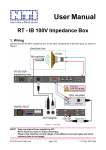
RT-IS is used in combination with a suitable PC-software from NTI (i.e. RT-Speaker, RT-ATS
or RT-Compliance). The wiring details are shown in the User Manuals of the corresponding
packages.
NOTE
Operate the RT-IS Input Switcher only under control of a NTI PC-software to
avoid damages of peripheral devices or the whole system.
2.2 USB Driver Software
Step 1
Connect the RT-IS via an USB cable to the controller PC. As soon as you do this for the first
time, the following message appears:
Select the entry “Install from a list or specific
location …” and click in “Next”.
Fig 2 Installer screen #1
Step 2
Insert the CD-ROM with the control software to your controller PC.
On the second installation panel, select the
entry “Search for the best driver in these
locations”, tick the box “Search removable
media …” and click on “Next”.
Fig 3 Installer screen #2
p. 3/5
RT-IS
User Manual
Step 3
As soon as the installer has found the USB driver on the CD-ROM, the following message
shows up:
Click on “Next” to confirm the installation.
Fig 4 Installer screen #3
Step 4
As soon as the driver has been installed
successfully, click on “Finish”.
Fig 5 Installer screen #4
2.3 Device Address Selection
The DIP-switch on the RT-IS rear panel defines the individual
address of the unit. Since the switch can be adjusted in four different
states (“0“, “1“, “2“ or “3“), it is possible to connect & control up to four
RT-IS units by one PC.
Example
The DIP-switch settings shown in Fig 6 represent the device address
“1” (= 0*2 + 1*1).
0
1
2 1
Device ID
Fig 6 DIP-Switch
p. 4/5
RT-IS
3 SPECIFICATIONS
3.1 Accessories
•
•
USB cable (included)
XLR cable (included)
3.2 Audio Inputs
Connectors:
XLR female
No. of inputs:
4 (each with a ground lift switch)
Max. input voltage:
100 Vpeak
Max. input current:
80 mA
Bandwidth:
DC to 20 kHz
3.3 Audio Outputs
Connectors:
XLR male (OUTPUT A, B)
XLR female (OUT LINK A, B)
No. of outputs:
2+2
Bandwidth:
DC to 20 kHz
3.4 USB Interface
Connector:
USB B type
USB address:
4 addresses (0–3), defined by DIP-switch setting
3.5 General
Switch ON/OFF time:
~1 ms
Temperature, humidity:
0° to 45° C (40 to 110 F)
R.H. < 90% non-condensing
Dimensions:
19” rack device, 1 rack unit high
p. 5/5
User Manual