1
SOLAR60,SOLAR80 Solar Charging and
discharging Controller
User s Manual
1:Product introduction
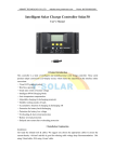
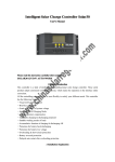
Solar LCD series a kind of intelligent, multi-purpose solar charge and discharge controller
LCD screen display
Battery reverse discharge protection
Easy operation interface
Battery reverse polarity protection
PWM charging mode
Battery under voltage protection
Parameter user can reset
Overload, short-circuit protection
A key to open and close the load
Automatic temperature compensation function
A key to restore the factory settings
Optional USB 5V charging (for 500mA)
2: Installation Instructions
Installation
1
Ready Qi installation tools and materials, and cable.
Please matching suitable cable
2
Ensure that the current density <4A/mm2 this will help to
reduce the line pressure drop.
Recommended: 30A current 10mm2 60A current
20mm2 80A current 25 mm2 cable. Check whether the
installation site
Comply with the relevant safety requirements, avoid
damp, dusty, there is easy
Inflammable, explosive and corrosive gases place to
install using the controller
3
Install the controller fixed to the vertical plane, see Section V mounting aperture and hole spacing.
In order to ensure a good controller cooling conditions, the controller on the bottom of each
reserved 10cm space
4
As shown on the right wiring sequence: load, battery, solarQ
Battery plate is connected to the controller to be taken to ensure that the load, battery,
The polarity of the solar cell panel and controller
5
Before use: external temperature sensor probe into the left of the controller temperature probe
interface probe placed in similar battery temperature. (Line extension must be built-in devices of
the external temperature probe coextensive Otherwise, the controller will control parameters of the
temperature compensation of the error
6
Warning: In order to prevent accidents from occurring, install: non-professionals can not be
engaged in loading and unloading operations
3.LCD operating interface description
1:LCD graphic symbol description
LOAD ON 1 H---23H
Load control (1 hour --- 23 hours can be set)
LOAD ON 24H
24 hour -is normally open state
0h-light control mode, power supply load after dark, closed after daybreak the load
24h-represents a normal mode, in the case of no fault, the load is always in the power supply state.
1h ~ 23h-light control delay mode, after dark began to power the load, and delay to set the time to close
the load.
Charging current
Discharge current
Voltage charging station (can be
set)
Undervoltage protection voltage
(can be set)
Temperature display (around the
probe)
2
Undervoltage recovery voltage
(can be set)
Function keys:
“+”Set
: Toggle key
parameters:
"plus"
“-”
Set
parameters:
Manual switch load
"Minus"
Long press and hold this button for 5 seconds to restore the factory settings
"×" error or system failure, click this button, you can troubleshoot or eliminate "x"
3 Parameter settings (≥ 5 seconds keystrokes, parameters are saved automatically)
:PV OFF:88.8V→LOAD ON:24H→LOAD OFF:88.8V→LOAD ON:88.8V(Set order (automatic cycle)
+
Parameters "+" setting
-
Parameters "-" setting
This button can be "manually" open load or manually close the load.
Long press and hold this button for 5 seconds to restore the factory settings
"×" error or system failure, click this button, you can troubleshoot or eliminate "x"
4
Common fault with processing methods
Battery under-voltage protection
a)
b)
c)
Battery normal power supply
Under voltage protection and handling: screen display as shown on the right indicates the
battery voltage is below the undervoltage protection voltage, the controller has entered
undervoltage
Retaining state, disconnect the load circuit. Using solar panels or charger to charge the battery
when the accumulator
After the battery voltage reaches the undervoltage recovery voltage, the controller will restore
power to the load, into normal working condition
1)
Overload protection and processing methods
methods:
The screen shown at right load circuit current is greater than the rated current or load
short-circuit, overload state controller has entered. Reduce the load troubleshooting,
press
the button, restore power to the load
or
System fault
2)
Fault has ruled out
To charging failure handling method
a)
Solar energy to battery charging, if there is no correct configuration solar panels of
power or exceed rated charging current, voltage, will appear charge fault, the
checking and debugging, press
3)
the button, recoverability work.
Charge fault
Solar panels fault and processing:
a)
Fault has ruled out
24 hours in the case of sun light, the controller is not charging, the solar energy is not
connected or not connected correctly, check the solar panel to the connecting cable of the
controller is open, troubleshooting, recoverability work.
No solar charge
5 Parameter table
model
Solar30/60/80
Parameters
Rated working
30A 60A
80A
current
Rated working
12V/24V
voltage
Solar panels voltage
≤48V
Float
charging
voltage(settable)
13.8V/27.6V
Low voltage
protection(settable)
10.7V/21.4V
Low voltage
recovery(settable)
12.5V/25.0V
No-load loss
≤25mA
Loop pressure drop
≤160mV
Charging mode
Are charging
model
Parameters
Cable
Solar30
≤7# AWG
(10mm2)
Working
temperature
Storage
temperature
Humidity
requirements
dimension
Mounting hole
spacing
Solar60
Solar80
(20mm2)
(25mm2)
-10℃~60℃
-30℃~70℃
≤90%,
90
mm×188
mm×50mm
60
mm×178
mm --Φ5
≤360g
weight
Temperature
compensation
PWM mode
128 mm×188
mm×61mm
98mm×178 mm
--Φ5
≤800g
-4mV/Cell/℃
128
mm×188
mm×61mm
98
mm×178
mm --Φ5
≤1000g