1
US005951681A
Ulllted States Patent [19]
[11] Patent Number:
Chang
[45] Date of Patent:
[54]
5,951,681
Sep. 14, 1999
METHOD AND DEVICE ()F PLUGGING AND
5,532,935
7/1996 Ninomiya et a1. .................... .. 364/492
IMMEDIATELY PLAYING A CPU
5,613,135
3/1997
5,754,798
5/1998 Uehara et al. ........................ .. 395/284
Sakai et al. . . . . .
. . . .. 395/800
[75] Inventor: Chen-Yu Chang, Jung He, Taiwan
Primary Examiner—Joseph E. Palys
[73]
Assignee: Micro-Star International Co., Ltd.,
Assistant Examiner—0mar A. Omar
Taipei, Taiwan
[57]
[21] Appl- NOJ 08/980,616
-
ABSTRACT
A method and device of plugging and immediately playing
_
a CPU. The user sets the settings of working frequency and
[22]
Flled'
Dec‘ 1’ 1997
voltage of the CPU through the system ?rmware of a
[51]
[52]
Int. Cl.6 .................................................... .. G06F 13/10
us. Cl. ............................ .. 713/1; 713/300; 713/322;
713/340; 713/501; 713/600; 713/601
multiple frequency controller and voltage converter take
[58]
Field of Search ............................. .. 395/651, 750.01,
Control Ofthe Operation to instruct the CPU to determine the
395/75003, 75007, 556, 559, 560; 713/300_322,
340, 501, 600, 601
working speed by a new multiple frequency ratio and to
change the voltage into a working voltage corresponding to
computer. Then, the system stores the settings in a storage
device, and the CPU is reset by a reset unit, thereby the
the model and brand of the CPU without the use of jumpers
[56]
References Cited
or switches. The goal of plugging and immediately playing
of a CPU is achieved.
U.S. PATENT DOCUMENTS
5,487,181
1/1996 Dailey et al. ........................... .. 455/89
13 Claims, 7 Drawing Sheets
voltage
11
__> CPU
_ converter
14
bus
stora e
.g
12
devlce
initial
voltage
controller
VCC2DET#
‘VCC2HL#
U.S. Patent
2
//
Sep. 14,1999
owImzo> hotgco ‘
Sheet 1 of7
i.
n
ow? pm uog w
1w
5,951,681
i#HGQNEU/lvow¥mEz~oU>
v8:3 8
#9
H
w
U.S. Patent
\mDD1\MNJ\
Sep. 14,1999
@E DE
\IFkmucswd uNsobcu
Sheet 2 of7
5,951,681
Quotm?vcuw
MLDAG2
%
H
kmucswd
NUH M
U.S. Patent
Sep. 14,1999
Sheet 3 of7
5,951,681
om
U>
mm .F/
mm
GOU H
8
w
///
vm
3G5
ow? am HE:
Ohl:omv
mmv
Hm
U.S. Patent
ow
Sep. 14, 1999
DAHU
H689$ | |v
3
magma Al G.ama
mN
mm
mm w
HUw H EB
h3a.s“
Sheet 4 0f 7
R
qow?du @935
U.S. Patent
Sep. 14,1999
Sheet 5 of7
5,951,681
N2
u mignc:ou
m2
?ob53>cQouu
/\/
#
P
m
Q
N
U
n
E
w
Q>T1>I V
m
.U
H
m
5,951,681
1
2
METHOD AND DEVICE OF PLUGGING AND
IMMEDIATELY PLAYING A CPU
CPU. Therefore, the users only knoW this number and do not
knoW the base frequency and the multiple frequency coef
?cient. The settings Will bother the user. The user probably
incorrectly takes the base frequency to be the Working
frequency. When it happens, the system boots at loW speed,
FIELD OF THE INVENTION
This invention relates to a method and device of plugging
and immediately playing a CPU, and particularly to a
method and device by Which a computer system generates a
and When the CPU receives the incorrect settings, the
computer probably cannot normally run or the CPU breaks
doWn. Furthermore, the settings of the Working frequencies
Working frequency and voltage Which are correspondent to
those of the CPU, through settings on a system ?rmWare in
order to plug and immediately play the CPU.
10
of automatically setting the Working frequency, but the
method of using the different CPU Working frequencies is
BACKGROUND OF THE INVENTION
not provided. The goal of plugging and immediately playing
The CPU manufacturers all around the World, such as
Intel, Cyrix, AMD, etc., make CPUs having special speci
the CPUs can not be achieved.
15
?cations Which are set by the manufacturers. Because the
CPUs do not have a standard speci?cation therebetWeen, the
VCC2-DET de?ned by the CPU respectively represent the
using range of Working voltage. The pin controls the sWitch
on or sWitch-off state of each sWitch in order to automati
cally set the Working voltage needed by the CPU. HoWever,
CPUs made by the same manufacturer are not the same. For
25
volts, While 6X86L is 2.8 volts and 6X86MX is 2.9 volts.
the sWitching and settings are made to change betWeen 3.3
volts and 2.8 volts, and cannot meet the requirements of all
kinds and models of CPUs. In the second TaiWanese patent,
the settings are made in vieW of Working voltage only and
the Working frequency of CPU is not changed. Therefore,
the goal of plugging and immediately playing cannot be
The Working voltage of AMD K5 is 3.3 volts, While K6 is
2.9 volts or 3.2 volts. The Working voltage of K6 Which Will
achieved.
be available is 2 volts. Because the mother board manufac
turers do not knoW that the users Will buy What kind of CPU
before the users tell it to them, thus, the available mother
SUMMARY OF THE INVENTION
It is an object of the present invention to provide a method
boards should have the function of regulatively matching the
CPU Which is chosen by the user. In the Well-knoWn
methods, the matching of Working frequency is done by
changing a CPU multiple frequency coef?cient signal and a
In the second TaiWanese patent, at the location of the
jumper on the mother board, a sWitch is connected in
parallel. The voltage levels of the Working voltage pin
methods of generating the CPU Working frequencies are
different. For example, the method of generating the Work
ing frequency of Intel 200 is to multiply 66.667 MHZ With
3. The Working frequency of Cyrix 200 is obtained by
multiplying 75 MHZ With 2. The Working voltages of all the
example, the Working voltage of Intel P54C is 3.3 volts, and
P55X is 2.8 volts. The Working voltage of Cryix 6X86 is 3.5
of various CPUs are different, the Working voltages are
different too. The ?rst TaiWanese patent provides a method
35
and device of plugging and immediately playing a CPU by
the user’s settings of the Working frequency and voltage of
the CPU through the system ?rmWare of the computer. The
computer system stores the setting data in the storage device
frequency selection signal of the frequency generator by
and resets the CPU by means of the reset unit in order to let
means of jumpers or sWitches. In the same Way, the Working
the multiple frequency controller and voltage converter take
voltage to be provided to the CPU is changed. HoWever, the
control of the operation, to instruct the CPU to determine the
users are not familiar With the matching methods. Although
a user manual for guidance may be provided, the user cannot
easily set the jumper or sWitch. It is difficult and inconve
nient for the user to do so. If the setting of the jumper or
sWitch is Wrong, the CPU is broken doWn or the optimum
Working state of the CPU cannot be set and obtained.
In vieW of the above draWbacks, several mother board
Working speed by a neW multiple frequency ratio and to
determine the Working voltage of the CPU corresponding to
the brand and model of the CPU. The determination is not
done by sWitching a jumper or a sWitch to achieve the goal
of plugging and immediately playing a CPU.
45
It is another object of the present invention to provide an
automatic detection function used to prevent the old Working
frequency and Working voltage from destructing the neW
manufacturers proposed some methods to overcome such a
problem. For example, TaiWanese Patent Publication No.
CPU after the old CPU is removed from the CPU socket and
297872 discloses a method and device of sWitching a
a neW different CPU is inserted onto the CPU socket. The
Working frequency of a computer mother board. TaiWanese
common grounding pin of the CPU socket is connected to a
detection unit Which can detect Whether the CPU has been
removed from the socket. The state of the CPU (removed or
inserted) is stored in a state storage unit. When the computer
system is booted, the state of the CPU is detected so as to
determine Whether the old setting state data is maintained or
Patent Publication No. 304239 discloses a method and
device of automatically setting a poWer voltage of a CPU on
a mother board. In TaiWanese Patent Publication No.
297872, by means of settings similar to those of mother
board BIOS, the CPU multiple frequency coefficient and
external Working frequency are set by the user directly on
55
the monitor screen. For example, the Working frequency of
Intel 200 series CPUs is 200 MHZ Which is obtained by
multiplying a base frequency 66.667 MHZ With a multiple
user can set the state settings aneW to maintain the stability
of the computer system and to prevent the incorrect settings
from destroying the CPU.
It is another object of the present invention to provide an
frequency coef?cient 3. The users of TaiWanese Patent
Publication No. 297872 set the base frequency and multiple
overrating voltage protection device used to prevent the high
voltage of the system poWer from being directly applied to
the CPU. The overrating voltage protection device controls
frequency coef?cient on the monitor screen, then a computer
system can automatically generate the Working frequency
needed by the CPU through the settings. HoWever, most of
the soft sWitch pin of an ATX poWer supply so that, When an
the users are not familiar With the computer hardWare
structure. When the user buys the computer, he generally
instructs the model, such as Pentium PRO 200, to be bought.
The numeral 200 represents the Working frequency of the
not. If the state is changed, When the computer system is
booted, a Warning message is shoWn to the user. Then, the
65
improper voltage is generated on the computer, the soft
sWitch forces the computer to turn off in order to prevent the
breaking-doWn of the CPU by the improper high voltage.
5,951,681
3
4
BRIEF DESCRIPTION OF THE DRAWINGS:
requirements of all species of CPUs 10 in order to achieve
the object of plugging and immediately playing the CPU. In
the present invention, betWeen the VCORE voltage converter
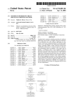
FIG. 1 is a block diagram of the voltage control portion
of the present invention.
FIG. 2 is a block diagram of the frequency portion of the
present invention.
FIG. 3 is a block diagram of the detection portion of the
present invention.
FIG. 4 is a block diagram of the reset unit of the present
invention.
FIG. 5 is a block diagram of the voltage converter of FIG.
2
FIG. 6 is a block diagram of the overrating voltage
protection device of the present invention.
FIG. 7 is an integral block diagram of the present inven
131 and the V10 voltage converter 132 is a V10 control unit
133 Which is controlled by the poWer pin VCC2DET#
de?ned by the CPU 10 in order to generate a sWitching
function similar to an ON/OFF sWitch. When the
VCC2DET# output is at high level, it represents that the
VCORE is equal to the V10. When the VCC2DET# output is
10
As shoWn in FIG. 6, in order to prevent the high voltage
of system poWer supply from being directly applied to the
15
CPU 10 due to the breaking doWn of the voltage converter
13 and thereby destroying the CPU 10, an overrating voltage
protection device 134 is placed betWeen the VCORE voltage
tion.
converter 131 and the CPU 10. The output of the V10 is
DETAILED DESCRIPTION OF THE
INVENTION
connected to the overrating voltage protection device 134.
The output of the overrating voltage protection device 134
and the output of the V10 voltage converter 132 are respec
tively connected to the CPU 10 to provide poWer to the CPU
In order to achieve the goal of plugging and immediately
playing, the technical means of the present invention is to
provide the settings in the system ?rmware (BIOS) set by the
user according to the species of the CPU. The settings
include tWo portions, i.e., the Working frequency portion and
at loW level, the VCORE is not equal to the V10 so as to meet
the requirements of using all species of CPUs having
different voltage levels.
25
Working voltage portion, for a speci?c CPU. In order to
eXplain the device of the present invention in detail and
10. The overrating voltage protection device 134 has a
control signal Which is connected to the soft sWitch pin
PS-ON of the ATX poWer supply connector 135. When the
level of the soft sWitch pin PS-ON is high, the ATX poWer
supply forcibly turns off the computer system. By using the
above characteristic, When the output voltage of the VCORE
conveniently, the integral block diagram of the circuit (FIG.
7) is divided into a voltage portion (FIGS. 1, 5 and 6) and
a Working frequency portion (FIGS. 2, 3, and 4).
voltage converter 131 is normal, the level of the output
As shoWn in FIGS. 1 and 7, the poWer pins VCC2DET#
maintained at loW level. When the VCORE voltage converter
131 breaks doWn so that a high voltage enters, the overrating
signal of the overrating voltage protection device 134 is
and VCC2HL# de?ned by the CPU 10 are used to control
voltage protection device 134 outputs a high level signal to
the voltage. The Working voltage portion comprises a stor
age device 11, an initial voltage controller 12 and a voltage
converter 13. The poWer pins VCC2DET# and VCC2HL#
the soft sWitch pin PS-ON in order to turn off the ATX poWer
35
are connected to the initial voltage controller 12 to output an
initial voltage to the voltage converter 13 so that the com
puter can boot. After the computer system boots and uses the
As shoWn in FIGS. 2 and 7, the technical means for
changing the Working frequency of the CPU 10 of the
present invention is to change the frequency of the CPU 10
and to change the multiple frequency ratio. The Working
Working voltage set by the system ?rmWare, via a bus 14 the
system ?rmWare transmits the setting voltage to the storage
frequency is changed by using a frequency generator 20
device to store the state set by the user. After the CPU 10 is
having a serial bus interface (in the Working eXample of the
present invention an I2C is used) through the transmission of
reset, the voltage converter 13 changes the initial voltage to
the Working voltage needed by the CPU 10 according to the
the serial bus interface Without the use of any eXternal
setting voltage.
As shoWn in FIG. 5, the Working voltage needed by the
CPU 10 is divided into VCORE and V10. The VCORE is the
Working voltage needed in operating the CPU 10. V10 is the
voltage used to control peripheral devices. The voltage
45
riZed as folloWs:
control pin so that the frequency generator 20 can generate
different Working frequencies to selectively control the
output of frequency output pin. When the computer boots,
the frequency setting by the system ?rmWare is transmitted
to the multiple frequency controller 22 via a bus 21. The
output of the multiple frequency controller 22 has a very
high output impedance so that the controller 22 does not
affect the multiple frequency ratio in the CPU 10. The
VCORE and V10 are determined based on the species of the
CPU. The voltage converter 13 includes a VCORE voltage
converter 131 and a V10 voltage converter 132 for changing
the setting voltage to a corresponding Working voltage
needed by the CPU 10. According to information provided
by the CPU manufacturers, the VCORE and V10 are summa
supply to forcibly turn off the computer, thereby the input
high voltage does not destroy the CPU 10.
frequency generated by the frequency generator 20 is input
55
1. For P54C, 6X86 and K5, the voltage VCORE and V10 in
into the phase latch loop (PLL) Which is built in the CPU 10.
The CPU Working frequency having a loW frequency is
formed by the frequency in association With the multiple
frequency ratio Which is built in of the CPU 10 to provide
to the computer for booting operation. When the user sets the
the inside of the CPU 10 Which are connected therebe
tWeen are equal.
Working speed of the CPU 10 through the system ?rmWare,
2. For P54CTB, the level of VCORE is equal to that of V10
HoWever, in the inside of the CPU 10, the VCORE is not
connected to the V10.
3. For P55C, K6, 6X86MX and 6X86L, the level of
VCORE is not equal to that of V10.
the system ?rmWare stores the setting data in the multiple
frequency controller 22. When the CPU 10 is reset again, the
multiple frequency controller 22 takes control of the value of
the multiple frequency ratio of the CPU 10, and outputs a
CPU multiple frequency control signal to the CPU 10. The
In the case that the mother board manufacturers do not
knoW the species of the CPU that is mounted on the mother
board selected by the user, the mother board should meet the
65
CPU frequency generated from the frequency generator 20
gives the CPU Working speed set by the user in the phase
latch loop inside the CPU 10. Then, the CPU 10 takes the
5,951,681
5
6
Working speed changed according to the CPU Working
directly set on the system ?rmWare Without the settings of
the jumper in order to achieve the goal of plugging and
immediately playing of a CPU. The device of the present
speed, as the Working frequency. For example, the speed set
by the user is the Working speed of Intel 200, then the
multiple frequency controller 22 changes the built-in mul
tiple frequency ratio to be 3, and the 66.667 MHZ frequency
invention also provides an overrating voltage protection
device for the poWer supply, and provides protection means
for updating the setting data after the CPU is removed from
the CPU socket. The method and device of the present
invention can maintain the stability of the computer system
during changing Working frequency and can provide a
suitable Working voltage based the species of CPU.
While the invention has been particularly shoWn and
described With reference to the preferred embodiments, it
Will be understood by those skilled in the art that various
changes in form and details may be made Without departing
from the spirit and scope of the invention. Although only the
generated in the frequency generator 20 is changed and
gives a 200 MHZ Working frequency in the phase latch loop.
(3x66.667 MHZ=200 MHZ)
FIG. 4 relates to a reset unit of the present invention. After
the user has set the settings on the system ?rmware and the
set Working frequency is generated, the CPU 10 transmits
this Working frequency to the system chip 23 via a bus. The
system chip 23 contains a decoder and stores the Working
frequency. The decoder decodes the address that stores the
Working frequency in order to generate a triggering signal 24
preferred embodiments of this invention Were shoWn and
Which is transmitted via an I/O port to the reset unit
actuation device 25 Which actuates the reset unit 26 in the
described in the above description, it is requested that any
system chip 23 in order to give a reset signal 27 transmitted
to the CPU 10. When the CPU 10 receives the reset signal
this invention be protected.
27, the loW speed frequency Which is originally used to boot,
is converted into the Working frequency Which is set up by
modi?cation or combination that comes Within the spirit of
I claim:
20
the user. Then the step of converting into the Working
frequency is done.
frequency and a Working voltage on a system ?rmWare, the
When the user sets the Working frequency and voltage on
the system ?rmWare, the computer starts to calculate based
on the settings. In other Words, if the user does not set them
Working frequency setting procedure comprising the steps
of:
changing a frequency by controlling a frequency genera
again in the system ?rmWare, the settings in the system
tor via a bus;
?rmWare are not changed. In some special cases, such as,
storing a frequency setting in a multiple frequency con
dismantling, changing the species of, and upgrading of the
troller;
CPU 10, the computer system does not knoW that the CPU
resetting the CPU so that the multiple frequency control
ler takes control of a CPU multiple frequency ratio in
is replaced by a neW one. If the user does not set the setting
data again, the Working frequency and voltage of CPU 10
Will be determined by the old settings. Thus, the computer
cannot boot because the frequency setting is too high, or the
CPU 10 is broken doWn because the Working voltage is too
1. A method of plugging and immediately playing a CPU
Which comprises a Working frequency setting procedure and
a Working voltage setting procedure for setting a Working
order to instruct the CPU to give a neW Working
35
high. In order to prevent the old Working frequency and
Working voltage from destructing the neW CPU 10 after the
frequency by the multiple frequency ratio;
and the Working voltage setting procedure comprising the
steps of:
storing a voltage setting from the system ?rmWare via the
bus;
old CPU is removed from the CPU socket 30 and a neW
outputting an initial voltage from an initial voltage con
troller Which is controlled by the CPU via a plurality of
different CPU 10 is inserted onto the CPU socket 30, in the
present invention, detection circuit Which comprises a detec
tion unit 32 and a sensor is provided. The sensor comprises
one pin 31 of the common grounding pins of the CPU socket
30 Which is isolated and connected to a detection unit 32,
pins; and
converting the initial voltage into the Working voltage by
means of a control of a voltage converter;
and a resistor 33 Which is connected to a poWer supply VCC.
When the old CPU 10 is mounted on the CPU socket 30, 45
Wherein the Working frequency and Working voltage of
the CPU are changed by the frequency and voltage
settings.
because the pin 31 and all the other common grounding pins
are grounded, the site of the pin 31 is grounded. When the
old CPU 10 is removed from the socket 30, the voltage level
of the pin 31 of the socket 30 is increased from grounding
2. The method of plugging and immediately playing a
CPU as claimed in claim 1, Wherein after the frequency and
voltage to VCC voltage so that the detection unit 32 can
detect the state (removed or inserted) of the CPU in order to
detect Whether the CPU 10 is removed from the socket 30 or
is inserted on the socket 30. When the detection unit 32 has
detected the state, the state is stored in a state storage unit 34,
and is transmitted to the system ?rmWare via an I/O port 35.
When the computer system is booted, the state is detected to
determine Whether the former state data should be aban
doned or not. If the state is changed, When the computer
system is booted, a Warning message is shoWn to the user.
50
Then, the user can set the state settings aneW to maintain the
aO
voltage settings are set on the system ?rmWare, the CPU is
booted by a loW frequency according to a built-in multiple
frequency ratio.
3. The method of plugging and immediately playing a
CPU as claimed in claim 1, Wherein according to species and
frequency of the CPU set on the system ?rmWare, the base
frequency corresponding to the settings is generated and
transmitted to the CPU.
4. The method of plugging and immediately playing a
CPU as claimed in claim 1, Wherein after the CPU receives
a base frequency and the multiple frequency ratio, the
stability of the computer system and to prevent the incorrect
Working frequency corresponding to the settings are set on
the system ?rmWare by a user, and after the resetting step,
setting from destroying the CPU 10. The sensor can further
comprise a state storage unit 34.
In conclusion, the present invention provides a method
the neW Working frequency is the Working frequency Which
is used for calculation operation and booting neXt time.
5. A device of plugging and immediately playing a CPU
and device of plugging and immediately play a CPU. After
m5
comprising a Working frequency portion and a Working
the CPU is mounted on the mother board by the user, the
voltage portion, Wherein the Working frequency portion
Working frequency and Working voltage of the CPU are
comprising:
5,951,681
8
7
8. The device of plugging and immediately playing a CPU
as claimed in claim 7, Wherein betWeen the VCORE voltage
converter and the V10 voltage converter is a V10 control unit
Which is controlled by a poWer pin de?ned by the CPU in
a frequency generator having a serial bus interface for
changing a frequency via the serial bus and transmitting
a changed frequency to the CPU;
a multiple frequency controller Which generates and
order to generate a sWitching function and to determine
Whether the voltage VCORE and V10 interact so as to meet the
latches a multiple frequency ratio according to a fre
quency setting set on a system ?rmware in order to
requirements of using all species of CPUs having different
voltage levels.
output a multiple frequency signal to the CPU so that
the CPU generates a Working frequency de?ned by the
system ?rmware based on the frequency generator and
the multiple frequency ratio; and
10
a reset unit Which generates a reset signal to the CPU so
that an original built-in multiple frequency ratio is
replaced by a neWly set multiple frequency ratio in
order to generate a Working frequency corresponding to
the frequency setting set on the system ?rmWare,
converter.
15
the Working voltage portion comprising:
device has a control signal Which is connected to a soft
set on the system ?rmWare and transmitted from a bus;
an initial voltage controller Which is controlled by a CPU
poWer control pin, the initial voltage controller output
25
the system ?rmWare;
Wherein after the frequency and voltage settings are set, the
Working frequency and voltage of the CPU are changed by
the settings so as to achieve the goal of plugging and playing
the CPU.
6. The device of plugging and immediately playing a CPU
to maintain the stability of a computer system and to prevent
35
prises a VCORE voltage converter and a V10 voltage con
verter Which respectively convert voltages VCORE and V10
needed by the CPU.
CPU as claimed in claim 11, Wherein the sensor comprises
socket Which is isolated and connected to a detection unit
and a resistor being connected to a poWer supply VCC, and
by detecting the voltage level of the sensing pin, the CPU
state can be determined.
13. The device of plugging and immediately playing a
CPU as claimed in claim 12, Wherein the sensor further
CPU receives the reset signal, a loW speed frequency Which
is originally used to boot, is converted into the Working
as claimed in claim 5, Wherein the voltage converter com
an incorrect setting from destroying the CPU.
12. The device of plugging and immediately playing a
one sensing pin of common grounding pins of the CPU
contains a decoder and stores the Working frequency, the
decoder decodes an address that stores the Working fre
quency in order to generate a triggering signal Which, via an
I/O port, is transmitted to the reset unit actuation means
Which actuates the reset unit in the system chip in order to
give a reset signal transmitted to the CPU, and When the
7. The device of plugging and immediately playing a CPU
CPU as claimed in claim 5, further comprising a detection
means for detecting Whether the CPU is removed or inserted
on a CPU socket and for determining Whether the setting set
before should be abandoned, Wherein the detection means
comprises a detection unit and a sensor, and if a CPU state
has been changed, the system ?rmWare sends a Warning
as claimed in claim 5, Wherein the reset unit comprises a
frequency Which is set up by a user.
sWitch pin of an ATX poWer supply connector, and When the
VCORE voltage converter breaks doWn so that a high voltage
occurs, the overrating voltage protection device outputs a
high level signal to the soft sWitch pin in order to turn off the
ATX poWer supply to forcibly turn off the CPU.
11. The device of plugging and immediately playing a
message upon booting so that a user can set the setting aneW
system chip and a reset unit actuation means, after the
settings are set on the system ?rmWare and the Working
frequency is generated, the CPU transmits this Working
frequency to the system chip via a bus, the system chip
10. The device of plugging and immediately playing a
CPU as claimed in claim 9, Wherein the overrating voltage
protection device is placed betWeen the VCORE voltage
converter and the CPU, the overrating voltage protection
a storage means for storing and latching a voltage setting
ting an initial voltage to the CPU for booting When the
CPU is booted; and
a voltage converter Which converts the initial voltage into
a Working voltage according to the voltage setting on
9. The device of plugging and immediately playing a CPU
as claimed in claim 5, Wherein the Working voltage portion
further comprises an overrating voltage protection device to
prevent high voltage of a system poWer supply from being
directly applied to the CPU due to breakdoWn of the voltage
45
comprises a state storage unit, the detection unit detects the
voltage level of the sensing pin and sends the CPU state to
the state storage unit, the state storage unit stores the state,
and the computer system can detect the CPU state via an I/O
port to determine Whether the setting set before should be
abandoned.