1
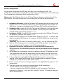
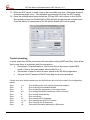
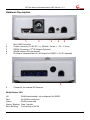
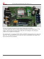
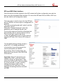
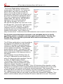
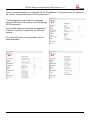
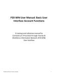
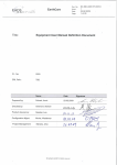
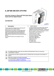
Manual IRTrans WiFi Version 1.01 IRTrans Manual Hardware/Setup WiFi Version 1.01 EU Declaration of Conformity For the following products IRTrans WiFI / IRDB we hereby declare that they conform to the declarations regarding Electromagnetic Compatibility as defined in DIN EN 55024 : 1998 + A1: 2001 + A2: 2003 DIN EN 55022 : 1998 limit class B + A1 : 2000 + A2 : 2003 Manual IRTrans System © 2012 IRTrans GmbH 2 IRTrans Manual Hardware/Setup WiFi Version 1.01 Initial Configuration For the initial configuration the IRTrans WiFi has to be connected via USB. The configuration can be done using the IRTrans GUI Client or the IRConfig Tool. The IRConfig Tool is available for Windows, LINUX and the Mac (OS/X). Please note: The IPAssign Tool for the IRTrans Ethernet devices cannot be used for the WiFi devices. The initial configuration can only be done via USB as described here. 1. Installation Windows: Install the Windows SW package that can be found on the IRTrans CD or on our Website (Setup.exe). The setup package also includes the USB Driver. During the installation select “IRTrans WiFi“ as the installed device. 2. Installation Mac: Install the IRConfig Tool and the USB driver. Both can be found in the “Mac” folder of the CD or on our website. The IRConfig tool needs JRE (Java Runtime environment) version >= 1.6. 3. Installation LINUX: The LINUX SW can also be found on the IRTrans CD and on our website. It needs a JRE version >= 1.6. 4. Connect the IRTrans WiFi to a suitable power supply (8-16V DC / >= 300mA) and with the supplied USB Cable to the computer. Now the USB Driver will be loaded automatically. Important: The IRTrans WiFi needs a power supply – it is not powered via USB. 5. Now the IRConfig program can be started via the Windows Menu. On the Mac it will be installed under “Programs”. On LINUX start irconfig.sh. 6. Important: During the configuration on other SW shall connect to the IRTrans device via USB as the USB port can only be opened by one program at a time. 7. On Windows the configuration can also be done by starting “IRTransServer USB“. The configuration can then be started using “Device Status” via Right click from the IR Menu (next to the clock). Both configuration methods have the same result. 8. In the configuration dialog (WLAN Tab) the WLAN parameters can now be entered. In any case the SSID and WLAN Preshared key are needed. All other settings can usually be left on their default values. 9. Due to security reasons we strongly suggest to use only WPA2 encryption on the access point. 10. There are some minor restrictions regarding the WLAN parameters: - WLAN Channel 14 is currently not supported - The max. length for the WLAN Preshared key is 31 characters. That has no implication on security – every key with a length of at least 15 characters assures the full WPA2 security. 3 IRTrans Manual Hardware/Setup WiFi Version 1.01 11. When an NTP server is used it has to be accessible any time. Otherwise dropped connections might occur. We therefore recommend not using the NTP setting. 12. Once the settings have been stored the IRTrans WiFi will connect to the WLAN. During that process the WLAN Status LED will blink green and red multiple times Once the device is connected to the WLAN the Status LED will be green. Trouble shooting In most cases the WLAN connection will work after entering SSID and Key. Here a few tips in case there is a problem with the connection: Sometimes it is problematic to use Access Points that have a hybrid B/G mode. If that is the case please select either B or G. Sometimes it helps to select a lower speed in the WLAN configuration Using a fixed IP instead of DHCP does help to fix some problems If there is an error when connecting to the WLAN there will be an error code in the configuration dialog: Error Error Error Error Error Error Error Error Error Error 4 1-3: 4: 5: 6/7: 8: 9: 10: 11-14: 15: 16: Error initializing the radio module (Hardware problem) Error scanning the available WLANs Error reading the parameters of the radio module Error setting the WLAN parameters (SSID, Channel) Error setting the WLAN key Error connecting Error setting the IP Parameter Error opening the UDP/TCP Sockets Error verifying the IP Parameter Connection procedure aborted by USB access IRTrans Manual Hardware/Setup WiFi Version 1.01 Hardware Description 1 2 3 4 5 1 2 3 4 5 Mini USB Connector Power connector (8-16V DC / >= 300mA / Center + / 5.0 - 2.1mm) nd RS232 Connector / 2 IR Output (Optional) WLAN Status LED (see below) IR Output (combined with 2nd IR Output for RS232 + 2nd IR; Optional) 6 Connector for external IR Receiver 6 WLAN Status LED Off Red Green Green / Blinking Red / Blinking WLAN deactivated / not configured (No SSID) No WLAN connection WLAN connected Data Transfer Connecting to WLAN 5 IRTrans Manual Hardware/Setup WiFi Version 1.01 The red circle marks the jumper for the external High power transmitter. The other jumpers are used to configure additional hardware options (RS232 port, 2nd IR Output). Those jumpers are set by factory and shall not be changed. Just setting the jumpers will not enable the HW options. All available ports / connections (WLAN, USB, and RS232 [if equipped]) can be used at the same time. The optional RS232 port can also be used for configuration and usage of the Device with the IRTrans Software. 6 IRTrans Manual Hardware/Setup WiFi Version 1.01 IRTrans WiFi Web Interface Once the device can be reached in the WiFi network all further configuration can also be done using the integrated Web interface. Of course the IRTrans SW via USB or WiFi can also be used for all configuration tasks. The login page is used to log in into the IRTrans device. Without a correct login no configuration is possible. The login is preconfigured with “admin” and the password “irtrans”. Using the “Change Password” menu the password can be changed by the user. For security reasons a session is disconnected automatically after 2 minutes without activity. Then a new login needs to be done. In case the password is lost it can be reset by using the IRTrans GUI Client or IRConfig via USB. The WLAN/IP Settings Dialog allows to set all WiFi / IP related parameters. In the bottom lines of the page all the current parameters are shown. By pressing „Store Configuration“ all parameters are stored in the EEPROM of the device. Important: When IP parameters are changed the WiFi connection will be reset on storing the parameters. That means the device will not be accessible for a few seconds. In case of wrong settings the device might not be reachable by WiFi any more. If that happens the settings can be corrected via USB. 7 IRTrans Manual Hardware/Setup WiFi Version 1.01 The Access Rights dialog configures the access rights of the device. If no values are entered here, any client can access the device. As soon as at least one value is entered only clients that fit into at least one of the entries are allowed to access the device. Each entry consists of an IP address and a subnet mask: 192.168.0.0 / 255.255.255.0 enables all clients within the network 192.168.0.x. An entry 192.168.0.1 / 255.255.255.255 allows only one client to use the IRTrans WiFi. The access rights are active for all TCP and UDP functions. To avoid a complete lock-out it is always possible to access the web front end from within the local network of the device – even if there is no entry for that subnet. Furthermore the USB connection can be used to unlock the device. Due to space and performance restrictions in an embedded device it is hardly possible to achieve a complete protection against hostile attacks. Therefore the IRTrans WiFi device should be protected from hostile environments (e.g. the Internet) using a firewall. The IR Relay configuration is used to configure the relaying of IR signals from one IRTrans LAN/WiFi to another. In general IR signals received by other IRTrans LAN/WiFi modules will be relayed automatically. This relaying works without a server – even with IRTrans devices without an integrated IR database. The exact configuration of the relaying is done in this dialog. In the list below “Accept IR Relay from“ all IRTrans IP Addresses can be entered from which IR relaying should be enabled. If the list is empty, all signals will be relayed. The list below “Send IR Relay to“ tells the system to which devices received IR codes should be relayed. Normally it is enough to enable the checkbox „Broadcast IR Relay“. Only if IR data should be relayed to routed networks it is important to enter a target address because broadcasts will not be routed. The IR receiving of the irserver is also done via that broadcasts. That means either broadcast has to be enabled or the address of the host running the irserver has to be in this list – otherwise the irserver will not receive IR codes from this IRTrans module. The UDP Broadcast fields are only used for modules with integrated IR Database. They define to which address and port formatted IR receive data has to be sent. The precise 8 IRTrans Manual Hardware/Setup WiFi Version 1.01 format of these telegrams is configured via the IR database. This function can, for example, be used to communicate with a Gira Homeserver™. The IR parameters can either be configured using the IRTrans GUI client or via the webpage “IR Configuration”. All the fields and their meanings are explained in detail in the User’s manual for the IRTrans system. Of course both ways of configuration can be used alternately 9 IRTrans Manual Hardware/Setup WiFi Version 1.01 If the IRTrans WiFi module has got the optional RS232 port the RS232 dialog can be used to configure the RS232 settings. The password used to login into the web configuration front end can be changed in the “Change Password” dialog. As usual the entry of the old and the new password has to be done here. Furthermore the new password has to be repeated. If the user has locked out himself due to a wrong password or configuration errors the configuration can corrected via USB using the GUI Client or IRConfig tool. The menu item “Logout” ends the current configuration session. Before any further configuration changes can be made a new login is needed. Via “Reboot System“ the IRTrans WiFi can be booted. 10 IRTrans Manual Hardware/Setup WiFi Version 1.01 Programming the IR Database (Only for devices with optional IR Database) Using Mode – Device database the integrated IR Database can be configured using the IRTrans GUI client. A remote control is selected with the right mouse button. Selected remote controls are shown red and bold. All selected remote controls with all their commands will be stored in the device database. The “Default Action” text box defines the string that will be sent via UDP when an IR command is received. If the field is empty, only commands with their own action will be sent via UDP. The following macros are available: %r Name of the remote control %c Name of the IR command %a Address of the device on the serial bus Carriage returns can be sent using “\r” and line feeds via “\n”. The checkbox “Device DB active“ allows to switch the IR Database on or off. Furthermore an individual string can be defined for each IR Command. After opening the remote control each command can be selected using the right mouse button. Now an ASCII or binary string can be stored. Binary data is stored via 2 digit Hex codes with a space as a separator (e.g. 20 43 0D 0A). This string will be send via UDP when the selected command is received. In the ASCII mode Carriage Return and Linefeed can be generated using “\r” and “\n”. Relay Control is not used with the IRTrans WiFi. 11 IRTrans Manual Hardware/Setup WiFi Version 1.01 Loading and Storing the Device Database The Device Database will always be stored on the server side. It will be stored in the remotes folder that is also used to store the IR Commands. Store Load Flash – Stores the device database using the given name – Loads the database definition – Transfers the device database to the flash memory of the device An arbitrary number of configurations can be stored on the server. However, only one active configuration can downloaded to the device. Of course an arbitrary number of remote controls and commands can be selected in the IR Database – as long as they fit into the 128k of memory inside the device. Using the optional integrated IR database The integrated IR database (optional) allows using the IRTrans modules with different clients without the IRTrans server SW. To allow this, parts of the irserver software have been integrated into the Firmware of the IRTrans WiFi modules. However, due to restricted resources when using a Microcontroller it is not possible to implement the whole irserver with some 1.000 lines of code. Therefore some functions are still only supported via the irserver. All functions that are needed for the normal use are of course included and will work with all IRTrans clients (irclient, IRTrans GUI Client, .NET DLL, Active-X Plugin, Girder Plugins, C DLL… ): Sending of IR Codes using the IR Database Direct sending of CCF Codes Receiving IR Codes and controlling the PC via IR signals List of remote controls List of commands for each remote control Learning of new IR commands is always done using the IRTrans server SW. Because of that approach all learned remote controls are stored on the server system and can be reused. Of course the remote database files (.rem files) are compatible with all other IRTrans devices (USB, RS232 etc.). Learning is therefore done in the following order: 1. 2. 12 Connection to the IRTrans server using the IRTrans GUI client Learning and testing of the IR Commands IRTrans Manual Hardware/Setup WiFi Version 1.01 3. Now the learned remote controls can be selected and transferred to the WiFi device. This is also done using the IRTrans GUI Client. Now all IRTrans clients can connect directly to the IRTrans WiFi module using the hostname or IP address of the WiFi module. When starting the IRTrans GUI client (irremote.exe) the IP address can be used as a parameter (e.g. “irremote 192.168.0.32“). Up to 4 clients can connect to a single IRTrans module. In addition multiple servers can use a single IRTrans WiFi module. Please consider that these functions are only available on WiFi modules with integrated IR database ! Using the WiFi module through different applications Different APIs are available for clients: 1. IRTrans TCP/IP Interface. The TCP/IP Interface uses TCP Port 21000 for communication. This TCP/IP interface is the standard interface that is also used by all IRTrans clients. This includes the GUI Client, the ASCII Client, Girder and all plugins for own applications (Active-X, DLL, .NET). This same interface is also integrated in the IRTrans server (irserver). 2. IRTrans UDP Interface. The UDP Interface uses ASCII strings to communicate. These strings are exchanged via UDP port 21000. This interface is also supported by the IRTrans server. This is the syntax of the UDP commands: snd <remote>,<command>,[l<led>],[p<port>] sndr <remote>,<command>,[l<led>],[p<port>] <remote> and <command> are the names of the remote control and command. sndccf <ccf hexstring>,[l<led>],[p<port>] sndccrf <ccf hexstring>,[l<led>],[p<port>] <ccf hexstring> CCF Hexstring in form of an ASCII String <led> allows to select the internal (i), external (e) or both (b) IR LEDs. nd 1 or 2 select a specific IR output (only devices with optional 2 output) <port> UDP port used to send an ACK („OK“ or „ERR“) to. Default is 21000. The r-versions (sndr, sndccfr) send the repeat codes (if available). 13 IRTrans Manual Hardware/Setup WiFi Version 1.01 3. IRTrans HTTP Interface. The HTTP Interface allows sending IR Codes stored in the IR Database using an HTTP / browser interface. Sending is done using a simple HTTP URL: http://192.168.0.32/send.htm?remote=<remote>&command=<command> The following parameters are supported: remote=<remote> command=<command> Names of remote control and command led=<ledselect> Selection of the IR LEDs (internal, external, both, 1, 2) quiet Instead of the status page an empty HTML page is returned back The WiFi module returns an HTML page that guides the browser back to the original page. This allows setup a simple remote control using static HTML pages that can be stored in files rather than a web server. This feature can easily be tested by entering the URL using a web browser. With all modes macros can be sent by separating multiple commands for one remote control with “;” A pause can be added by using “@p<timeout>;” (<timeout> = pause in ms). 14 IRTrans Manual Hardware/Setup WiFi Version 1.01 Declaration of Conformity According to 47CFR, Parts 2 and 15 for Peripherals Power Supplies used with Class B Personal Computers: We: Located at: IRTrans GmbH Einsteinstrasse 14, 85716 Unterschleissheim, Germany Declare under sole responsibility that the product identified herein, complies with 47CFR Parts 2 and 15 of the FCC rules as a Class B digital device. Each product marketed, is identical to the representative unit tested and found to be compliant with the standards. Records maintained continue to reflect the equipment being produced can be expected to be within the variation accepted, due to quantity production and testing on a statistical basis as required by 47CFR §2.909. Operation is subject to the following two conditions: (1) This device may not cause harmful interference, and (2) This device must accept any interference received, including interference that may cause undesired operation. The above named party is responsible for ensuring that the equipment complies with the standards of 47CFR §§15.101 to 15.109. Trade Name: IRTrans IR Control System Types or Model Numbers: IRTrans WiFi / WiFi IRDB Signature of Party Responsible: Printed name of Party Responsible: ___________________ Marcus Müller Executed on (Date), at (Place): 01-01-10, Unterschleissheim 15