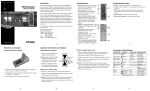
1
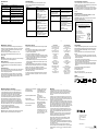
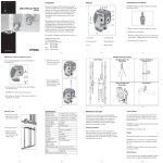
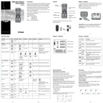
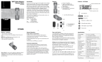
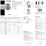
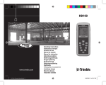
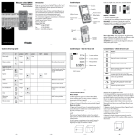
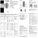
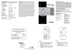
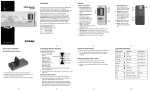
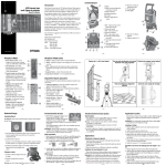
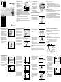
Features and Functions
LL500 Laser Level
User Guide
•
01. Power Button—turns the laser
2
on/off.
02. Handle—allows you to carry
3
the laser easily.
03. Battery Housing—holds four
1
4
D-cell alkaline or Ni-Cd
11
5
batteries.
10
6
04. Battery-Recharging Jack—is
7
the port that an optional battery
8
recharger plugs into.
9
05. Low-Battery LED—flashes
when the batteries need replacing or recharging.
06. Rotating Prism—spins at 600 rpm to transmit the laser signal.
07. Bull’s-Eye Level—provides an easy reference for leveling the laser.
08. Leveling Screws—turn clockwise/counterclockwise so the laser can
be leveled.
09. Leveling Base—supports the laser while it’s on the tripod. The
leveling base also allows you to use the laser freestanding.
10. Lighthouse—is a 360° exit window for the laser beam. The
lighthouse is sealed and protects the internal components from
the environment.
11. Out-of-Level LED—flashes when the laser is out of its self-leveling
range.
12. X Axis Calibration Screw—
allows the X axis of the laser
to be adjusted so that the
laser beam is level.
13. Y Axis Calibration Screw—
allows the Y axis of the laser
to be adjusted so that the
laser beam is level.
14. 5/8-11 Tripod Mount—
allows the laser to be
attached to a standard
5/8-11 construction tripod.
12
13
2. Install/remove the batteries
Note: When installing the batteries, be sure to note the positive (+)
and negative (–) diagram inside the housing.
Note: The laser has reverse-polarity protection. If the batteries are
put in wrong, no damage occurs to the laser but it does not work.
Allow it one minute to recover after the batteries have been installed
correctly.
3. Put the battery housing in place and reinstall the screws.
14
Recharging the Batteries
Several optional battery rechargers are available, including ones that plug
into a wall outlet and one that uses solar power.
If you use the A/C battery rechargers, such as Model 1041/1041-E
(110/220 V) or Smart Charger Model 1041S/SE/SEND, N, NE,
NENG (110/220 V), recharge the laser overnight after every third day
of use. More frequent recharging may be needed if you use the laser for
long periods during the day or in colder climates.
Note: Do not recharge alkaline batteries. Trying to recharge them does
not damage the laser but doing so might blow the battery-protection
fuse in the battery pack.
How to Use the Laser System
Batteries
Installing/Removing the Batteries
1. Turn battery-housing
screws counterclockwise and
remove the battery housing. A
universal key (supplied) or coin
can be used to turn the screws.
www.trimble.com
–2–
–3–
–4–
Setting Up and Leveling the Laser
Recharging the Batteries (cont.)
1. Plug the battery recharger’s
plug into the laser’s battery
recharging jack.
2. Plug the battery recharger into
the wall outlet.
Note: A full charge will be
reached in 12-14 hours or 10
hours using the smart charger.
If you use the Model 341 solar
recharger, the laser must be
equipped with fully charged
Ni-Cd batteries. Using the soar
panel eliminates the need for an
A/C recharger.
1. Plug the solar panel’s plug
into the laser’s battery
recharging jack.
Determining the Height of Instrument (HI)
1. Set up a tripod to the height
appropriate for your
application needs.
2. Insert the 5/8-11 tripod screw
into the laser’s 5/8-11 threaded
insert.
Note: The laser can also be
attached to a column clamp or
other mounting device.
3. Turn the screw to hold the laser securely in place.
4. Press the power button.
Note: When the laser is initially turned on, the out-of-level LED
flashes to show that the laser needs leveling.
5. Using the left-thumb rule (see
Y+
the Note that follows), turn
both X axis screws equal
amounts in opposite directions
XX+
to move the bubble toward the
center of the bull’s-eye.
Y-
Note: Left-thumb rule—both
thumbs in, both thumbs out,
the bubble follows the left
thumb.
6. Observe the location of the
bubble (top or bottom of the
bull’s-eye) and using the leftthumb rule, turn the Y axis
screw to move the level bubble
so that it is centered in the
bull’s-eye.
Note: When the laser is level,
the bubble is centered in the
bull’s-eye and the out-of-level LED stops flashing and the laser’s rotor
begins rotating.
Note: If the laser is knocked out of its self-leveling range, the out-oflevel LED start flashing, the rotor stops, and the beam reference plane
turns off.
7. To restore level, simply re-level the laser and check your initial
reference elevation.
Note: The unit may also be set free-standing on any stable surface.
The height of instrument (HI) is the elevation of the laser’s beam. The
HI is determined by adding the grade-rod reading to a benchmark or
known elevation.
1. Set up and level the laser.
2. Attach the receiver to a grade rod and turn on the receiver.
3. Place the grade rod on a job-site benchmark (BM) or known
elevation.
4. Slide the receiver up/down the grade rod until the LCD shows an
on-grade reading.
5. Add the grade-rod reading to the benchmark to determine the height
of instrument.
Example: Benchmark elevation = 100.23 ft (30.55 m)
On-grade rod reading = + 4.34 ft (1.32 m)
Height of instrument = 104.57 ft (31.87 m)
6. Use this HI as a reference for all other elevations.
Height of Instrument (HI)
HI
Rod Reading
4.34 ft (1.32 m)
Benchmark
100.23 ft (30.55 m)
HI = Rod Reading + Benchmark
HI = 4.34 ft + 100.23 ft = 104.57 ft (1.32 m + 30.55 m = 31.87 m)
–5–
–6–
–7–
–8–
Checking Calibration
To check the horizontal
calibration, you’ll need a tripod
with a 5/8-11 threaded mount,
hand-held receiver, and 1/16 in.
(1.5 mm) diameter pin or small
nail. If you need to adjust the
calibration, having another person
to help saves time.
Y+
X-
X+
Y-
2. Raise/lower the receiver until
you get an on-grade reading for
the –Y axis. Using the on-grade
marking notch as a reference,
make a mark on the wall.
Note: For increased precision,
use the fine-sensitivity setting
(+1/16 in./ +1.5 mm) on the
receiver.
3. Rotate the laser 180° (+Y axis
toward the wall) and re-level
the laser.
1. Set up and level the laser 100 ft
(30 m) from a wall.
-Y
5. Measure the difference between
the two marks. If they differ
more than 1/8 inch at 100 feet
(3.0 mm at 30 m), the laser
needs calibrating.
-Y
> 1/8 in. (> 3.0 mm)
Y1
100 ft (30 m)
6. To correct for a calibration
error, position the receiver
at the midpoint of the two
elevation marks on the wall.
Note: Although you can
calibrate the laser by yourself,
having another person to help
saves time.
+Y
Y1
100 ft (30 m)
100 ft (30 m)
4. Raise/lower the receiver until
you get an on-grade reading for
the +Y axis. Using the on-grade
marking notch as a reference,
make a mark on the wall.
Y2
+Y
Y2
Y2
Y3
Y1
7. To adjust the calibration,
insert a nail (1/16 in. or 1.5 mm
diameter) into the opening in
the calibration screw and turn
the screw in the appropriate
direction
Note: The arrows on the
display show which direction
the calibration screws need
turning. An up arrow on the
receiver indicates that the
Y axis calibration screw needs
to be turned clockwise to
lower the laser plane. A down
arrow on the receiver indicates
that the Y axis calibration
screw needs to be turned
counterclockwise to raise
the laser plane.
8. Rotate the laser 180° back to
the original face. Make sure
this axis is less than 1/16 in.
(1.5 mm) from the midpoint
line.
Note: If additional adjustment
is required, repeat steps 2-7
above.
9. After adjusting the Y axis,
rotate the laser 90°. Repeat
steps 2-8 starting with the
–X axis facing the wall.
Y3
Up arrowturn calibration
screw clockwise
– 10 –
– 11 –
Down arrow- turn
calibration screw
counter clockwise
-Y
100 ft (30 m)
100 ft (30 m)
–9–
Y3
– 12 –
Specifications
Troubleshooting
Claim for Damage in Shipment
Laser
If none of the following techniques corrects the problem, take your
system to a local Trimble dealer or authorized service center for
evaluation or repair.
The LL500 laser system includes a laser, receiver, operator’s manual,
laser safety kit, carrying case, and alkaline batteries. Optional accessories
include a scope and battery recharger.
You should inspect your laser system as soon as you receive it. It has
been packaged for safe delivery. If it is damaged in any way, immediately
file a claim with the carrier or, if insured separately, with the insurance
company.
Laser Type/Classification
Self-Leveling Range
Manual Leveling Method
Horizontal Accuracy
Power Source
Battery Life (68˚ F / 20˚ C)
Operating Diameter
Operating Temperature
670 nm visible, Class II
±11 arc minutes
Three-screw leveling base with bull’s-eye
circular bubble and out-of-level LED
±10 arc seconds over temperature
<±1/16 in. per 100 ft (<±1.5 mm per 30 m)
4 D-cell alkaline or Ni-Cd (4.4 Ah) batteries
Alkaline: 80 hours
Ni-Cd: 27 hours
1600 ft (500 m)
–4 °F to 122 °F (–20 °C to 50 °C)
Problem
Laser will not operate
Laser out-of-level indicator
does not shut off
Laser not accurate
Solution
• Press power button.
• Check or replace batteries.
• Make sure the battery contacts
are clean.
• Make sure the battery housing is
securely in place.
• Return the laser to an authorized
service center for inspection.
• Make sure the laser setup is stable.
• Make sure the leveling screws
are free to turn.
• Re-level the laser and make sure
the bubble is centered in bull’s-eye
level vial.
• Return the laser to an authorized
service center for inspection.
• Check and adjust the laser’s
calibration as needed.
• Return the laser to an authorized
service center for inspection.
Problem
Low-battery LED is flashing
The laser levels, the rotating
prism turns, but the laser
beam does not come on
The receiver does not detect
the laser beam at long range
Batteries do not charge
Solution
• Replace or recharge the batteries.
• Return the laser to an authorized
service center for inspection.
• Clean the lighthouse and recheck
the receiver distance.
• Return the laser to an authorized
service center for inspection.
• Make sure the laser is not equipped
with alkaline batteries.
• Make sure the Ni-Cd batteries are
correctly installed.
• Replace the Ni-Cd batteries with
new ones.
• Replace the recharger.
Safety Information
Included in this manual are CAUTIONS and Notes. Each of these
words represents a level of danger or concern.
A CAUTION indicates a hazard or unsafe practice that could result in
minor injury or property damage.
A Note indicates important information unrelated to safety.
Notice to Our European Union Customers
For product recycling instructions and more information,
please go to: www.trimble.com/environment/summary.html
Recycling in Europe
To recycle Trimble WEEE,
call: +31 497 53 2430, and
ask for the “WEEE associate,” or
mail a request for recycling instructions to:
Trimble Europe BV
c/o Menlo Worldwide Logistics
Meerheide 45
5521 DZ Eersel, NL
– 13 –
– 14 –
Maintenance and Care
Request for Service
You will get years of service from the leveling system by following the
maintenance and care recommendations in this manual. Carry the laser
in its moisture-resistant, field-tested carrying case to safely move the
laser from one job to another.
However well the product is designed, mishaps do occur. The
most common problems associated with these are covered in the
following areas.
Our goal is to provide prompt and efficient service through competent
service dealers.
Before returning your system for repair, be sure to do the following:
1. Put a note into the package identifying yourself as the owner.
2. Explain the operating difficulty.
3. Include a return address and phone number.
4. If the laser is in warranty, provide verification of the date of purchase.
5. Pack the equipment securely for shipment in its original carrying case.
6. Return the equipment prepaid and insured to your local dealer or
authorized Trimble Service Center.
7. Request estimate of charges for non-warranty or other service work
before repair begins. If estimates are not requested, repair work will
begin immediately.
All certified outlets have factory-trained personnel and use authorized
replacement parts to ensure proper and quick return. For long-distance
shipments, UPS, 2nd-Day Air, or airfreight is recommended.
Except for one-way transportation charges, there will be no charge for
repairs caused by problems due to defective materials and/or
workmanship under warranty.
To locate your local dealer or authorized Trimble Service Center world
wide for service, accessories, or spare parts, contact one of our offices
listed below.
Storage
CAUTION: Do not store the laser in a wet carrying case. If the case gets
wet, open it and let it dry before storing the laser.
Battery Disposal
Some states and local areas have regulations regarding the disposal of
rechargeable batteries. Be sure that replaced batteries are disposed of
properly.
System Cleaning
Use only a good-quality glass cleaner and a soft cloth to clean all external
optical components. A dry cloth used on the laser exit windows may
scratch or damage the glass surfaces.
Monthly, wipe off with a moist, clean cloth any dust or dirt from the
laser’s outer surface, inside the battery housing, and within the leveling
base. Blow off any loose debris before cleaning any surfaces to prevent
scratching of optical surfaces.
– 15 –
North America
Trimble Construction Division
5475 Kellenburger Road
Dayton, Ohio 45424-1099
U.S.A.
(800) 538-7800 (Toll Free)
+1-937-245-5600 Phone
+1-937-233-9004 Fax
– 16 –
Africa & Middle East
Trimble Export Middle-East
P.O. Box 17760
Jebel Ali Free Zone, Dubai
UAE
+971-4-881-3005 Phone
+971-4-881-3007 Fax
Asia-Pacific
Trimble Navigation
Australia PTY Limited
Level 1/120 Wickham Street
Fortitude Valley, QLD 4006
AUSTRALIA
+61-7-3216-0044 Phone
+61-7-3216-0088 Fax
Europe
Trimble GmbH
Am Prime Parc 11
65479 Raunheim
GERMANY
+49-6142-2100-0 Phone
+49-6142-2100-550 Fax
Latin America
Trimble Navigation Limited
6505 Blue Lagoon Drive
Suite 120
Miami, FL 33126
U.S.A.
+1-305-263-9033 Phone
+1-305-263-8975 Fax
China
Trimble Beijing
Room 2805-07, Tengda Plaza,
No. 168 Xiwai Street
Haidian District
Beijing, China 100044
+86 10 8857 7575 Phone
+86 10 8857 7161 Fax
www.trimble.com.cn
Laser Safety
This laser complies with all applicable portions of Title 21 of the code of
Federal Regulations, Department of Health and Human Services, Food
and Drug Administration (Federal Register, Volume 50, Number 161,
August 20, 1985).
As with any visible laser device, the following safety rules should be
observed:
• Never look directly into a laser beam or point the beam into the eyes
of others. Set the laser at a height that prevents the beam from shining
directly into people’s eyes.
• Do not remove any warning signs from the laser.
• Use of this product by people other than those trained on this product
may result in exposure to hazardous laser light.
• If initial service is required, which results in the removal of the outer
protective cover, removal must only be performed by factory-trained
personnel.
Questions about laser safety should be addressed to:
Trimble Navigation Limited
5475 Kellenburger Road
Dayton, OH 45424-1099 U.S.A.
Attention: Quality Assurance Group, Laser Safety Officer
Labels
Labels required for this product:
5475 Kellenburger Rd.
Dayton, Ohio 45424-1099 U.S.A.
CAUTION
COMPLIES WITH 21 CFR 1040 AS APPLICABLE
✔
N324
S/N
– 17 –
EMC Declaration of Conformity
This laser has been tested and found to comply with the limits for
a Class B digital device for radio noise for digital apparatus set out
in the Radio Interference Regulations of the Canadian Department
of Communication, and is pursuant to part 15 of the Federal
Communication Commission (FCC) rules. These limits are designed
to provide reasonable protection against harmful interference in a
residential installation. This laser generates radio frequency. If it’s
not used in accordance with the instructions, it may cause harmful
interference to radio or television reception. Such interference can be
determined by turning the laser off and on. You are encouraged to try
eliminating the interference by one or more of the following measures:
• Reorient or relocate the receiving antenna.
• Increase the separation between the laser and the receiver.
For more information, consult your dealer or an experienced
radio/television technician.
CAUTION: Changes or modifications to the laser that are not expressly
approved by Trimble could void authority to use the equipment.
– 21 –
– 18 –
Application of Council Directive(s):
Manufacturer’s Name:
Manufacturer’s Address:
European Representative Address:
Model Number(s):
Conformance to Directive(s):
Equipment Type/Environment:
Product Standards:
89/336/EEC directive on EMC
Trimble Navigation Limited
5475 Kellenburger Road
Dayton, Ohio 45424-1099
U.S.A.
Trimble GmbH
Am Prime Parc 11
65479 Raunheim, Germany
LL500
EC Directive 89/336/EEC using
EN55022 and EN50082-1
ITE/residential, commercial
& light industrial
Product meets the limit B
and methods of EN55022
Product meets the levels and
methods of IEC 801-2, 8 kV air,
4 kV contact IEC 801-3, 3 V/m
26 to 1000 MHz 80%, @ 1 kHz
IEC 801-4, ac leads 2 kV
– 22 –
LASER LIGHT
MFG.
DO NOT STARE INTO BEAM
MODEL:
– 19 –
Diode <3mW @ 635-670 nm
CLASS II LASER PRODUCT
DANGER
LASER LIGHT
WHEN OPEN.
AVOID DIRECT
EYE EXPOSURE
– 20 –
Warranty
Trimble warrants the LL500 laser to be free of defects in material and
workmanship for a period of two years. This warranty period is in effect from
the date the system is delivered by Trimble or its authorized Dealer to the
purchaser, or is put into service by a Dealer as a demonstrator or rental
component.
Additionally, items covered by the standard Trimble one-year warranty are the
accessories. All other components not manufactured Trimble but sold as a part
of the system such as tripods and grade rods, will carry a 90-day warranty or the
manufacturer’s warranty, whichever is greater.
Trimble or its Authorized Service Center will repair or replace, at its option, any
defective part of components of which notice has been given during the warranty
period. A Warranty Registration Card must be filled out properly and on file
with Trimble Service Department before warranty repair or replacement can be
approved. Travel and per diem expenses, if required, to and from the place where
repairs are made will be charged to the purchaser at the prevailing rates.
Customers should send products to the nearest Authorized Factory Service
Center for warranty repairs, freight prepaid. In countries with Trimble Service
Subsidiary Centers, the repaired products will be returned to the customer,
freight prepaid.
Any evidence of negligent, abnormal use, accident, or any attempt to repair
equipment by other than factory-authorized personnel Trimble certified or
recommended parts, automatically voids the warranty.
Special precautions have been taken to ensure the calibration of the laser;
however, calibration is not covered by this warranty. Maintenance of the
calibration is the responsibility of the user.
The foregoing states the entire liability of Trimble regarding the purchase and
use of its equipment. Trimble will not be held responsible for any consequential
loss or damage of any kind.
This warranty is in lieu of all other warranties, except as set forth above,
including an implied warranty mechantability of fitness for a particular purpose,
is hereby disclaimed. This warranty is in lieu of all other warranties, expressed
or implied.
– 23 –
Trimble Construction Division
5475 Kellenburger Road
Dayton, Ohio 45424-1099
U.S.A.
+1-937-245-5600 Phone
www.trimble.com
✔ N324
© 2002–2005, Trimble Navigation Limited. All rights reserved.
Reorder PN 1044-0050 Rev. C (07/05)