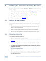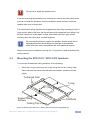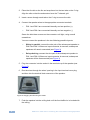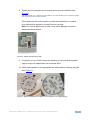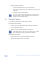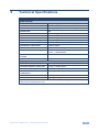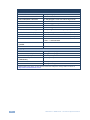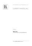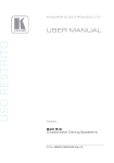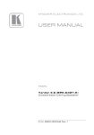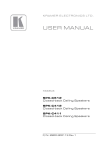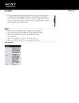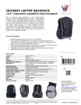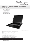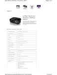
1
K R A ME R E LE CT R O N IC S L T D . USER MANUAL MODELS: SPK-C411 Closed-back Ceiling Speakers SPK-C412 Closed-back Ceiling Speakers P/N: 2900-300188 Rev 1 This page is intentionally left blank Contents 1 Introduction 1 2 2.1 Getting Started Achieving the Best Performance 2 2 3 Overview 3 4 Your Closed-back Ceiling Speakers 5 5.1 5.2 5.3 5.4 Installing the Closed-back Ceiling Speakers Choosing the Best Location Cutting the Ceiling Tile Mounting the SPK-C411 / SPK-C412 Speakers Painting the Speaker 6 6 6 7 10 6 Technical Specifications 11 4 Figures Figure 1: SPK-C411 / SPK-C412 Closed-back Ceiling Speakers in a Boardroom Setup Figure 2: SPK-C411/ SPK-C412 Closed-back Ceiling Speaker Figure 3: Closed-back Ceiling Speaker Schematic Diagram Figure 4: Mounting the SPK-C411 / SPK-C412 Closed-back Ceiling Speakers Figure 5: Plugging and Securing the Cable Figure 6: Tighten the Mounting Tabs Figure 7: Adjust Tap Selector (for SPK-C411 and SPK-C412, Respectively) SPK-C411 / SPK-C412 – Contents 3 4 5 7 8 9 9 i This page is intentionally left blank 1 Introduction Welcome to Kramer Electronics! Since 1981, Kramer Electronics has been providing a world of unique, creative, and affordable solutions to the vast range of problems that confront video, audio, presentation, and broadcasting professionals on a daily basis. In recent years, we have redesigned and upgraded most of our line, making the best even better! Our 1,000-plus different models now appear in 11 groups that are clearly defined by function: GROUP 1: Distribution Amplifiers; GROUP 2: Switchers and Routers; GROUP 3: Control Systems; GROUP 4: Format/Standards Converters; GROUP 5: Range Extenders and Repeaters; GROUP 6: Specialty AV Products; GROUP 7: Scan Converters and Scalers; GROUP 8: Cables and Connectors; GROUP 9: Room Connectivity; GROUP 10: Accessories and Rack Adapters and GROUP 11: Sierra Products. Congratulations on purchasing your Kramer SPK-C411 and SPK-C412 Closed-back Ceiling Speakers, which are ideal for the following typical applications: • Boardrooms • Presentation venues • Conference rooms • Training rooms • Educational classrooms • Hotel lobbies The package includes the following items: • A pair of SPK-C411 and/or SPK-C412 speakers • Mounting kit • This user manual i SPK-C411 and SPK-C412 are designed for indoor dry locations and are suitable for use in air handling spaces (plenum spaces). SPK-C411 / SPK-C412 - Introduction 1 2 Getting Started We recommend that you: Unpack the equipment carefully and save the original box and packaging • materials for possible future shipment • Review the contents of this user manual • Use Kramer high-performance high-resolution cables i 2.1 Go to http://www.kramerelectronics.com to check for up-to-date user manuals, application programs, and to check if firmware upgrades are available (where appropriate). Achieving the Best Performance To achieve the best performance: Use only good quality connection cables (such as the Kramer BC-2S) to • avoid interference, deterioration in signal quality due to poor matching, and elevated noise levels (often associated with low quality cables) • Do not secure the cables in tight bundles or roll the slack into tight coils • Avoid interference from neighboring electrical appliances that may adversely influence signal quality Position your Kramer SPK-C411 / SPK-C412 away from moisture, • excessive sunlight and dust i To ensure that you obtain the best sound results, do not open the housing of the passive speaker or the active speaker. UL2043 – Fire Test for Heat and Visible Smoke Release for Discrete Products and their Accessories Installed in Air-Handling Spaces. 2 SPK-C411 / SPK-C412 - Getting Started 3 Overview The SPK-C411 / SPK-C412 Closed-back Ceiling speakers consist of a pair of high performance closed back speakers. The pair can be mounted on the ceiling, as well as via a ceiling mounting kit used to safely secure the speakers to the ceiling. The speakers are defined in the following table: Name Diameter [ " ] Impedance [ Ω ] Closed-back Depth [ " ] SPK-C411 4 4 4 SPK-C412 4 8 4 Figure 1 shows an example of how the SPK-C411 / SPK-C412 Closed-back Ceiling speakers can be installed in a boardroom setup: Figure 1: SPK-C411 / SPK-C412 Closed-back Ceiling Speakers in a Boardroom Setup SPK-C411 / SPK-C412 - Overview 3 4 Your Closed-back Ceiling Speakers Figure 2 defines the SPK-C411 / SPK-C412. Figure 2: SPK-C411/ SPK-C412 Closed-back Ceiling Speaker The following table defines the Closed-back Ceiling speaker hardware items (per speaker pair) for each model in the series: Description A pair of ceiling speakers (one shown) Two grilles (one shown) Cutout template This table defines the ceiling mounting kit items: Four support ring screws 4 Two ceiling support rings (C-ring) – one shown Two pairs of tile rails – one of a pair shown SPK-C411 / SPK-C412 - Your Closed-back Ceiling Speakers Each Closed-back Ceiling speaker is supported by a C-ring and two tile rails. The tile rails prevent the speakers from falling if the tile itself comes out or falls apart, as their ends catch onto the T-grid. When mounting onto the ceiling tiles, use both supports. When mounting onto a sheetrock ceiling, the C-ring alone is used to reinforce the ceiling material. i Be sure that the tiles can support the speaker. Smaller sized tiles or fiberglass-type tiles cannot support the weight of the speakers. When this is the case, the speakers will need additional support. Figure 3 shows a schematic diagram of the Closed-back Ceiling speaker: Figure 3: Closed-back Ceiling Speaker Schematic Diagram SPK-C411 / SPK-C412 - Your Closed-back Ceiling Speakers 5 5 Installing the Closed-back Ceiling Speakers This section explains how to install the SPK-C411 / SPK-C412 closed-back ceiling speakers, that is: 5.1 • Choosing the best place to locate your speakers (see Section 5.1) • Cutting the ceiling tile (see Section 5.2) • Mounting the Speakers (see Section 5.3) • Painting the speakers (see Section 5.4) Choosing the Best Location Ideally, locate the speakers above the main listening area. Before doing so, be sure that: • The desired location is free of obstructions, such as electrical piping, AC ducts or water lines, and so on 5.2 • There is enough space behind the mounting surface for the speakers • The rear side of the speaker is not blocked by wall studs or other objects Cutting the Ceiling Tile To cut the ceiling tile, do the following: 1. Remove the circle in the supplied template. Keep this template for later use as a mask, as you may want to paint the speakers (see Section 5.4) 2. Mark the opening in the correct location by tracing the hole in the template. 3. Cut out the hole according to the template or with a circular cutter set to the appropriate cutout size. Initially, you can cut a smaller area inside the marked hole just to be sure that the space above the speakers is clear 4. Route the wiring from the amplifier to the speakers’ cutout holes, taking care not to place them next to electrical wires or at least at a distance of about two feet from an AC line. 6 SPK-C411 / SPK-C412 - Installing the Closed-back Ceiling Speakers ! Do not nail or staple the speaker wires. If you are mounting the speakers onto a ceiling tile, remove the ceiling tiles where you plan to install the speakers. Use the template to trace and then cutout the speaker hole over an empty box. The closed-back ceiling speakers are supported by the ceiling mounting kit (two Crings and two pairs of tile rails; the tile rails prevent the speakers from falling if the tile itself comes out or falls apart, as their ends catch onto the T-grid). When mounting onto the ceiling tiles, use both supports. i Be sure that the tiles can support the speaker. Smaller sized tiles or fiberglass-type tiles cannot support the weight of the speakers. When this is the case, the speakers will need additional support. When mounting onto a sheetrock ceiling, the C-ring alone is used to reinforce the ceiling material. 5.3 Mounting the SPK-C411 / SPK-C412 Speakers To mount the closed-back ceiling speakers, do the following: 1. Place the C-ring over the hole cut in the ceiling tile (on the “ceiling” side). Place it around the hole so that the tabs are located in parallel to the tile edges. T-channel Grid C-ring Support Ring Screws Ceiling Tile Tile Rails Figure 4: Mounting the SPK-C411 / SPK-C412 Closed-back Ceiling Speakers SPK-C411 / SPK-C412 - Installing the Closed-back Ceiling Speakers 7 2. Place the tile rails on the tile and snap them into the two tabs on the C-ring. Align the rails so that the ends extend over the T-channel grid. 3. Insert a screw through each tab on the C-ring to secure the rails. 4. Connect the speaker wires to the appropriate connector terminals: PIN 1 and PIN 2 are connected internally and are positive (+) PIN 3 and PIN 4 are connected internally and are negative (-) Screw the hold-down screws on the connector until tight, using a small screwdriver. You can connect the speakers in the two following possible layouts: Wiring in parallel: connect the wire pair of the subsequent speaker to PIN 2 and PIN 3. When one input connector is removed, subsequent speakers will remain connected (see Figure 3) Daisy-chaining: connect the wire pair of the subsequent speaker to PIN 1 and PIN 4. When one input connector is removed, subsequent speakers will be disconnected (see Figure 3) 5. Plug the connector into the socket in the terminal cup of the speaker (see Figure 5). 6. Run the wires through the wires’ opening in the input terminal cover plug and then into the terminal block connector of the speaker. Figure 5: Plugging and Securing the Cable 7. Push the speaker into the ceiling hole until the front baffle rim is leveled with the ceiling. 8 SPK-C411 / SPK-C412 - Installing the Closed-back Ceiling Speakers 8. Tighten the mounting tabs by turning the screw counter clockwise (see Figure 6). The first quarter turn, rotates the tab outwards, and the following turns tighten the tabs to the rear side of the ceiling surface When tightening the mounting tabs, the tabs automatically turn outward, thus clamping the speaker to the wall from its rear side. Note: Do not over-tighten the screws. It may cause damage to both the speakers and the surface. Figure 6: Tighten the Mounting Tabs 9. If required, you can further secure the speaker by connecting the speaker support ring to an independent secure anchor point. 10. Adjust each speaker to the appropriate tap setting before installing the grille (see Figure 7). Figure 7: Adjust Tap Selector (for SPK-C411 and SPK-C412, Respectively) SPK-C411 / SPK-C412 - Installing the Closed-back Ceiling Speakers 9 11. Install the grilles to the speakers: Push the grille fastener into the hole in front of the baffle Press the grille into place until the front of the grille is flush with the rim of the baffle i 5.4 Check that the grille is securely seated To remove the grille, insert two bent paper clips into the holes in the grille and carefully pull it down. Repeat this around the perimeter of the grille until it is completely removed. Painting the Speaker You can paint the speakers before or after they are installed. When painting before installation: Clean the rim and grille with mineral spirits or other light solvent that is • unlikely to damage the surface Spray with color by holding the spray can at an angle of 45° • i When spraying the grille, take care not to clog the holes in the grille as this will greatly reduce the sound quality of the speakers. When painting after installation: 10 • Use the circle that you cut out of the template as a paint mask • After you finish painting, remove the paint mask SPK-C411 / SPK-C412 - Installing the Closed-back Ceiling Speakers 6 Technical Specifications SPK-C411 Audio and Power DESCRIPTION: 2-way ceiling speakers with metal back can HIGH FREQUENCY DRIVER: 1/2" MYLAR dome tweeter LOW FREQUENCY DRIVER: 4” Polypropylene cone with rubber edge woofer IMPEDANCE: 4Ω DISPERSION COVERAGE: 75˚ - 100° @(2000Hz) CROSSOVER FREQUENCY: 6000Hz NOMINAL SENSITIVITY: 84dB SPL @1m, 1W DIRECTIVITY FACTOR (Q): 5.7 (averaged 100Hz-10kHz); 6.8 (2kHz) DIRECTIVITY INDEX (DI): 6.5dB (averaged 100Hz-10kHz); 4.8dB (2kHz) FREQUENCY RESPONSE: 75Hz to 20kHz INPUT POWER: 30W RMS; max. 40W, continuous load (24hr) 30W TRANSFORMER: 70V – 3.7W/7.5W/15W/30W 100V – 7.5W/15W/30W RECOMMENDED AMPLIFIER POWER: 20W INPUT CONNECTOR: Terminal block Shipping and Installation WEIGHT PER SINGLE SPEAKER: 2.75kg (6.06lbs) approx. SHIPPING WEIGHT (FOR PAIR): 7.9kg (17.42lbs) approx. DIMENSIONS (OD): 25.1cm (9.88") CUT OUT SIZE (MOUNT DIMENSION): 22.3cm (8.78") MOUNT DEPTH: 11cm (4.33") ACCESSORIES: Ceiling mounting kit Specifications are within a 10% tolerance and are subject to change without notice at http://www.kramerelectronics.com SPK-C411 / SPK-C412 - Technical Specifications 11 SPK-C412 Audio and Power DESCRIPTION: 2-way ceiling speakers with metal back can HIGH FREQUENCY DRIVER: 1/2" MYLAR dome tweeter LOW FREQUENCY DRIVER: 4” Polypropylene cone with rubber edge woofer IMPEDANCE: 8Ω DISPERSION COVERAGE: 75˚ - 100° @(2000Hz) CROSSOVER FREQUENCY: 6000Hz NOMINAL SENSITIVITY: 84dB SPL @1m, 1W DIRECTIVITY FACTOR (Q): 5.7 (averaged 100Hz-10kHz); 6.8 (2kHz) DIRECTIVITY INDEX (DI): 6.5dB (averaged 100Hz-10kHz); 4.8dB (2kHz) FREQUENCY RESPONSE: 75Hz to 20kHz INPUT POWER: 30W RMS; max. 40W, continuous load (24hr) 30W TRANSFORMER: 70V – 3.7W/7.5W/15W/30W 100V – 7.5W/15W/30W RECOMMENDED AMPLIFIER POWER: 20W INPUT CONNECTOR: Terminal block Shipping and Installation WEIGHT PER SINGLE SPEAKER: 2.75kg (6.06lbs) approx. SHIPPING WEIGHT (FOR PAIR): 7.9kg (17.42lbs) approx. DIMENSIONS (OD): 25.1cm (9.88") CUT OUT SIZE (MOUNT DIMENSION): 22.3cm (8.78") MOUNT DEPTH: 11cm (4.33") ACCESSORIES: Ceiling mounting kit Specifications are within a 10% tolerance and are subject to change without notice at http://www.kramerelectronics.com 12 SPK-C411 / SPK-C412 - Technical Specifications This page is intentionally left blank This page is intentionally left blank For the latest information on our products and a list of Kramer distributors, visit our Web site where updates to this user manual may be found. We welcome your questions, comments, and feedback. Web site: www.kramerelectronics.com E-mail: [email protected] ! P/N: SAFETY WARNING Disconnect the unit from the power supply before opening and servicing 2900- 300188 Rev: 1