1
TEXAS
Evaluate, elect and implement a platform independent
test framework for automated testing
Master of Science Thesis in the Master Degree Programme
Integrated Electronic System Design
TOBIAS ARNSBY
LUDWIG ANDERSSON
Chalmers University of Technology
Department of Computer Science and Engineering
Göteborg, Sweden, October 2009
The Author grants to Chalmers University of Technology and University of
Gothenburg the non-exclusive right to publish the Work electronically and
in a non-commercial purpose make it accessible on the Internet. The Author
warrants that he/she is the author to the Work, and warrants that the Work
does not contain text, pictures or other material that violates copyright law.
The Author shall, when transferring the rights of the Work to a third party
(for example a publisher or a company), acknowledge the third party about
this agreement. If the Author has signed a copyright agreement with a third
party regarding the Work, the Author warrants hereby that he/she has obtained any necessary permission from this third party to let Chalmers University of Technology and University of Gothenburg store the Work electronically and make it accessible on the Internet.
TEXAS
Evaluate, elect and implement a platform independent test framework for
automated testing
Ludwig Andersson
Tobias Arnsby
c
Ludwig
Andersson, August 20, 2009
c
Tobias
Arnsby, August 20, 2009
Examiner: Arne Linde
Department of Computer Science and Engineering
Chalmers University of Technology
SE-412 96 Göteborg
Sweden
Telephone + 46 (0)31-772 1000
Department of Computer Science and Engineering
Göteborg, Sweden September 2008
Sammanfattning
Under utvecklingen av moduler för mobilt bredband på Ericsson utförs ett
omfattande integrering- och verifieringsarbete, för att säkerställa hög kvalitet
på produkter som släpps. Fram tills idag sköts majoriteten av verifieringen
manuellt. Till följd av en ökad mängd produkter och konfigurationer har
arbetsbördan för verifiering ökat. Man har identifierat att många tester är
lämpliga att automatisera.
Huvuduppgiften för det här projekte har bestått i att utvärderar befintliga
testautomatiserings-verktyg, och i slutfasen implementera ett lämligt testautomatiserings-verktyg. För att uppfylla de krav som fanns utvecklades en
egen lösning, kallad TEXAS. Med en server-klient-arkitektur OCH pluginhantering har lösningen visat sig vara användbar för att automatisera delar
av de testar som utförs på Ericsson.
Abstract
During the development of mobile broadband modules, Ericsson deals with
a number of integration and verification work to ensure high quality is kept
when releasing the products. Up until today a large amount of the verification activity is performed by manual testing. Due to an increasing number
of products and configurations the workload for the verification team has
increased. However, it has been identified that many tests are suitable for
automation.
The main task of this master thesis work has consisted of evaluating existing
test automation tools, and in the end implement a suitable test automation
tool. To fulfil the requirements it was decided develop a new test automation
tool, called TEXAS. Implemented in a server-client model combined with a
plug-in architecture it has proven to be useful to automate a selection of the
current tests performed at Ericsson.
PREFACE
This report is the result of a 20 week master thesis project carried out at
Ericsson AB, Gothenburg.
We would like to thank the employees at the Mobile Broadband Modules department for their support during the project. It has been a great experience
to do this work.
Our thanks also to our examiner at Chalmers University of Technology, Arne
Linde, for reviewing the master thesis report.
ii
Contents
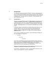
1 Introduction
1.1 Background . . . . . . . . . .
1.2 Problem description . . . . . .
1.3 Purpose and Goal . . . . . . .
1.4 Limitations and Delimitations
1.5 Related work . . . . . . . . .
.
.
.
.
.
.
.
.
.
.
.
.
.
.
.
.
.
.
.
.
.
.
.
.
.
.
.
.
.
.
.
.
.
.
.
.
.
.
.
.
.
.
.
.
.
.
.
.
.
.
.
.
.
.
.
.
.
.
.
.
1
1
2
3
4
4
2 Theory
2.1 Software Testing . . . . . . . . . . . . . .
2.1.1 Test methods . . . . . . . . . . . .
2.1.2 Types of test . . . . . . . . . . . .
2.2 Data Interchange Formats . . . . . . . . .
2.2.1 XML . . . . . . . . . . . . . . . . .
2.2.2 Bencode . . . . . . . . . . . . . . .
2.2.3 JavaScript Object Notation (JSON)
2.3 TEATIME . . . . . . . . . . . . . . . . . .
2.3.1 TIME . . . . . . . . . . . . . . . .
2.3.2 TEA . . . . . . . . . . . . . . . . .
2.4 Network Communication . . . . . . . . . .
2.4.1 TCP/IP . . . . . . . . . . . . . . .
.
.
.
.
.
.
.
.
.
.
.
.
.
.
.
.
.
.
.
.
.
.
.
.
.
.
.
.
.
.
.
.
.
.
.
.
.
.
.
.
.
.
.
.
.
.
.
.
.
.
.
.
.
.
.
.
.
.
.
.
.
.
.
.
.
.
.
.
.
.
.
.
.
.
.
.
.
.
.
.
.
.
.
.
.
.
.
.
.
.
.
.
.
.
.
.
.
.
.
.
.
.
.
.
.
.
.
.
.
.
.
.
.
.
.
.
.
.
.
.
.
.
.
.
.
.
.
.
.
.
.
.
5
5
5
9
9
9
9
10
11
12
12
12
12
. . . . . . . . . .
. . . . . . . . . .
Tools Platform)
. . . . . . . . . .
13
14
14
15
15
3 Market Analysis
3.1 Frameworks . . . . .
3.1.1 S.T.A.F. . . .
3.1.2 Eclipse TPTP
3.2 Test Environments .
.
.
.
.
.
.
.
.
.
.
.
.
.
.
.
.
.
.
.
.
.
.
.
.
.
.
.
.
.
.
. . . . . . . . . . . . .
. . . . . . . . . . . . .
(Test and Performance
. . . . . . . . . . . . .
iii
3.3
3.2.1 IBM Rational Functional Tester . . . . . . . . . . . . . 15
Result of analysis . . . . . . . . . . . . . . . . . . . . . . . . . 16
4 Method
18
4.1 Development process . . . . . . . . . . . . . . . . . . . . . . . 18
4.2 Requirements . . . . . . . . . . . . . . . . . . . . . . . . . . . 19
5 Design & Implementation
5.1 Systems description . . . . . . . .
5.2 SUT configuration . . . . . . . .
5.3 TEXAS Daemon . . . . . . . . .
5.3.1 Test file structure . . . . .
5.3.2 Configuration files . . . .
5.3.3 Sub Test Plug-in system .
5.3.4 Logging . . . . . . . . . .
5.3.5 TEXAS C# Wrapper . . .
5.4 TEXAS Manager . . . . . . . . .
5.4.1 GUI . . . . . . . . . . . .
5.4.2 Event Manager . . . . . .
5.4.3 Network Core . . . . . . .
5.4.4 Non-GUI implementation
5.5 Communication . . . . . . . . . .
5.5.1 JSON in TEXAS . . . . .
5.5.2 Message Events . . . . . .
.
.
.
.
.
.
.
.
.
.
.
.
.
.
.
.
.
.
.
.
.
.
.
.
.
.
.
.
.
.
.
.
.
.
.
.
.
.
.
.
.
.
.
.
.
.
.
.
.
.
.
.
.
.
.
.
.
.
.
.
.
.
.
.
.
.
.
.
.
.
.
.
.
.
.
.
.
.
.
.
.
.
.
.
.
.
.
.
.
.
.
.
.
.
.
.
.
.
.
.
.
.
.
.
.
.
.
.
.
.
.
.
.
.
.
.
.
.
.
.
.
.
.
.
.
.
.
.
.
.
.
.
.
.
.
.
.
.
.
.
.
.
.
.
.
.
.
.
.
.
.
.
.
.
.
.
.
.
.
.
.
.
.
.
.
.
.
.
.
.
.
.
.
.
.
.
.
.
.
.
.
.
.
.
.
.
.
.
.
.
.
.
.
.
.
.
.
.
.
.
.
.
.
.
.
.
.
.
.
.
.
.
.
.
.
.
.
.
.
.
.
.
.
.
.
.
.
.
.
.
.
.
.
.
.
.
.
.
.
.
.
.
.
.
.
.
.
.
.
.
.
.
.
.
.
.
21
21
22
23
24
25
26
30
30
31
31
33
33
34
35
35
36
6 Discussion
38
6.1 Conclusion . . . . . . . . . . . . . . . . . . . . . . . . . . . . . 38
6.2 Future work . . . . . . . . . . . . . . . . . . . . . . . . . . . . 39
Glossary
45
Appendix:
7 TEXAS User Manual
46
Appendix:
8 TEXAS Plug-in Development Guide
82
Appendix:
9 TEACUP Protocol
101
List of Figures
1.1
1.2
Ericsson F3507g Module [1]. . . . . . . . . . . . . . . . . . . .
Relations of Ericsson hardware and software. . . . . . . . . . .
2
2
2.1
"Goodness" of test case. [9] . . . . . . . . . . . . . . . . . . . .
8
5.1
5.2
5.3
5.4
5.5
5.6
5.7
5.8
System overview . . . . . . . . . . .
TEXAS Daemon overview. . . . . . .
Test structure relationship. . . . . . .
Plug-in system overview. . . . . . . .
TEXAS Manager overview. . . . . .
TEXAS Manager screenshot. . . . . .
Shows the basic concept for the core.
Data conversion in TEXAS . . . . .
v
.
.
.
.
.
.
.
.
.
.
.
.
.
.
.
.
.
.
.
.
.
.
.
.
.
.
.
.
.
.
.
.
.
.
.
.
.
.
.
.
.
.
.
.
.
.
.
.
.
.
.
.
.
.
.
.
.
.
.
.
.
.
.
.
.
.
.
.
.
.
.
.
.
.
.
.
.
.
.
.
.
.
.
.
.
.
.
.
.
.
.
.
.
.
.
.
.
.
.
.
.
.
.
.
.
.
.
.
.
.
.
.
21
23
24
28
31
32
34
36
List of Tables
5.1
5.2
5.3
Test entity attributes . . . . . . . . . . . . . . . . . . . . . . . 25
Plug-in attributes . . . . . . . . . . . . . . . . . . . . . . . . . 29
Result structure . . . . . . . . . . . . . . . . . . . . . . . . . . 29
vi
1
INTRODUCTION
This chapter intends to familiarize the reader with the background of this
master thesis. Furthermore it will describe the objectives and goal for the
work.
1.1
Background
The market for Internet access via 3G technologies has increased rapidly
during recent years. Starting in 2007, Ericsson Mobile Broadband Modules (Ericsson MBM), has expanded massively up until today. They are
developing a family of mobile broadband modems with HSPA, WCDMA,
EDGE/GPRS capabilities in various configurations [1]. Opposed to other
popular 3G modems, connected to the computer as external USB dongles,
the Ericsson modules have a mini PCI interface, suited to be fitted inside
notebooks, netbooks and MIDs (Mobile Internet Device). Ericsson targets
the notebook vendors directly, who integrates the module and the software
into their notebooks.
The bundle delivered to notebook vendors consists of:
• Module hardware
• Firmware software
• Device drivers (Windows and Linux)
• Connection Manager software (Wireless Manager, Windows only)
1
1.2. PROBLEM DESCRIPTION
CHAPTER 1. INTRODUCTION
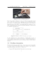
Figure 1.1: Ericsson F3507g Module [1].
Before the product is delivered to notebook vendors it is put under several
tests to make sure the module is compliant to various standards and that
the software is of satisfying quality. The MBM Integration and Verification
Functional team is responsible of performing functional verification for instance verifying that device drivers load properly and that a connection can
be established and much more.
Figure 1.2: Relations of Ericsson hardware and software.
So, the verification is not solely dedicated to verifying that one piece of
software is functioning as intended. It is critical to ensure that the interaction
between firmware, drivers and connection manager software is functioning as
intended.
1.2
Problem description
The functional testing is up until today to a large extent carried out manually
be a group of testers. The current work-flow for a member of the verification
team when verifying a new release of software is to:
• Prepare SUT (System Under Test) with correct test setup
2
1.3. PURPOSE AND GOAL
CHAPTER 1. INTRODUCTION
• Fetch test specification for the current product
• Step-by-step follow a test instruction list.
• Note if a test is pass/fail.
• If fail, file trouble report
The flow above is normally described as scripted testing [3]. As a consequence of an increasing number of customers, releases and supported platforms the workload of the functional verification team has become too large.
It has become untenable to continue to perform all functional verification
tests manually, both from a cost perspective and a time perspective.
It has been identified that the current test flow can be improved in several
areas. An internal study proposes that as much as 58% of the manual tests
are suitable for automation [11]. Overall, the test flow is in need for better
handling of test specifications and result storing.
1.3
Purpose and Goal
The objective of this thesis is to propose and implement an automated test
environment that solves the above problems. The expected outcome is to
• Reduce manual testing
• Increase test coverage
• Provide a better overview of test results
• As a consequence of the above, release products of higher quality
In parallel with this master thesis, another master thesis project, TEA-TIME
[5], is developing an inventory and tracking database to keep track of test
equipment to attend to the above problems at a higher level. It is a wish from
Ericsson to be able to connect these systems to be able to book and schedule
test execution from one place. With this proposal, TEA-TIME would act
as a higher-level test coordination system, where as the result of this master
thesis would be the test execution engine performing the actual tests. This
implies that a way of communicating between those two systems will have to
be agreed on.
3
1.4. LIMITATIONS AND DELIMITATIONS
CHAPTER 1. INTRODUCTION
1.4
Limitations and Delimitations
The current functional testing also involves verifying correct behavior of a
GUI-based connection manager software. Due to the problems connected to
verifying the correctness of graphical elements [3], this will be outside the
scope of this master thesis.
The platforms supported will only be Microsoft Windows XP, Microsoft Windows Vista and Ubuntu Linux 8.10 but with a possibility to adapt to new
platforms.
The aim of this master thesis will be to implement a framework which makes
it possible to execute functional tests in an automatic manner, but implementing and verifying individual test cases will be outside the scope of this
project.
1.5
Related work
Prior to this master thesis work, a tool for Windows called PCSWTestSuite
has been developed internally at Ericsson MBM. The basic purpose of this
tool is to address some of the issues described above. It has the possibility
to create Test Suites which defines a sub-set of Test Cases. Each Test Case
is built with Sub Tests, where a Sub Test performs a basic functionality,
such as verifying internet connectivity or verifying the presence of loaded
drivers in the system. Although proven to be quite useful, it has not been
fully developed. Written in C# .NET it is only compatible with Microsoft
Windows.
In a more general view, a lot of research has been done in the area of automated testing. Mark Fester and Dorothy Graham discuss general ways of
implementing and utilizing software testing [9]. Others propose that almost
all test can be automated, such as M.M. Siteur MBA in his book Automate
Your Testing [10]. A master thesis by Johansson and Wallinder covers the
work of implementing a testing framework for testing telecom platforms [12].
However, most published research covers the art of testing software as a
stand-alone component. In the MBM domain, it needs to be verified that
the interaction between many components is functional. Both hardware and
software aspects needs to be considered, which is why it is important to study
how a more general test tool can be beneficial.
4
2
THEORY
This chapter describes some terms and technologies that were used in the
project, which will give the reader background information on different testing theories that are relevant for this thesis.
2.1
Software Testing
Software testing is the process of executing a program or a system with the
intent of finding defects and is often used to determine the quality of the
software. Historically, testing was carried out by the programmer after the
development phase. As the complexity of software has increased rapidly,
software testing as evolved to its own separate profession. Today, software
testing is continuously carried out and has become an integrated part of the
development process.
Testing can be divided into two major concepts, black-box testing and white
box testing [3]. In black box testing, the testing is carried out without
knowledge of the internal workings of the test subject. Based on input, the
output is analyzed for correctness. This type of testing is usually applied to
test functional requirements.
White box testing, also known as glass box testing, is the opposite of black
box testing. The structure and flow of the software is visible to the tester.
The test cases are derived from the program structure.
2.1.1
Test methods
There are two ways of testing software - manual or automated. Refer to
below sections for brief explanations of the terms.
5
2.1. SOFTWARE TESTING
CHAPTER 2. THEORY
Manual testing
In manual testing a tester takes on the role of an intended end user of the
software under test. Either the tester uses scripted testing or has a more
relaxed approach and utilizes exploratory testing. In both cases, the manual
tester is responsible of setting up the test environment before testing.
In scripted testing, the tester follows a pre-made test plan. The test plan
consists of a set of test cases. The tester perform each test described and
marks the test case as pass of fail depending on the outcome.
Exploratory testing is a form of manual testing where the tester does not
follow a test plan, or very high level descriptions. It is utilized to think outside
the box and discover bugs that are not generally catched in the scripted test
plan. The tester explores the software in his own way to discover new defects
not generally covered by scripted testing. The success of this type of testing is
highly dependent on the skills of the tester and his knowledge of the software.
This type of testing has always been applied in some kind of way, but the
term was coined by Cem Kane [3] in 1983 and he has contributed to making
it more scientific.
Automated testing
The other side of the coin is automated testing. In this case, software is used
to control the execution of test cases. An action is performed automatically
and the outcome is compared to the expected result and the success is determined by this. The testing is generally carried out by some sort of testing
tool or testing framework, some of which are described in section 3.
Benefits
It is easy to understand that automating testing has several benefits. Some
of them are:
• Run more tests more often
With an automated environment it is most likely possible to run the
same tests in less time compared to manual testing. Hence, it is possible
to run the same tests over and over again with little human interaction.
This leads to greater confidence in the system.
• Run tests (close to) impossible for a human
Some testing would be very hard for a human tester to perform. Those
6
2.1. SOFTWARE TESTING
CHAPTER 2. THEORY
include things such as stress-testing a system, long time tests with
repetitive tasks to ensure long time stability.
• Utilize resources more efficiently
By removing tedious and boring tasks from the manual testers work
tasks, those resources can be used to improve test cases or debug other
faults found and perform exploratory testing instead.
• Reuse of tests
If the test cases implemented are carefully considered, the chance that
they can be reused without to much effort is great. The is a highly
desirable as many projects that are of the same character tends to run
in parallel or overlap each other.
So, the main reason for automating test is of course to save money and time,
and to increase the test coverage.
Test automation is not always suitable
A common mistake is however to assume that test automation will solve all
testing problems. It will not [3]. It is important to understand when to apply
automation of test cases. Some tests are impossible to automate, and some
are not preferable.
• Tests that are run rarely is probably to expensive to automate compared to the benefits.
• Some tests are easily verified by a human, but requires great efforts to
be verified by a computer. For instance, GUI verification can be placed
into this category. To verify that the look and feel is correct and that
correct graphics is loaded is one of those.
• Tests that require physical interaction. To relate to the domain of
MBM testing, such things would be to change the HW module, remove
the battery, remove the AC adapter and so forth.
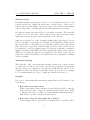
As touched upon above, there is an initial high cost of automating a test
case. An engineer has to put time an effort into developing and testing the
test case. However, if the test case is run continuously the cost associated
with the test case will decrease by time. The relationships are illustrated in
below figure by Mark Fewster and Dorothy Graham [9]. It also describes the
"goodness" of a test case. It also shows that a test case is the most effective
7
2.1. SOFTWARE TESTING
CHAPTER 2. THEORY
of finding faults when introduced. Over time, the defects covered by the test
case are corrected and the test is unlikely to find more defects. It is still a
good regression check, however.
Figure 2.1: "Goodness" of test case. [9]
Even though an automated test case passes without finding any defects,
it does not imply that there exists no faults. If test cases are not tested
properly, it may not function as intended hence causing the tester to believe
the software tested is flawless. But how can a test case be tested? Should
the test tool be tested by another automated test tool? It is easy to see that
this is not manageable. The best approach is to review the testing code and
simulate failures to make sure they are catched.
Flow of automated test development
The process of automating tests does not only involve writing good test cases.
Equally important is:
1. Test planning phase
2. Test case design
3. Test execution
4. Result handling
For this master thesis work, all those topics will be taken into consideration.
It is important that results, logging and test case scripts are made available
in formats that are structured and interchangeable to fit with other tools in
8
2.2. DATA INTERCHANGE FORMATS
CHAPTER 2. THEORY
the organization.
2.1.2
Types of test
Acceptance testing
Acceptance testing can have many meanings depending on the stake holders
involved. In the Ericsson MBM domain it means a small scope test performed
after a new software build before accepting to perform a full scope test.
Regression testing
Regression testing is the term used for testing software to make sure old
features is still working and that no new faults has been introduced due to
code changes. When a bug is fixed it can cause other parts of the software to
behave differently. It is important to run these test before releasing software
to ensure high quality.
2.2
Data Interchange Formats
As a preparation for choosing data formats used internally and for communcations protocols, some formats were inspected.
2.2.1
XML
XML (Extensible Markup Language) [17], is a widespread general-purpose
data-interchange format derived from the standard SGML (ISO 8879). It is
promoted by the W3C (World Wide Web Consortium). It is very verbose
text based format, which makes it human readable. Furthermore, many
languages have built-in support for parsing and serialization of XML.
2.2.2
Bencode
Bencode is a text-based encoding used by the peer-to-peer protocol Bittorrent
[18]. It is very lightweight, and because of the fact that it is not binary it
is often used for cross-platform applications where things such endianness
could be a problem. It is very flexible, but is not yet standardized by any
organization.
9
2.2. DATA INTERCHANGE FORMATS
2.2.3
CHAPTER 2. THEORY
JavaScript Object Notation (JSON)
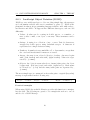
JSON is a very widely used protocol for encoding simple data, the messages
are both human readable and easy for machines to parse [7]. JSON is implemented in almost 40 programming languages which comes with ready to
use libraries and API’s. It supports five different data types, each encoded
differently:
• Values: A value can be a string in double quotes, or a number, or
true or false or null, or an object or an array. These structures can be
nested.
• Strings: A string is a collection of zero or more Unicode characters,
wrapped in double quotes, using backslash escapes. A character is
represented as a single character string.
• Numbers: A number is very much like a C or Java number, except that
the octal and hexadecimal formats are not used.
• Arrays: An array is an ordered collection of values. An array begins
with [ (left bracket) and ends with ] (right bracket). Values are separated by , (comma).
• Objects: An object is an unordered set of name/value pairs. An object
begins with (left brace) and ends with (right brace). Each name
is followed by : (colon) and the name/value pairs are separated by ,
(comma).
The most simple type is constructed as key-value pairs. a typical (key,value)
message is represented in the following way:
{ " Key1 " , " Value1 " , " Key2 " , " Value2 " , . . . , "KeyN" , " ValueN " }
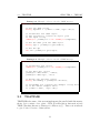
Practical examples
When using JSON, the available libraries provides rich functions to manipulate the data. The following two pseudo code examples shows how to encode
and decode a JSON Message.
10
2.3. TEATIME
CHAPTER 2. THEORY
Listing 2.1: Example of how to decode a JSON message
public void decodeExample () {
// Set raw JSON string
String inputStr = " { " name " : " John " ," age " : " 25 " } " ;
// Instanciate new JSON object
// The constructor creates an object from
// the input string .
JSONObject jsonObject = new JSONObject ( inputStr );
// Get the name from the JSON object
String type = jsonObject . get ( " name " );
// Get the age
Int id = jsonObject . get ( " age " );
}
Listing 2.2: Example of how to encode a JSON message
public void encodeExample () {
// Instanciate new object
JSONObject jsonObject = new JSONObject ( inputStr );
// Put data into object
jsonObject . add ( " name " , " John " );
jsonObject . add ( " age " , " 25 " );
// Encode into message string .
String encodedMsg = jsonObject . encode ();
// encodedMsg now contains the example string used
// in the decode example above :
// {" name ":" John " , " age ":"25"}
}
2.3
TEATIME
TEATIME is the name of the system implemented in parallel with this master
thesis. It is consists of two parts - TEA (Test Execution Automation) and
TIME (Tracking Inventory Manager for Ericsson) [5]. This section intends
to give a brief overview of this system.
11
2.4. NETWORK COMMUNICATION
2.3.1
CHAPTER 2. THEORY
TIME
TIME is a system to keep track of test assets within the Ericsson MBM unit.
These includes test computers, module samples and more. The main parts
is the underlying database, TEATIMEDB, and its web-based user interface.
It also features a physical check-in station equipped with a bar code scanner
to easily register assets.
The part relevant for this master thesis is the built-in capabilities of scheduling of automated tests. After booking a test computer, SUT, it will be possible to choose a pre-defined test suite to queue for execution on the selected
computer. The information about scheduled tests is stored in TEATIMEDB.
2.3.2
TEA
The TEA part, Test Execution Automation, is responsible of distributing
the scheduled test jobs in TEATIMEDB, booked by TIME. This is realized
by an application called TEA-Coordinator. It continuously monitors the
TEATIMEDB for upcoming scheduled test bookings. When found it will
interact with a test executor found on the client to start the test execution.
The test executor will be the result of this master thesis. Other responsibilities includes gathering information about the ongoing test, and store the
results in the TEATIMEDB. When test execution is complete, it will inform
the user of the result by SMS or e-mail.
2.4
2.4.1
Network Communication
TCP/IP
TCP/IP is a well-known communication protocol used in many applications.
As the name tells, it is seperated into two parts, TCP which is short for
Transmission Control Protocol and IP, for Internet Protocol.
1. TCP is a connection-oriented, reliable transport-layer. The main task
for TCP is to handle package flow between different systems.
2. IP on the other hand handles the routing of packages.
Together they form a reliable (no packet loss) and robust communication
protocol, used for instance by the Internet and many other network based
applications.
12
3
MARKET ANALYSIS
Prior to the actual work in the master thesis a market analysis was carried
out to gain knowledge regarding existing testing tools and frameworks. This
section will describe different views on a number of existing frameworks and
an analysis on how well suited they are for the purpose of this masters thesis.
Tools for test automation are not a new area, there are a lot of tools and
frameworks available. Therefore, it is wise to take a look at some of the
existing tools on the market.
A thorough analysis of such tools gives great overview of how a system may
look like and reduces the chance of inventing the wheel again. Because, this
type of application will always inevitable lead to a point were a decision
has to be made - either an own developed application is the best way or an
already existing tool is the best alternative.
The described frameworks/tools has been chosen because they are interesting
in their own way. The first framework describes an open source application
which is quite generic and resource efficient. Second up is a framework,
TPTP - which is a little bit more resource demanding and have a large use
base. Lastly, an analyze of a complete test environment is provided. They
all originates from IBM, but there exists of course other test environments
as well.
At the end, a result analysis is carried out to describe how well the different
applications would suit in a project like this.
13
3.1. FRAMEWORKS
3.1
CHAPTER 3. MARKET ANALYSIS
Frameworks
Before reading about the different frameworks, presented below, it is important to know what a test framework is. A framework is a set of libraries,
code or tools that can be used to build up a test environment. One could
say that a framework is like a toolbox and the user is the builder who select
the tools needed for the environment.
3.1.1
S.T.A.F.
S.T.A.F stands for "Software Testing Automation Framework" and is an open
source automation framework, originally designed by IBM for internal automation testing purposes. The purpose of STAF is to aid automation and
make it easier to create and manage automated testcases and test environments.
The basic idea of STAF is to use re-useable components with different functionality to built up tests. STAF was created with a few points in mind
[2].
• Minimum machine requirements - This is both a hardware and a software statement.
• Easily useable from a variety of languages, such as Java, C/C++, Rexx,
Perl, and Tcl, or from a shell (command) prompt.
• Easily extendable - This means that it should be easy to create other
services to plug into STAF.
The services are executed by a background process called the STAF daemon.
The daemon is responsible for serving STAF requests, both receiving and
sending. When a new request is present, it is placed in an internal queue and
is executed by the daemon. STAF allows for components to be run inside of
STAF or externally (for example a JAVA routine.)
STAF operates in a peer-to-peer environment, enabling other computers to
send requests to the STAF daemon for remote network testing.
The features described above makes STAF a flexible and powerful framework,
that can be used when building an automation tool.
14
3.2. TEST ENVIRONMENTS
3.1.2
CHAPTER 3. MARKET ANALYSIS
Eclipse TPTP (Test and Performance Tools Platform)
Eclipse is an open source community initiated by IBM, now controlled by the
Eclipse Foundation in which many companies are part of. The idea is to provide a general environment for developing new tools for the Eclipse platform.
On of its sub projects is the Eclipse TPTP (Test and Performance Tools
Platform). TPTP provides an open platform with frameworks for building new multi-purpose open source developed IDE (Integrated Development
Environment).
TPTP aims to support verification and test of the product from an early stage
throughout the application life cycle. The initiators of TPTP designed the
framework with the following quote in mind: Şto build a generic, extensible,
standards-based tool platform upon which software developers can create
specialized, differentiated, and interoperable offerings for world class test
and performance tools [4].
Some of the benefits from using TPTP [4]:
1. Save time and increase stability by automating tests and running tests
more often
2. Save aggravation by finding problems in your application faster and
with less difficulty
3. Find performance bottlenecks and other metrics easily
To achieve the statements above, TPTP comes with a rich set of functionality.
The platform provides tools for testing, tracing, profiling and logging. All
available in a common infrastructure. Support for testing frameworks as
JUnit and other Eclipse environmental tools.
3.2
3.2.1
Test Environments
IBM Rational Functional Tester
Rational functional tester is a test environment that provides tools for automated testing capabilities such as functional testing, regression testing, GUI
testing and data-driven testing. Functional Tester is a product within the
Rational software platform [8].
15
3.3. RESULT OF ANALYSIS
CHAPTER 3. MARKET ANALYSIS
The tool supports various script languages and development environments.
For example, Java can be integrated using the Eclipse framework or .NET
using Microsoft Visual Studio. This means that the tool can be adjusted to
fulfill the needs of different projects and applications.
Some of the benefits from using IBM Rational Functional Tester [13]:
1. Support for manual testing
2. Support for custom coding of test scripts
3. A platform for test management
Of course, Rational Functional Tester can be integrated with other Rational
applications, making it powerful if there already exist a Rational platform in
the project [8].
3.3
Result of analysis
One of the purposes of having this analysis was to see if there are any existing
tools available that could be used in this project, either directly or partly.
Another purpose was to see how other tools are implemented and to get a
glimpse on the features available in these types of applications, which is of
great use when creating a new application.
When looking at the available tools a distinct observation is easy to see. It is
not easy to create a generic framework/tool that directly (or even partly) can
be used according to various requirements, expectations and features from
different stake holders. From the three tools analyzed, only STAF can be
considered useful for this project.
For instance, both IBM Rational Functional Tester and TPTP lacks network
support and are both quite large applications. TPTP seems to be a better
fitted with testing code (unit testing, regression etc) rather than functional
verification.
IBM Rational Functional Tester has a lot of features that could be useful for
this project, a downside however is that the tool is proprietary, costs money
and it is uncertain if any modifications can be made in a nice way for this
project.
As mentioned, STAF on the other hand, seems to be quite well fitted for this
16
3.3. RESULT OF ANALYSIS
CHAPTER 3. MARKET ANALYSIS
project. But, when analyzing a bit deeper a lot of challenges unfolds and it
becomes clear that a lot of modifications needs to be done in order to match
the requirements.
Basically, the things that this project would benefit from using STAF would
be the network support, logging and the re-useable component architecture
and the fact that the program is under maintenance from IBM.
Due to the tight time schedule and because of the sparse benefits, the thoughts
of using STAF was discarded in order to focus on the architecture of an own
developed solution.
17
4
METHOD
The success of an implementation, task or project is often closely tied to
the preparation phase. A single decision can have severe impact on the end
result and must therefore be considered thoughtfully. In this chapter some
of the steps and decisions in this masters project will be described.
According to Sommerville [14], the process of choosing a tool for an organization often starts by browsing the market for an existing suitable solution
for the problem. Sometimes, an off-the-shelf system can be used out of the
box or with with a slight modification, sometimes a complete custom system
is required.
The first month of this project was spend on analyzing the market situation vs. a custom system implementation. When the decision was made
to implement a custom system, to avoid pitfalls and issues regarding the
planning, a project plan was initated.
4.1
Development process
The process used is called spiral development, the process is iterated a number of times. The process used included these steps:
1. Planning
2. Risk analysis
3. Development plan
4. Validation
18
4.2. REQUIREMENTS
CHAPTER 4. METHOD
5. Prototype
6. Feedback
This process starts with a planning phase to revise the time plan, resource
allocation and see what features the concluding prototype will have.
The risk analysis is needed to ensure that no requirements where unrealistic
and in need of revision.
The development and validation phase aims to fulfill the result from the
planning and risk analysis phase.
The closing phase of this development process is to wrap everything into a
prototype.
After the delivery to the customer, the planning phase starts over again based
on feedback from the customer and things that were excluded in the previous
iteration.
In the developing phase of this masters project three iterations where used:
1. Prototype I
2. Prototype II
3. Final Delivery
4.2
Requirements
Prior to the implementation phase some requirements were gathered.
Functional requirements
• Possibility to create and edit test suites graphically
• Solution which is possible to control remotely, and interact with higherlevel coordination software, such as TEA-TIME.
• Tests should be able to be executed without LAN connectivity to ensure
that WWAN connection is the only connection operational.
• Use naming scheme of test suites compatible with current set-up.
19
4.2. REQUIREMENTS
CHAPTER 4. METHOD
• If possible, provide a mechanism to re-use test code from already developed PCSWTestSuite.
Non-functional requirements
• Easy interface for configuring and creating test suites
• Small footprint
• Run on Microsoft Windows XP, Microsoft Windows Vista and Ubuntu
Linux 8.10.
20
5
DESIGN & IMPLEMENTATION
This chapter will describe how TEXAS, the result of the preceding analysis,
is implemented. TEXAS is an acronym which stands for Test EXecution
Automation System. This chapter intends to give a technical overview of the
different sub components of the system.
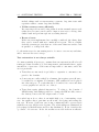
5.1
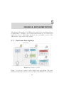
Systems description
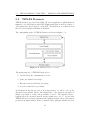
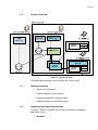
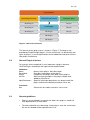
Figure 5.1: System overview
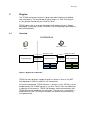
Figure 5.1 shows an overview of the complete test environment. The parts
included in this master thesis work are prefixed with TEXAS. It can interact
21
5.2. SUT CONFIGURATION
CHAPTER 5. DESIGN & IMPLEMENTATION
with TEATIME, which in short is a system used to book and schedule test
equipment for test execution. Refer to section 2.3.
TEXAS is implemented in a server-client model, where the server part, called
TEXAS Daemon, is deployed on the SUT (System Under Test) computer and
is responsible of the actual execution of test suites.
A client application, called TEXAS Manager, connects to TEXAS Daemon
and manages the setup of the test execution.
Two scenarios of usage are possible:
Stand-alone test execution TEXAS Manager and TEXAS Daemon are
both installed on a SUT without any LAN (Local Area Network) connection.
Test execution is started from TEXAS Manager locally.
Remote test execution Tests are started on a SUT connected to a internal test LAN, either from a GUI component called TEXAS Manager or from
a non-GUI TEXAS Manager controlled by the TEATIME sub-component
TEA-Coordinator.
5.2
SUT configuration
As described above, the SUT can be utilized in a LAN environment. In this
scenario, several SUTs would be connected to an internal test LAN dedicated
to be used for automated tests.
Each SUT will be configured with two partitions, one intended for the operating system and one partition for backup purposes. The backup partition
will house files such as a clean system image, and TEXAS configuration files,
and a TEXAS installation package.
The system image will be prepared with Java Run-Time and a setting to
auto-install TEXAS from the backup partition the first time it is started.
22
5.3. TEXAS DAEMON CHAPTER 5. DESIGN & IMPLEMENTATION
5.3
TEXAS Daemon
TEXAS Daemon is a Java-based TCP/IP server application, which makes it
runnable on both Windows and GNU/Linux platforms, as well as a range of
other platforms. It is deployed on the SUT, and will show as a small icon in
the tray bar in Windows/Linux, if available.
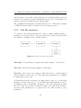
The outstanding parts of TEXAS Daemon is shown in figure 5.2.
Figure 5.2: TEXAS Daemon overview.
The main purposes of TEXAS Daemon is to:
1. Provide network communication access
2. Parse pre-defined test script
3. Execute tests described in test script
4. Provide result and log feedback
As discussed in the theory section, it is important to be able to rely on the
automated test system. Hence, the architecture of the daemon was made as
simple as possible to reduce the possibility of errors. The intention was to
separate the test execution part from the actual test code. To resolve this,
TEXAS Daemon features a parameterized plug-in system, where each plug-in
provides test functionality. When combined, these plug-ins builds test cases
23
5.3. TEXAS DAEMON CHAPTER 5. DESIGN & IMPLEMENTATION
and test suites. As a result of this design choice, test functionality is removed
from the test execution system which makes the process of debugging a lot
easier as well as developing new test functionality.
The communication interface is described in section 5.5.The inner workings
of TEXAS Daemon will be described in the following sections.
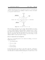
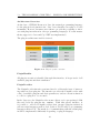
5.3.1
Test file structure
To comply to the wish from Ericsson to have a similar naming scheme to
existing tools, it was decided to categorize the test execution in an hierarchal
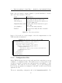
tree-manner consisting of the following entities:
Figure 5.3: Test structure relationship.
Test Suite Top structure, contains an arbitrary number of Test Cases.
Test Case Holds an arbitrary number of Sub Tests.
Sub Test This is the lowest entity. A Sub Test refers to a named plug-in
which actually executes test code. The higher levels entities are containers
for structural reasons only.
As discussed in the theory chapter, it is important to have a good test script
structure. It was decided to go for an XML-based implementation, due to
its simplicity and compatibility advantages. The test script files specifies
the flow of the test execution, namely in what order Sub Tests should be
executed, what parameters to be passed and a few other execution control
parameters.
24
5.3. TEXAS DAEMON CHAPTER 5. DESIGN & IMPLEMENTATION
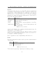
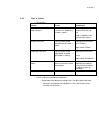
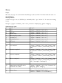
Each of the test entities contains a number of general attributes to describe
and control the execution of the test.
Name
Name
Iterations
AllowNetwork
Description
Name of the test entity.
How many iterations will be run.
Specify if a local network connection is
allowed during test.
SkipOnLastSuccessful If true and several iterations is specified, skip.
Abort if the entity run fails.
AbortOnError
Enabled
Specify if test entity should be included
in test.
Table 5.1: Test entity attributes
Refer to below table for a brief example on how the implementation of the
XML test suite is structured:
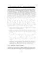
Listing 5.1: Example of the test order in XML
< TestDocument >
< TestSuite Name = " Template Test Suite " >
< Iterations > 10 </ Iterations >
< TestCase Name = " Sample Test Case " >
< SubTest PluginID = " Plugin Name " >
< InputParameters >
< Parameter Name = " Test " > Value </ Parameter >
</ InputParameters >
</ SubTest >
</ TestCase >
</ TestSuite >
</ TestDocument >
5.3.2
Configuration files
When TEXAS Daemon has received and parsed the script files it sets up
a number of configuration files. The main reason is to keep track of the
execution, in terms of current test, current iteration and number of other
parameters. These files are stored, if available, on a second backup partition. If only one partition is configured on the SUT, it will be stored in the
application folder.
The most outstanding configuration file is the lastsession.xml file. For
25
5.3. TEXAS DAEMON CHAPTER 5. DESIGN & IMPLEMENTATION
each change of the execution cycle, the current status is written to this file.
This is achieved by serializing an internal data structure to XML by using
the XStream library [16]. By writing this information to the filesystem,
it is possible to resume an ongoing test session if TEXAS Daemon, or the
operating system itself should crash. It is also useful if power tests, such as
reboot is to be performed. In this case, TEXAS Daemon will set a flag that
the shutdown is expected. The default behavior is to scan the configuration
directories for this file on start-up, and if found load and resume the last
known good state. If the shutdown was not expected, this will be written to
the log file.
The purpose of having a text file configuration file is also useful for another,
but equally important feature. The current manual test procedure includes
preparation steps where the computer is to be ghosted with a clean system
image before continuing. This means that the tester applies a pre-made file
system image with the Norton Ghost software [15]. This has to be done by
booting into a DOS-based GUI before the operating system is started. It is
desirable that this procedure is automated. The solution to this is to
1. Prepare computer with two partitions, one intended for the operating
system, and one for backup purposes.
2. Prepare second partition with a DOS-based operating system, such as
FreeDOS where ghost software can be run and system image files can
be stored.
3. Create TEXAS Daemon plug-in with the functionality to manipulate
configuration files on backup partition to select system image file.
4. Set second partition as bootable, reboot system. FreeDOS will load
and automatically start Ghost software to apply clean system image to
first partition. When done, reset first partition as bootable and reboot
computer.
5. On first run of clean system image, auto-install TEXAS Daemon from
backup partition. TEXAS Daemon will read the lastsession.xml configuration file and resume execution after the preparation steps.
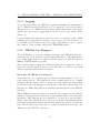
5.3.3
Sub Test Plug-in system
As described in previous section, TEXAS Daemon itself is just a testing
framework. The testing functionality is handled by plug-ins, which provides
26
5.3. TEXAS DAEMON CHAPTER 5. DESIGN & IMPLEMENTATION
sub test functionality. A sub test plug-in contributes with functionality for
a specific task.
Examples of plug-in usage:
• Install drivers
• Check drivers loaded
• Check Internet connectivity
• Put computer in different power state (sleep/hibernate/reboot)
• Measure transfer rates
• And more.
The basic idea is that each plug-in takes an arbitrary amount of input parameters and implements a predefined interface containing a run() method.
This method executes the test code and returns a test result based on the
input parameters and test code.
27
5.3. TEXAS DAEMON CHAPTER 5. DESIGN & IMPLEMENTATION
Architecture Overview
As the base of TEXAS Daemon is Java, the natural programming language
for the plug-in development is also Java. Java class files can easily be loaded
in runtime. However, measures were taken to provide the possibility to interact with plug-ins written in other programming languages. For this master
thesis, support for Java and C# .NET was implemented.
The plug-in architecture itself is 3-tiered;
Figure 5.4: Plug-in system overview.
PluginHandler
All plug-in execution is handled through this interface, it keeps track of all
available plug-ins and their attributes.
PluginProvider
The PluginProvider interface was introduced to address the issue of interacting with non-Java plug-ins. The interface provides the PluginProvider with
a list of available plug-ins and their parameters, and an execution function
to call for a plug-in to be executed.
In the Java case, the PluginProvider scans a directory for pre-packaged JAR
files and loads the plug-ins into runtime. With this generic interface, it
is possible to add new PluginProviders that executes plug-ins written in
various script languages such as Perl, Python, Tcl/Tk and/or programming
languages such as C#. The methods of communicating with the actual plugin will be implemented differently depending on plug-in language.
28
5.3. TEXAS DAEMON CHAPTER 5. DESIGN & IMPLEMENTATION
Plug-ins
The plug-ins is where the test code is defined.The plug-ins are implemented
are dependent on which PluginProvider they correspond to. However, each
plug-in needs to contain a run() function or similar that can be called for
when the test is to be executed. It also needs to be able expose what input
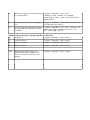
parameters are available and what the default values are. Below table 5.2
shows a list of the expected attributes.
Description
Identifies the plug-in, must be unique.
Describes the usage and purpose.
Identify version.
Provides a mean to categorize plug-ins, i.e Power Test,
Driver test
InputParameters Provides an array of expected input parameters, and
their default values.
Name
Name
Description
Version
Group
Table 5.2: Plug-in attributes
Again, how the PluginProvider communicate with the plug-ins is up to the
implementation of the PluginProvider.
As mentioned, support for C# is supported. This is provided by a separate
Windows Service called TEXAS C# Wrapper. Refer to below section 5.3.5
for description of TEXAS C# Wrapper.
Refer to appendix 8 for ways of implementing a Sub Test in code.
Result
Each plug-in run() method returns a result object, that contains information
of the outcome.
Description
Name
Message Created from within the test, message describing what
went wrong/ok inside test.
Result
Describing fail/pass
Table 5.3: Result structure
The information is passed up to higher layers for further processing.
29
5.3. TEXAS DAEMON CHAPTER 5. DESIGN & IMPLEMENTATION
5.3.4
Logging
To provide traceability two different logging mechanisms are implemented,
one for TEXAS Daemon itself and one log connected to the test execution.
The program log for TEXAS Daemon uses a third-party library called log4j,
which is an open-source logging framework developed by the Apache Foundation [6].
Logs from inside the plug-ins are saved are saved to a separate log file, which
contains only logging that are related to the test cases. It was decided to go
for an XML based format for the test logging. This makes it easy to export
the results to other software, such as the TEATIME system.
5.3.5
TEXAS C# Wrapper
The C# Wrapper is a service running along-side with TEXAS Daemon to
enable the use of C# Plug-ins. Another important aspect of the implementation of this application was to support the the legacy code (Sub Tests) from
MBM’s PCSWTestSuite program.
Since C# has superior support for Windows interaction compared to Java, it
is in some cases necessary to have a service like this to be able to do certain
Windows specific tasks in an easy matter.
Basic flow of TEXAS C# Wrapper
As described in 5.3.3, a plug-in provider has been implemented to carry out
tests written in C#. This plug-in provider contains methods for communicating with the service and to convert logs, test results and plug-in lists
received from the C# Wrapper to the Daemon. The data sent from the C#
Wrapper is a XML-string that is de-serialized and interpreted by the TEXAS
Daemon.
When TEXAS Daemon is started, it asks the C# wrapper for its available
plug-ins. The plug-in list is then sent on the channel and stored at the plugin handler. The plug-ins are now available to be used in a test execution.
When a Sub Test written in C# is about to be started, the plug-in handler
fetches the plug-in information and tells the plug-in provider to execute the
test. This works in the same way as a sub test written in Java, the only
difference is the TCP/IP connection.
30
5.4. TEXAS MANAGERCHAPTER 5. DESIGN & IMPLEMENTATION
5.4
TEXAS Manager
TEXAS Manager is a tool designed to manage the test execution by communicating with TEXAS Daemon.
It has two purposes:
1. Create and manage test suite
2. Start and monitor execution, analyze results
The design of the manager is divided into three main blocks, the GUI block,
the event manager block and the network core part.
Figure 5.5: TEXAS Manager overview.
5.4.1
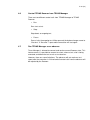
GUI
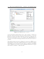
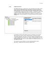
The GUI, shown in figure 5.6, features a multi-tab interface to be able to
manage several TEXAS Daemon connections. Each tab presents a workspace
where the user can create and modify test suites by simple drag-n-drop techniques. The Sub Test plug-ins available on the host system is listed in a
list box. Once a test suite is created properties of each test entity can be
set individually, and input parameters to Sub Tests can be set through the
GUI. When the user is satisfied with the structure of the Test Suite, the
test can be sent to TEXAS Daemon for execution. TEXAS Manager will
serialize the test structure to XML and send it. TEXAS Manager receives
updates continuously of the test process. To conform to the requirement
that it should be able to execute tests with no LAN activated, the user can
specify whether or not TEXAS Daemon should send status updates. When
31
5.4. TEXAS MANAGERCHAPTER 5. DESIGN & IMPLEMENTATION
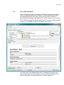
Figure 5.6: TEXAS Manager screenshot.
a test is in execution, the user has two more control options to consider; stop
and pause. If the test is stopped, the test execution is deemed to be aborted.
If the test is paused, the daemon will wait for the user to resume the test.
Both the stop and pause action is only available if the TEXAS Manager is
connected to the daemon and triggers when the next sub test is about to be
executed.
The result from the test session is displayed to the user in a HTML report,
visible when the daemon has confirmed that the test execution has stopped.
The HTML report is generated from the result log, written by the TEXAS
daemon during the test execution and is dynamically divided into new pages
if the result log contains too many sub tests.
32
5.4. TEXAS MANAGERCHAPTER 5. DESIGN & IMPLEMENTATION
5.4.2
Event Manager
The event manager serves as the bridge between the GUI and the Network
Core. The role of the event manager is to receive events from the GUI and
the Core and take action depending on which type of event that was received.
A typical event sent from the GUI through the event manager is when there
is some sort of user interaction, for example, the run button is pressed. When
this event is triggered, several events will be sent down to the network core
and forwarded to the daemon to start the test execution.
On the other hand, when something has been received from the network core,
there are several types of events sent from the event manager to the GUI,
for example, the plug-in list, status updates from the execution and other
events that the TEXAS daemon broadcasts on the network.
A big advantage of this event handler is that it can easily be tailored to fit
another purpose than a GUI application. Since, the designer can decide on
which events to subscribe to from the network core and built a new application based on these events.
5.4.3
Network Core
The network core in TEXAS Manager handles all the methods and functionality regarding the network communication. The purpose of this part is
to send and receive data on the network connection between the manager
and TEXAS Daemon. The communication to and from the event manager
is event driven, which means that the core sends up an event to the event
manager when something has been received on the network connection. Of
course, the network core also receives events from the event manager.
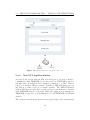
The core consists of three major layers:
1. Socket layer - Is responsible to set up or maintain an active socket
connection. Sends data on the socket, receives data, connects to clients
and listens for clients to connect.
2. Message layer - In this layer, the received data (or the data which is
about to be send) is considered and manipulated depending on the
direction of the data (receive/send)
3. Event layer - The last layer in the core handles sends events based on
the event from the message layer or the layer above (event manager).
33
5.4. TEXAS MANAGERCHAPTER 5. DESIGN & IMPLEMENTATION
Figure 5.7: Shows the basic concept for the core.
5.4.4
Non-GUI implementation
A scaled down version without GUI was developed to provide a mean to
communicate with TEATIME. As described in 2.3, TEATIME is used to
schedule tests on dedicated test computers connected to a LAN. When a
test is to be started, TEA-Coordinator launches a TEXAS Manager process
and tells it to start a test on a certain computer. The TEXAS Manager
without GUI uses the network core and a tailored event manager to interact
with TEATIME instead of the GUI. When the application is launched by
TEATIME, a network core is instantiated for both TEATIME and TEXAS
daemon.
The events received from the daemon are propagated up to the event manager
34
5.5. COMMUNICATIONCHAPTER 5. DESIGN & IMPLEMENTATION
and then forwarded to TEATIME if that message is of interest to TEATIME
(based on the agreement in the communication protocol described in appendix 9). If the event is of no use for TEATIME (i.e events that the GUI
is interested in), the event is simply discarded. Refer to appendix 7 for a
complete users guide.
5.5
Communication
As mentioned before, all communication between the different parts in the
TEXAS system is made possible through the TCP/IP protocol. The decision
to go with TCP/IP came natural in order to support remote execution of
tests and also because it is a well-used, easy to implement and a reliable
protocol.
A number of message formats were investigated before deciding which format
that would work well for the data transmission. For example; Bencode, XMLRPC and Java Object Notation (JSON) were analyzed.
Together with the TEATIME project, it was decided that JSON was best
suited.
5.5.1
JSON in TEXAS
The protocol used for communication between the different parts of the system make use of the simple but powerful protocol of JSON.
One of the main reason for choosing JSON to serve as communication protocol was because of the fact that it is widely adopted and suites well for
network communication. Another reason was that the system needed an easy
protocol that allowed for interaction with other applications in a non-complex
way.
In TEXAS, all communication between TEXAS Daemon, TEXAS Manager
and TEXAS C# Wrapper is done by JSON interchangeable messages. For
example, the TEXAS manager without GUI uses JSON to communicate with
the TEATIME system. The message protocol used in TEXAS is the same
as in TEATIME but with some extensions.
The message syntax used in TEXAS is represented in the simplest way, using
(key,value) pairs. As mentioned, JSON can be compiled into more advanced
messages representing arrays and complete objects. However, in TEXAS,
35
5.5. COMMUNICATIONCHAPTER 5. DESIGN & IMPLEMENTATION
there is no need for such advance message syntax.
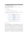
Figure 5.8: Data conversion in TEXAS
The data flow is shown in the figure above, the incoming data from the
network layer is decoded into a JSON object. The JSON object then holds
the data in a dictionary data structure.
When sending a message to the network layer, the JSON object is converted
to a string. The encoding procedure is similar to the decoding.
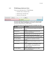
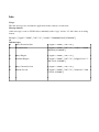
The protocol make use of three message classes:
1. Control messages (CONTROL) Used to control Texas Daemon, for
example: Start, Stop, Pause a test session.
2. Status messages (STATUS) Used to update the GUI with information
regarding the current test execution.
3. Info messages(INFO) Used to set and get information.
5.5.2
Message Events
In TEXAS Daemon there is a class responsible for the messages, the MessageHandler. It contains methods for decoding all incoming messages sent
to the network layer, also methods for sending encoded data is included in
this class.
When TEXAS Daemon is executing a test, the executor thread walks through
different stages depending on the current item. All test entities (TestSuite,
TestCase and SubTest) have their own notification event tied to them. The
notification event is the way TEXAS Daemon notifies the listeners on the
network about the current execution.
For example, when a test starts the first test entity the executor thread will
run into is a TestSuite, it will then notify the listeners that the Test Suite will
start and when the test is over an event will be sent to notify all listeners.
This works in the same way for Test Cases, Sub Tests - notification events is
36
5.5. COMMUNICATIONCHAPTER 5. DESIGN & IMPLEMENTATION
sent before and after each test instance.
37
6
DISCUSSION
6.1
Conclusion
The objective of this master thesis was to investigate and choose a test automation tool to aid the functional testing performed at Ericsson Mobile
Broadband Modules. One of the key decisions made for the thesis work was
to create a solution nearly from scratch. Although some of the existing solutions were found to be very powerful, it was concluded they were not suitable
for the demands at hand. This set the course for the project, and with the
work done it can be concluded this proposal proved to be successful.
One of the key requirements was to have a platform independent solution
which would allow for future expansion to new operating systems. This was
achieved by using Java as the basis for the server execution part.
Another crucial part was flexibility. The main concept of having different
parameterized plug-ins in a tool box for use as building blocks for new test
cases, has proven to be very useful as TEXAS has been evaluated by Ericsson
employees. It also makes it manageable to extend the test functionality
without having to re-build the entire test environment. By adding support
for C# plug-ins, it is possible to re-use old test code developed internally
with minimal effort. Also, the possibility to extend TEXAS for use with
other programming and scripting languages will be beneficial.
A functional GUI to monitor and manage test suites was developed, based on
the old PCSWTestSuite software look. This makes it easy for inexperienced
testers to create and execute new test suites.
As test suites are saved in standardized XML format, the integration with
38
6.2. FUTURE WORK
CHAPTER 6. DISCUSSION
higher-level software is made possible.
Initial efforts to support interaction with TEA-TIME, created by Sternersson
and Weber [5], was carried out successfully and the integration steps set out
in the time plan was kept.
Overall, the requirements and expectations set up in the planning phase were
fulfilled.
6.2
Future work
Although the work carried out within the scope of this master thesis came
a long way, future efforts are needed before TEXAS is put into production
usage.
TEA-TIME integration More integration work with the TEA-TIME
system needs to be done. Although stand-alone testing can be performed,
the real strength lies in the ability to book and schedule tests on dedicated
computers without directly interacting with the SUTs. It is crucial to test the
stability of the interaction with TEA-TIME as well as adding new features
for configuration purposes.
Plug-in development Some conceptual basic plug-ins were developed
during the master thesis work. Further investigation and review of current test specifications is needed to identify which functionality is wanted.
Already existing sub tests developed in C# needs to be converted to the
plug-in format used for TEXAS.
Stability and debugging It is extremely important to be able to rely on
a test execution tool to be stable. If the tool keeps crashing it is hard to trust
the results from the tool, and to know when there is an error in the tool or
error in the test subject. Even though stess testing has been performed to
some degree, more work needs to be done in this area.
Windows 7 integration The test tool was to support the specified platforms in section 4.2, but as Windows 7 is about to be released, it must be
ensured that TEXAS will function also on this platform.
39
6.2. FUTURE WORK
CHAPTER 6. DISCUSSION
GUI testing More research is needed in this field, to understand if it is
possible to combine GUI testing with TEXAS.
40
6.2. FUTURE WORK
CHAPTER 6. DISCUSSION
41
Bibliography
[1] Ericsson AB, Mobile broadband module f3507g, data sheet,
http://www.ericsson.com/solutions/mobile_broadband_modules/
docs/mobile_broadband_module_datasheet_print.pdf, June 2009.
[2] David Bender, Getting started with staf v3,
http://staf.sourceforge.net/current/STAFGS.pdf, August 2006.
[3] Bret Pettichord Cem Kaner, James Bach, Lessons learned in software
testing, Wiley Computer Publishing, 2002.
[4] IBM Corporation and Intel Corporation, Building a custom test
execution environment,
http://www.eclipse.org/tptp/test/documents/tutorials/
eclipseCon2005/EclipseCon2005_Tutorial6.pdf, February 2005.
[5] Elin Weber Erik Sternersson, Supporting a transition from manual to
automated functional testing, Master’s thesis, Chalmers, 2009.
[6] Apache Foundation, log4j,
http://logging.apache.org/log4j/1.2/index.html, June 2009.
[7] JSON, Json: description & restriction map, http://www.json.org,
November 2008.
[8] Mike Kelly, Introduction to ibm rational functional tester 6.1,
http://www.michaeldkelly.com/pdfs/Introduction_to_IBM_
Rational_Functional_Tester.pdf, 0.
42
BIBLIOGRAPHY
BIBLIOGRAPHY
[9] Dorothy Graham Mark Fewster, Software test automation, ACM Press
Books, 1999.
[10] M.M. Siteur MBA, Automate your testing, Academic Service, 2005.
[11] Mark Oscarsson, Automation investigation, December 2008.
[12] Henrik Wallinder Per Johansson, A test tool framework for an
integrated test environment in the telecom domain, Master’s thesis,
Karlstad University, 2005.
[13] Carey Schwaber, Evaluating functional testing solutions, http:
//www.forrester.com/Events/Content/0,5180,-1403,00.ppt,
June 2007.
[14] Ian Sommerville, Software engineering, 8th ed., Addison-Wesley
Publishers Ltd, 2007.
[15] Symantec, Norton ghost product page,
http://www.symantec.com/sv/se/norton/ghost, June 2009.
[16] XStream Developer Team, Xstream website,
http://xstream.codehaus.org/, June 2009.
[17] W3C, Extensible markup language (xml), http://www.w3.org/XML/,
June 2009.
[18] Wikipedia, Bencode, http://en.wikipedia.org/wiki/Bencode, June
2009.
43
Glossary
EDGE
Enhanced Data rates for GSM Evolution
GPRS
GUI
General Packet Radio Services
Graphical User Interface
HSPA
High Speed Packet Access
LAN
Local Area Network
MBM
MID
Mobile Broadband Modules
Mobile Internet Device
PCI
Peripheral Component Interconnect
S.T.A.F
SUT
Software Testing Automation Framework
System Under Test
TEA
TeaTime
TEXAS
TIME
TPTP
Test Execution Automation
Inventory and tracking system
Test EXecution Automation System
Tracking Inventory Manager
Test and Performance Tools Platform
USB
Universal Serial Bus
WCDMA Wideband Code Division Multiple Access
44
Glossary
Glossary
WWAN
Wireless Wide Area Network
XML
eXtensible Markup Language
45
7
TEXAS USER MANUAL
46
A 1 (35)
TEXAS User's Manual
Abstract
This document includes manuals for how to use TEXAS Manager and TEXAS
Daemon.
A 2 (35)
1
INTRODUCTION
4
1.1
System basics
4
1.2
System Overview
5
1.3
Features overview
5
1.4
Supported host operating systems
5
2
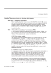
INSTALLATION
7
2.1
Installing on Windows hosts
2.1.1 Prerequisites
2.1.1.1
TEXAS Daemon
2.1.1.2
TEXAS Manager
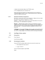
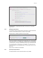
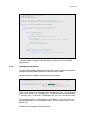
2.1.2 Performing the installation
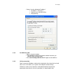
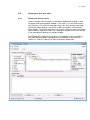
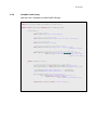
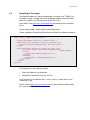
4. Specify the destination folder of the TEXAS system.
2.1.2.1
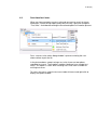
Note about the different components
7
7
7
7
7
8
8
2.2
Installing on Linux systems
2.2.1 Prerequisites
2.2.1.1
Texas Daemon
2.2.2 Performing the installation
8
8
8
8
3
9
STARTING OUT WITH TEXAS
3.1
Verify that TEXAS Daemon is running
9
3.2
Starting the graphical user interface
9
3.3
Setting up the system for remote testing
3.3.1 Windows Vista
3.3.2 Windows XP
3.3.3 On GNU/Linux XP
3.3.4 Verify connection
4
10
10
13
15
15
TEXAS MANAGER
16
4.1
Connect to TEXAS Daemon
4.1.1 Local Daemon
4.1.2 Remote Daemon
4.1.3 TEXAS Manager View
4.1.4 Multiple connections
16
16
17
18
18
4.2
Create your first test suite
4.2.1 Create your first test suite
19
19
4.3
Save/Load test items
20
4.4
Set up module information
21
A 3 (35)
4.5
Run a test suite
22
4.6
Control TEXAS Daemon from TEXAS Manager
23
4.7
Run TEXAS Manager as an observer
23
4.8
Test report generator
24
4.9
Sub test settings
4.9.1 Sub test settings
4.9.2 Basic settings
4.9.3 Global parameters
26
26
27
28
4.10
Tips ‘n’ tricks
29
4.11
TEXAS Manager Notification Fields
30
4.12
Settings
4.12.1
Report filter
31
31
4.13
Control
4.13.1
Local C# wrapper
31
31
4.14
31
5
5.1
6
Closing TEXAS Manager
TEXAS DAEMON
User interaction with TEXAS Daemon
GLOSSARY
33
33
35
A 4 (35)
1
Introduction
Test EXecution Automation System (TEXAS) is a tool for automated testing
primarily implemented for MBM to aid functional verification. With TEXAS, you
can easily set up test suites based on the provided sub tests to ease the daily
verification work. The system consists of two parts, TEXAS Manager (TM)
and TEXAS Daemon (TD).
1.1
System basics
The heart and soul of TEXAS is the TD. TEXAS Daemon is where the actual
sub tests are executed. The sub tests are integrated into the framework as
stand alone plugins. Since TD is mainly working as a backend program and
does not support a lot of user interactions, its counter program is the TEXAS
Manager. The Manager works as a front end to TD and represents it through
a GUI.
In TM, you establish a connection to a Daemon and you will receive a list of
available sub tests. Then, a test suite can be built and executed on the
Daemon. TM and TD communicate through a socket interface and TD
updates the GUI by sending status messages, which are processed and
displayed by TM.
A test session is divided into three blocks, and the following terminology will
be used throughout this document:
•
Test Suite
o Test Case
Sub Test
A test suite is the container of the test. A test suite can contain several test
cases. A test case is a building block inside the test suite making it possible to
group several sub tests into different blocks to give a nice structural
representation of the test session. As mentioned above, a sub test is the
lowest level in the session and represents the actual test.
Because of the socket based communication interface, the Daemon can be
isolated on a remote host and enables for remote testing.
The Daemon is implemented in JAVA™ to support different platforms as the
JAVA™ runtime application is platform independent.
A 5 (35)
1.2
System Overview
Figure 1: System Overview
The above figure describes the interaction with TeaTime [ref].
1.3
1.4
Features overview
•
Generic test framework
•
A great number of useful sub tests
•
Platform independent execution engine
•
Supports remote or stand alone testing
Supported host operating systems
Currently, TEXAS is available and has been verified for the following
operating systems:
•
Windows
A 6 (35)
o Windows XP (32 and 64 bit)
o Windows Vista (32 and 64 bit)
o Windows 7 RC1
•
GNU/Linux
o Ubuntu 8.04 (“Hardy heron”)
o Ubuntu 8.10 (“Intrepid Ibex”)
A 7 (35)
2
Installation
Since TEXAS can be installed on different operating systems, this manual will
cover instructions for both Windows and Linux, respectively.
2.1
Installing on Windows hosts
2.1.1
Prerequisites
2.1.1.1
TEXAS Daemon
Java™ 6 Runtime
2.1.1.2
TEXAS Manager
.NET Framework 2.0
2.1.2
Performing the installation
1. Install TEXAS on your system by double-clicking on its installer file,
TEXASSetup.exe
2. Press “I Agree” when the window has been initialized
3. Choose components to install (see 3.1.2.1) and click “Next”
A 8 (35)
4. Specify the destination folder of the TEXAS system.
5. Press Install and let the installation finish.
Please note that the installation can take some time to finish. Before the
installation program finishes, it starts TEXAS Daemon and runs some helper
scripts to set up the environment.
2.1.2.1
Note about the different components
Most often, you want to install all three components. However, here are some
descriptions of the different components’ functions.
Daemon – TEXAS Daemon: Without TD you will not be able to run any tests
on the system. TD is required for test execution.
Manager – TEXAS Manager: Without TM you will not be able to create or
modify existing Test suites and test cases. However, if you only need to run a
specific test suite file and is not interested in the graphical representation of
the test execution – it’s possible to skip the installation of TM (see 5.x.x for
more info).
C# Wrapper – Some specific Windows sub tests requires that the C# wrapper
is installed. The C# wrapper is an additional component that executes sub
tests and is a helper program for the Daemon when interacting with Windows.
2.2
Installing on Linux systems
2.2.1
Prerequisites
2.2.1.1
Texas Daemon
Java 6 Runtime edition.
2.2.2
Performing the installation
From the TEXAS installation folder (make sure you are the super user):
•
Either double-click the Install.sh
•
or type ./Install.sh
Texas will now be located in /opt/TEXAS
Done!
A 9 (35)
3
Starting out with TEXAS
This section will describe initial instructions on how to run the TEXAS system
on different operating systems. Please note that there exists no GUI for
GNU/Linux, yet. Please go to section 4.3 “Setting up the system for remote
testing” if you want to use TEXAS Manager and a Daemon running on
GNU/Linux.
3.1
Verify that TEXAS Daemon is running
TEXAS Daemon is supposed to be started from the installer. When TEXAS
Daemon is active and running, it’s located in the tray area like this:
Figure x: Texas daemon is up and running
3.2
Starting the graphical user interface
•
On windows, either double-click the desktop icon labeled “TEXAS
Manager” or browse to Program->Ericsson->TEXAS->Manager
A window like the following should come up:
A 10 (35)
3.3
Setting up the system for remote testing
This section will describe how to set up a network to make remote testing
available. Follow the instructions for the corresponding OS.
First: follow the installation guidelines in section 3 to deploy the TEXAS
system correctly on the target system.
Please note that this has to be done on both the client and the remote
system and they cannot have the same IP addresses.
3.3.1
Windows Vista
o Go to the control panel
o Go to Network and Sharing center
o Click on “Manage network connections”
o Select the network interface you want to use and right-click to
get into properties
A 11 (35)
o Highlight “Internet Protocol Version 4” and press the Properties
button
A 12 (35)
o Select “Use the following IP address”
IP Address: 192.168.1.1
Subnet mask: 255.255.255.0
Skip gateway
A 13 (35)
3.3.2
Windows XP
o Go to the control panel
o Go to Network Connections
o Click on “Manage network connections”
o Select the network interface you want to use and right-click to
get into Properties
A 14 (35)
o Highlight “Internet Protocol (TCP/IP)” and press the Properties
button
A 15 (35)
o Select “Use the following IP address”
IP Address: 192.168.1.1
Subnet mask: 255.255.255.0
Skip gateway
3.3.3
On GNU/Linux XP
o Open a terminal window
o Type ifconfig and determine which network interface you
should use(for example eth0)
o Run sudo ifconfig eth0 192.168.1.1 up to set the address.
3.3.4
Verify connection
Open a terminal (Windows: cmd) and try to ping the client from the host and
vice versa. If this works, the systems are ready for remote testing.
Otherwise, make sure all firewalls are disabled and that the physical
connection from client host is possible (i.e. check cables etc).
A 16 (35)
4
TEXAS Manager
4.1
Connect to TEXAS Daemon
As mentioned earlier, there are two ways to execute tests in TEXAS. You can
either start the test on a local running Daemon or a Daemon running in the
network on a remote system. This section will describe how to connect to
TEXAS Daemon from TEXAS Manager both remotely and locally. The last
bullet will handle multiple connections. This means that TM can connect to
several TEXAS Daemons, making it possible to control several tests on
remote computers from one client.
4.1.1
Local Daemon
Start TEXAS Manager as described in section 4.2. When the GUI has started,
press file and go to Connect Local Daemon.
After pressing “Local Daemon”, TM will initialize the manager view. See 5.1.3.
A 17 (35)
4.1.2
Remote Daemon
Start TEXAS Manager as described in section 4.2. When the GUI has
started, press file and go to Connect Remote….
A connection window will appear where you have to specify the IP address
and port (Default port is 55001) to the remote TEXAS Daemon. TM will now
initialize the manager view. See 5.1.3
A 18 (35)
4.1.3
TEXAS Manager View
When TM has connected to TEXAS Daemon, a new tab view will be created
representing the connection to TD.
The list on the left is where the available sub tests are displayed. The plugins
are displayed under certain group identifiers, to enhance the user experience.
In the middle, there is a window called “Test Suite”. This is the work space of
the current test, here you can build your test cases and suites from the sub
tests in the plugin window. This will be described in section 5.2.
4.1.4
Multiple connections
It is possible to connect to several TEXAS Daemons from TM. When a new
connection is established, a new tab is initialized that displays the current
status of that system. This enables remote testing on several computers with
a single instance of TM.
A 19 (35)
4.2
Create your first test suite
4.2.1
Create your first test suite
Choose a plugin from the plugin list and either double-click or drag ‘n’ drop
the plugin onto the workspace window (“Test Suite”). This will auto create a
tree view with a Test Suite as top node, then a test case and then the plugin
you picked. Some plugins (see section 7 about the plugins) have different
input settings. The normal work flow is to choose a sub test, add it to the work
space and then right-click->Sub Test->Settings or double-click on the sub test
in the workspace to display the settings window.
The window to the right (when a sub test is highlighted in the work space),
describes different options regarding the test execution. Please refer to
section 4.7 “Sub test settings” for more information about them.
A 20 (35)
4.3
Save/Load test items
When you have created a new test suite and you want to save it for future
encounters. Select the top node (under New session), right-click and go to
“Test Suite”. A window describing the Save/Load options will now be present.
Press save test suite and a dialog window is present to letting the user
choose where to put the file.
In the picture above, except saving a test suite, there are two options
regarding test cases. These options enables loading of user created test
cases. This option is useful when creating a test suite from a number of
existing test cases.
To save a test case, select the test case node of interest and right-click to
display the option window.
A 21 (35)
4.4
Set up module information
There are different projects, different brands and different network operators.
To ease the work for the Daemon, you as the user will be encouraged to
provide this information upon the test initialization. There are two ways of
specifying this information:
•
Select “New session” in the workspace and look in the settings
window to the right. There should be three fields named Vendor,
Project, Network. Choose one name from the drop down box in each
of these fields if you will interact with a module during the session.
•
The other way, is to press Run and fill out the information in the pop
up window that will be displayed if the information is mission. There
will be three options to choose from in this window. Abort, Skip and
Ok.
Please note that the pop up window only will appear when the
information has been provided. After that, alternative one is the only
way of changing the information.
A 22 (35)
4.5
Run a test suite
When you are happy with your test suite and want the Daemon to execute it,
just press the “Run” button and the execution will start. If you have not
specified information about the module you are testing on the pop up
described above will be present. The test suite execution will then start and
the tree nodes in the workspace will change their state from a orange
question mark to a spinning gear.
The status of the execution is updated throughout the test. When a sub test is
finished, a green icon for pass or a red icon for fail is displayed, making it
easy to follow the execution phase. A more detailed execution log is provided
in the “Progress status” view, in the tab named “Results”.
When a test suite is finished and the execution has stopped. TEXAS Daemon
sends a test report to the manager, containing useful information about the
test run. See 4.7 for more information.
A 23 (35)
4.6
Control TEXAS Daemon from TEXAS Manager
There are tree different control calls from TEXAS Manager to TEXAS
Daemon.
•
Run
Run starts a test.
•
Stop
Stop aborts an ongoing test
•
Pause
Pause, halts the ongoing test. When paused, the button changes name to
“Resume”. If “Resume” is pressed the execution will start again.
4.7
Run TEXAS Manager as an observer
Texas Manager is allowed to connect and receive current Daemon state. This
feature means it is possible to connect to a host, where a test suite is being
executed, and follow the test results as an observer.
However, there are some limitations. The observer will not receive a test
report after the execution is finished and all control calls from the observer will
be rejected by the Daemon.
A 24 (35)
4.8
Test report generator
When a test suite has been executed, an XML log file of the run test will be
sent to TEXAS Manager from the Daemon. A nicely formatted test report
including detailed prints from each sub test that has been executed, is
generated by the Manager and displayed in a HTML-viewer for easy viewing.
When TEXAS Manager has generated the report, it will automatically display
it under the “Test Report” tab in the “Progress status” panel.
As can be seen in the window above, there is a button with a green icon
located to the top left of the test report view. By clicking this button the test
report is displayed in a stand alone browser (Internet Explorer).
A 25 (35)
The reports are split up in one main page and one or more result pages. The
main page presents system information, module information, a result
summary and links to relevant result pages.
The screenshot below shows the result page of a report in a stand alone
browser. Here, each sub test is underlined and when it’s clicked, the
information about the specific sub test will be expanded in the report. If the
link is clicked when the information is visible, the sub test information will
collapse and become hidden once again.
It is possible to expand/collapse all subtests on a page through a single click
by using the links in the menus available in the top and bottom of the page.
A 26 (35)
If you want to view a report that has been previously generated, you can use
the menu choice View Report… accessed from the File menu, and locate the
HTML report main file. You could also locate and open an XML log file from a
run test created by a TEXAS Daemon with this menu choice. When doing
that, a new HTML report is generated. Both when opening an already
generated HTML report, and when generating a new one, the report will be
shown in a standalone browser (Internet Explorer).
4.9
Sub test settings
For each sub test there is a settings area in the rightmost window of TEXAS
Manager. This section will describe each field and what the purpose they
have and what impact it will bring to the test run.
There are three different setting types to consider in TEXAS Manager
4.9.1
•
Sub Test Settings
•
Basic Settings
•
Global Parameters
Sub test settings
A lot of the sub tests have one or more input parameters. For example, the
subtest “Wait”. Wait halts the execution for a specified interval. That interval
can be changed in the subtest settings. To change an input parameter, you
can either highlight and double-click on the sub test or right-click and choose
Sub Test -> Settings. When this is done, a window like the following will be
displayed:
The input box(es) inside the Parameters border is input parameters to the
subtest. The second displays a brief description on how the test is intended to
work. When the parameter values have been changed, press Save and the
window will be closed and the values stored.
A 27 (35)
4.9.2
Basic settings
This settings option applies to every test item. It can be modified for the whole
test suite, for different test cases and even for the sub tests. The basic
settings window appears to the right when a test item node is selected and
looks like this:
There are six different settings that can be modified:
•
Name – the displayed name of the test. This name can be changed.
•
Description – If you would like to describe the test item more detailed
then a description can be added in this field.
•
Iterations – how many times will this test be executed.
•
AllowNetwork – Sometimes you might want to disable the network
interface to face a certain requirement or so. If the value is true, then
the network adapter will be enabled, if false then it will be disabled.
Please note that this will disable all communication between TM
and TD
•
SkipOnLastSuccessful – If you have several iterations on a test and
you want to skip the iteration if the last result of this item was
successful, then enable this option.
•
InvertResult – If you expect an error from a test you can invert the
test result.
•
AbortOnError – If this option is set to true, the execution will abort if
this test item fails.
•
Enabled – If you have a large test suite and only want to run a few
test cases or sub tests. The daemon will skip execution of every test
item with this setting set to false.
A 28 (35)
4.9.3
Global parameters
With global parameters, a generic test suite can be built and used by several
users. The only modification that has to be done is to make sure that the
global parameters are set to a proper value. When setting a subtest setting,
instead of typing a value you can type an identifier. The identifier is then used
in a global settings window where you can assign a value to it. What will
happen is that every sub test containing this identifier as an input value, will
get the global value of the identifier as the input parameter for the specified
setting.
An example: In the test suite above, there are six wait tests. One of them
does not have a numeric value as input parameter. Instead it has been
assigned the identifier <wait_time>. This tag is a global value identifier which
can be modified from the “New session” node. As the picture above tells, the
global parameter <wait_time> has been added to the GlobalParameters list in
the rightmost window.
So, if there are several subtests in a test suite containing the same
parameters, a global parameter might be a good choice.
A 29 (35)
4.10
Tips ‘n’ tricks
•
Short keys
Action
Result
Command
Add sub test
A sub test is added to
the work space
Double-click the sub
test
Drag ‘n’ drop the sub
test with the mouse
Delete test item
The test item will be
deleted from the work
space
Highlight the test item,
press Delete
Right-click->Delete
Duplicate test item
The test item will be
duplicated, inserted
right after its sibling
Highlight the test item
Ctrl+D
Right-click Duplicate
Move
•
Move a test item in the
work space.
Highlight the node of
the test item and drag
‘n’ drop the item up
and down
Basic settings and global parameters
o Read about the different settings that can be used to do more
accurate testing and set up generic test suites that can be
used by several users.
A 30 (35)
4.11
TEXAS Manager Notification Fields
There are tree notification fields in TEXAS Manager.
•
Execution status (The green area)
•
Network status (The blue area)
•
Status bar (The red area)
These three notification fields update the user with useful information about
the current state. Network status displays if the network is up and running,
meaning a valid connection to TEXAS Daemon.
The status bar shows a lot of different information, for example it can show:
Message
Description
Received current view
Plugins received and the window was initialized
properly.
Setting up test
Initialize test, prepares for file transmission,
generation of test data etc.
Sending file
Information about the current file while it gets
transferred like speed and a byte counter.
Receiving test file
Like sending a file but now it is receiving instead.
Test was aborted
Displayed when the stop button has been
pressed.
Test is paused
Displayed when the pause button has been
pressed.
Critical failures
When the Daemon has encountered a serious
fault, for example if it can’t start the test or a
message could not be interpreted. A critical
message is received.
Test item updates
Updates regarding the different test stages,
executing, completed etc.
A 31 (35)
4.12
Settings
To view or edit the settings of TEXAS Manager, go to File -> Settings…. The
settings dialog is based on tabs and currently, the only available setting is
Report filter in the Reports tab (see 5.12.1). The Close button of the dialog
exits the dialog and does not save any changed settings. The Save button
saves changed settings and exits the dialog.
4.12.1
Report filter
The Report filter setting allows the user to specify the detail level of the
generated HTML reports. The available choices together with what they mean
are:
•
•
•
4.13
Show all subtests
All subtests of the run test session are reported. This is the default setting.
Show only passed subtests
Only the subtests of the run test session that passed are reported. This
option could be useful when you are running many tests (or iterations of a
test) where you expect a lot of fails, to filter out what is actually working as
intended.
Show only failed subtests
Only the subtests of the run test session that failed are reported. This
option could be useful when you are running many tests (or iterations of a
test) where you expect a lot of passes, to filter out what is actually not
working as intended.
Control
There is a Control menu available in TEXAS Manager. In this, you can control
some parts of the test execution environment. Currently, there is only one
submenu, namely Local C# wrapper (see 5.13.1).
4.13.1
Local C# wrapper
Some subtest plugins are Windows specific. This means that they can only be
run on Windows. To enable this, a Windows service called “TEXAS C# Test
Executor” runs in the background, executing all those subtest plugins. If you
for some reason want to control the running state of that service, you can use
this menu and through it either start, stop or restart the service.
4.14
Closing TEXAS Manager
Closing TEXAS Manager can be done in three different ways
1. Closing the tab (this actually only closes the connection to that Daemon)
2. Closing the complete window
3. Closing by navigating to File Quit
A 32 (35)
However, if there is an ongoing test at the daemon when the program or tab is
closed, please remember that the Daemon will expect you to re-connect and
gather the test result.
This means that the Daemon will be occupied and no one but you or a
user with the same IP can collect the test data and making the Daemon
available again.
A 33 (35)
5
TEXAS Daemon
5.1
User interaction with TEXAS Daemon
TEXAS Manager is the best way of interacting with TEXAS Daemon, but if
this is not possible due to operating system or other reasons, the Daemon
itself has a number of features that a user can use.
When TEXAS Daemon is up and running, there should be a TEXAS icon in
the tray bar on both Windows and Linux. To enable the Daemon menu, rightclick the tray icon and this menu will appear:
Existing menu items:
•
About
o A popup window is displayed, showing information about the
Daemon. It will display:
•
Build – The version number
Port – The listening port of the Daemon
Status – Current execution status.
Run Test Suite
o This option prompts a window where the user can specify a test
suite file. This option is useful on GNU/Linux systems where
there exists no GUI (no TM). The test suite can be created
from a Windows computer and then be loaded on a Linux
system.
•
View Report
o The user can select a .log-file and a HTML report is generated
and opened in the default web browser of the system.
A 34 (35)
•
Refresh Plugins
o If all plugins didn’t appear in the plugin list of TM, this option will
do another scan and send whatever content it finds.
•
Reset state
o If it is impossible to connect to TD for some reason, it might be a
good idea to reset the internal state to see if the issue is
solved.
•
Iteration
o If a test is running, the current iteration of the test suite is
displayed. Useful when running a test suite not using TEXAS
Manager.
•
Exit
o Closes TEXAS Daemon.
A 35 (35)
6
Glossary
Name
AT command
TD
TEXAS
TM
TeaTime
Test Item
S3
S4
Description
A command which the broadband module understands.
AT commands are used internally to control and get the
state of the module.
TEXAS Daemon: Application that executes tests. A
Daemon can be administered via its own tray menu or
from a Manager.
Test EXecution Automation System
TEXAS Manager: Application used to administer and
control one or several Daemons. Through TM you
control the execution of tests and also, you can create
and edit test suites.
Test Execution Automation and Tracking Inventory
Manager at Ericsson: consists of two parts; a test
execution part that can be used to schedule tests on
dedicated test computers, and a computer/module
searching and booking websystem.
All elements part of a test suite is considered to be a
test item. This could either be a test suite, a test case or
a subtest.
An operating system power state. Also known as Sleep.
An operating system power state. Also known as
Hibernation.
8
TEXAS PLUG-IN DEVELOPMENT GUIDE
82
B 1 (18)
TEXAS Plug-in Development
B 2 (18)
Contents
Contents ........................................................................................................ 2
1
Introduction .......................................................................................... 3
1.1
Abbreviations............................................................................ 3
2
Plug-ins................................................................................................. 4
2.1
Overview .................................................................................. 4
2.2
General Plug-in interface .......................................................... 5
2.3
General guidelines.................................................................... 5
2.4
Documentation ......................................................................... 6
3
Developing a Java plug-in ................................................................... 7
3.1
Setting up the environment ....................................................... 7
3.2
Implementation ......................................................................... 7
3.2.1
Basics....................................................................................... 7
3.2.2
Adding input parameters .......................................................... 8
3.2.3
Retrieving input parameters...................................................... 8
3.2.4
Run method and Test Result .................................................... 9
3.2.5
Logging .................................................................................... 9
3.2.6
Complete code listing ............................................................. 10
3.3
Compiling & Packaging .......................................................... 11
3.4
Deployment ............................................................................ 12
4
Developing a C# Plug-in .................................................................... 13
4.1
Setting up the environment ..................................................... 13
4.2
Implementation ....................................................................... 13
4.2.1
Basics..................................................................................... 13
4.2.2
Adding input parameters ........................................................ 14
4.2.3
Retrieving input parameters.................................................... 15
4.2.4
Run method and Test Result .................................................. 15
4.2.5
Logging .................................................................................. 15
4.2.6
Complete code listing ............................................................. 15
4.3
Compiling & Packaging .......................................................... 17
4.4
Deployment ............................................................................ 18
B 3 (18)
1
Introduction
This document will describe how to extend functionality in TEXAS (Test
Execution Automation System) used within the MBM department, by adding
plug-ins. Please refer to xxxx for a detailed overview of the implementation
and use of the system.
1.1
Abbreviations
TM
JAR
DLL
ANT
CLI
DUT
TEXAS Manager
Java ARchive
Dynamic-link Library
Another Neat Tool
Command Line Interface
Device Under Test
B 4 (18)
2
Plug-ins
The TEXAS environment features a plug-in based architecture for adding
new functionality. The terminology for these plug-ins is “Sub Test Plug-ins”,
as they provide functionality on a Sub Test level.
TEXAS comes with a set of pre-developed multi-purpose plug-ins. Before
developing a new plug-in make sure there is no existing plug-in providing the
desired functionality.
2.1
Overview
Architecture
System Under Test
Client
Default port: 55001
Ask for Sub Tests Plugins
TEXAS Manager
Execute Test Suite
Receive result + logs
TEXAS Daemon
Default port: 49999
Ask for Sub Test
Plugins
Execute Sub Test
Receive result + logs
TEXAS C# Wrapper
Plugin
Plugin
Plugin
Plugin
Plugin
Plugin
Plugin
Plugin
Figure 1: High-level architecture
TEXAS currently provides support for plug-ins written in Java or C# (.NET
2.0) deployed as JAR files and DLL files respectively.
As the core component, TEXAS Daemon, is written in Java, JAR files can be
loaded directly into TEXAS Daemon in run-time. C# DLL files are loaded into
a separate service process, TEXAS C# Wrapper, which communicates with
TEXAS Daemon to coordinate test execution. The end user is exposed to a
combined list of Sub Test Plug-ins but does not need to concern how they
are implemented.
B 5 (18)
PluginHandler
NativePluginProvider
CSharpPluginProvider
Java Plug-in
Extension point
Plug-in
Java Plug-in
C# Wrapper
Plug-in
Java Plug-in
C# Plug-in
Plug-in
C# Plug-in
C# Plug-in
Figure 2: Low-level architecture
The internals of the plug-system is shown in Figure 2. The plug-ins are
provided by PluginProvider objects. If in the future there is a demand for new
types of plug-ins, a new PluginProvider can be added that interfaces with the
new plug-in architecture.
2.2
General Plug-in interface
For a plug-in to be recognized, it must implement a plug-in interface,
ISubTestPlugin, according to the high-level description below.
Attributes:
Name
Description
Group
Version
InputParameters
Functions:
Run
2.3
Names of the plug-in. Must be unique!
Describes the purpose of the plug-in.
Categorizes the plug-in with other similar plug-ins.
What versioning number is the plug-in. Maybe autoadded by ClearCase?
Specifies what input parameters can be passed to the
plug-in and what the default parameter values are.
Execute the test code, and return a test result.
General guidelines
•
Plug-ins are not loaded in any particular order, thus plug-ins should not
have dependencies on each other
•
The Name identifier must be unique. If two plug-ins have the same name,
the one last loaded will be exposed to the user.
B 6 (18)
2.4
•
Try to make the plug-in as generic as possible.
•
If possible, implement in Java to eliminate unnecessary communication
overhead.
Documentation
Update internal document with a complete description of:
•
The purpose of the plug-in
•
Usage
•
Known limitations
•
Parameter descriptions
B 7 (18)
3
Developing a Java plug-in
This section will describe hands on step-by-step how to get started with
writing Java plug-ins. It assumes you have prior basic knowledge of Java
and Eclipse.
3.1
Setting up the environment
It is recommended that Eclipse is used for Java developing.
When Eclipse is set up, create a new project and import TexasDaemon.jar
available in CC to access the required interfaces and abstract class
specifications. This can be done by right clicking on the Project -> Properties.
In Build-path, choose “Add External JARs” and point to TexasDaemon.jar.
3.2
Implementation
3.2.1
Basics
Create a new class in the project, “JavaPlugin”, and put it in package
com.ericsson.mbm.texas.daemon.plugins.
As mentioned, the class needs to implement the ISubTestPlugin interface. It
is recommended to extend AbstractSubTestPlugin to access some helper
functions. AbstractSubTestPlugin implements ISubTestPlugin.
Also import com.ericsson.mbm.texas.daemon.testentities.*; to
access needed definitions.
Set the basic attribute settings in the constructor, such as name, description,
group and version.
To fulfil the interface we also need to implement a run() method. This
method will be called when the plug-in is executed. The semantics of this
method will be covered further on.
B 8 (18)
package com.ericsson.mbm.texas.daemon.plugins;
import com.ericsson.mbm.texas.daemon.testentities.*;
public class MyFirstJavaPlugin extends AbstractSubTestPlugin {
MyFirstJavaPlugin() {
// Name the plug-in
this.setName("My First Java Plugin");
// Describe the purpose/usage
this.setDescription("This test will do almost nothing.");
// Set the group name
this.setGroup("Dummy tests");
// Set version
this.setVersion("0.1");
}
public TestResult run() {
// TODO Auto-generated method stub
return new TestResult(true, "Test executed.");
}
}
The above code is enough to get the plug-in running, even if it would be
pretty useless.
3.2.2
Adding input parameters
It is possible to specify input parameters to the plug-in in order to control the
execution and what data to process inside the run() method.
Input parameters should be specified in the constructor:
// Add input parameter with default value
this.addInputParameter("disp_text", "Display text", "Default value");
// Add input parameters with multiple choosable values
this.addInputParameter("disp_text_option", "Display text 2",
new String[] {"Default value", "Option value #1", "Option value #2"});
The first line specifies an input parameter named “disp_text”. The descriptive
name shown to the user is “Display text”. The default value of the parameter
is “Default value”. If no value is specified by the user, this value will be used.
The second line takes a String array as value option. This means the user
will presented with a list of choosable values. The first value in the list is the
default one.
Please refer to JavaDoc for further details.
3.2.3
Retrieving input parameters
The input parameters can be retrieved inside the run() method.
B 9 (18)
// Retrieve parameters values
String parameter = this.getInputParameter("disp_text");
String parameter2 = this.getInputParameter("disp_text_option");
Note that all parameter values are strings. If you want to pass Integers or
other data types to the plug-in, do parse the string values after they have
been retrieved, for instance by using Integer.parseInt(stringval).
3.2.4
Run method and Test Result
When the input parameters have been retrieved implement your test code.
Please comment the code and follow the Ericsson Java common guidelines.
(?)
The run() method must return a TestResult data type. The TestResult
specifies the outcome of the test, if the test was successful and also provides
a custom message. The default constructor is:
TestResult(boolean successful, String message)
Example:
if (parameter.equals("a string value")) {
return new TestResult(true, "Test executed successfully.");
}
return new TestResult(false, "Test failed duo to incorrect input param");
3.2.5
Logging
AbstractSubTestPlugin provides the object logger of type TestLogger which
can be called to log events during the test execution. The log prints will be
recorded to the test report.
The following levels may be used:
logger.trace(String message);
logger.debug(String message);
logger.info(String message);
logger.warn(String message);
logger.error(String message);
logger.fatal(String message);
B 10 (18)
3.2.6
Complete code listing
Now we have a complete runnable SubTestPlugin:
package com.ericsson.mbm.texas.daemon.plugins;
import com.ericsson.mbm.texas.daemon.testentities.*;
public class JavaPlugin extends AbstractSubTestPlugin {
JavaPlugin() {
// Name the plug-in
this.setName("My First Java Plugin");
// Describe the purpose/usage
this.setDescription("This test will do almost nothing.");
// Set the group name
this.setGroup("Dummy tests");
// Add input parameter with default value
this.addInputParameter("disp_text", "Display text",
"Default value");
// Add input parameters with multiple choosable values
this.addInputParameter("disp_text_option", "Display text 2",
new String[] {"Default value","Option value #1",
"Option value #2"});
}
public TestResult run() {
// Retrieve parameters specified in constructor
String parameter = this.getInputParameter("disp_text");
String parameter2 = this.getInputParameter("disp_text_option");
logger.debug("Retrieved parameter1: " + parameter);
logger.debug("Retrieved parameter2: " + parameter2);
if (parameter.equals("a string value")) {
logger.error("The parameter was incorrect.");
return new TestResult(true,
"Test executed successfully.");
}
return new TestResult(false, "Test failed.");
}
}
B 11 (18)
3.3
Compiling & Packaging
The recommended way to build and package a Java plug-in for TEXAS is to
use ANT, which is a build tool for Java to compile programs based on XML
make files.
Install ANT from http://ant.apache.org/bindownload.cgi according to the
instructions online.
In your project folder, create a folder called buildscripts
Create a buildfile, called BuildJavaPlugin.xml with the following contents:
<project name='Compile TEXAS Plugin' basedir='.' default='jar'>
<target name='compile'>
<javac srcdir='../src/com/ericsson/mbm/texas/daemon/plugins/'
destdir='.'
includes='MyFirstJavaPlugin.java
classpath='../lib/TexasDaemon.jar'>
</javac>
</target>
<target name='jar' depends='compile'>
<property name='version.num' value='0.1'/>
<jar includes='com/ericsson/mbm/texas/daemon/plugins/JavaPlugin.class'
basedir='.'
destfile='output/JavaPlugin.jar'>
<manifest>
<attribute name='Implementation-Version' value='${version.num}'/>
</manifest>
</jar>
</target>
</project>
The script file has two specified targets:
•
Compile the specified Java file
•
Package the class file in a JAR-file.
Please refer to http://ant.apache.org/ for further documentation about the
syntax of ant build files.
Execute ant with the buildscript as parameter.
B 12 (18)
C:\SubTests\buildscripts>ant -file BuildJavaPlugin.xml
-lib .\\lib\\TexasDaemon.jar
Buildfile: BuildJavaPlugin.xml
compile:
[javac] Compiling 1 source file to C:\SubTests\buildscripts
jar:
[jar] Building jar:
C:\SubTests\buildscripts\output\MyFirstJavaPlugin.jar
BUILD SUCCESSFUL
Total time: 4 seconds
Behold! Output/JavaPlugin.jar is created.
3.4
Deployment
To integrate your newly create plug-in in TEXAS place it in (usually)
C:\Program Files\Ericsson\TEXAS\Daemon\plugins\java
or in Linux
/opt/TEXAS/plugin/java
The file system watcher in TEXAS Daemon should automatically detect the
new plugin and load it. A re-connection from TEXAS Manager might be
necessary to view the new plugin, alternatively right click the TEXAS
Daemon icon and click “Refresh plugins”.
B 13 (18)
4
Developing a C# Plug-in
This section will describe how to get started with writing C# plug-ins for
TEXAS. It assumes you have prior basic knowledge of C# and Microsoft
Visual Studio.
Most of the things discussed in previous sections are applicable, but with a
slightly different syntax in C#.
4.1
Setting up the environment
Make sure Visual Studio is installed, create a new project and fetch the latest
TEXASCSharpWrapper.dll and TEXASCSharpWrapper.xml from ClearCase.
Add the DLL file as a project reference by right-clicking References -> Add
Reference…
4.2
Implementation
4.2.1
Basics
Create a new class in the project, “CSharpPlugin”, and put it in namespace
Ericsson.Mbm.Texas.Daemon.SubTests. Save the C# file in a folder called
SubTests.
As mentioned, the class needs to implement the ISubTestPlugin interface. It
is recommended to extend SubTestPlugin to access some helper functions.
SubTestPlugin implements ISubTestPlugin.
Also import
Ericsson.Mbm.Texas.Daemon.CSharpWrapper.TestEntities; to access
needed definitions.
Set the basic attribute settings in the constructor, such as name, description,
group and version.
To fulfil the interface we also need to implement a Run() method. This
method will be called when the plug-in is executed. The semantics of this
method will be covered further on.
B 14 (18)
using
using
using
using
System;
System.Collections.Generic;
System.Text;
System.Reflection;
// Must be included to access various interfaces
using Ericsson.Mbm.Texas.Daemon.CSharpWrapper.TestEntities;
namespace Ericsson.Mbm.Texas.Daemon.SubTests
{
// All SubTests needs to extend SubTestPlugin
public class CSharpPlugin : SubTestPlugin
{
public CSharpPlugin() {
// Name the plug-in
this.Name = "My First CSharp Plugin";
// Description
this.Description = "This test will do almost nothing.";
// Set the group name
this.Group = "Dummy tests";
}
// This method is executes test code
public override TestResult Run() {
return new TestResult(true, "No problems");
}
The above code is enough to get the plug-in running, even if it would be
pretty useless.
4.2.2
Adding input parameters
It is possible to specify input parameters to the plug-in in order to control the
execution and what data to process inside the run() method.
Input parameters should be specified in the constructor:
// Add input parameter with default value
this.AddInputParameter("disp_text", "Display text", "Default value");
// Add input parameters with multiple choosable values
this.AddInputParameter("disp_text_option", "Display text 2",
new String[] { "Default value", "Option
value #1", "Option value #2" });
The first line specifies an input parameter named “disp_text”. The descriptive
name shown to the user is “Display text”. The default value of the parameter
is “Default value”. If no value is specified by the user, this value will be used.
The second line takes a String array as value option. This means the user
will presented with a list of choosable values. The first value in the list is the
default one.
Please refer to doxygen? for further details.
B 15 (18)
4.2.3
Retrieving input parameters
The input parameters can be retrieved inside the run() method.
// Retrieve parameters values
String parameter = this.GetInputParameter("disp_text");
String parameter2 = this.GetInputParameter("disp_text_option");
Note that all parameter values are strings. If you want to pass Integers or
other data types to the plug-in, do parse the string values after they have
been retrieved, for instance by using Int32.Parse(String stringval).
4.2.4
Run method and Test Result
When the input parameters have been retrieved implement your test code.
Please comment the code and follow the Ericsson common coding
guidelines. (?)
The Run() method must return a TestResult data type. The TestResult
specifies the outcome of the test, if the test was successful and also provides
a custom message. The default constructor is:
TestResult(bool successful, String message)
Example:
if (parameter.equals("a string value")) {
return new TestResult(true, "Test executed successfully.");
}
return new TestResult(false, "Test failed duo to incorrect input param");
4.2.5
Logging
SubTestPlugin provides the object logger of type TestLogger which can be
called to log events during the test execution. The log prints will be recorded
to the test report.
The following levels may be used:
logger.Trace(String message);
logger.Debug(String message);
logger.Info(String message);
logger.Warn(String message);
logger.Error(String message);
logger.Fatal(String message);
4.2.6
Complete code listing
Now we have a complete runnable SubTestPlugin:
B 16 (18)
using
using
using
using
System;
System.Collections.Generic;
System.Text;
System.Reflection;
// Must be included to access various interfaces
using Ericsson.Mbm.Texas.Daemon.CSharpWrapper.TestEntities;
namespace Ericsson.Mbm.Texas.Daemon.SubTests
{
// All SubTests needs to extend SubTestPlugin
public class MyFirstCSharpPlugin : SubTestPlugin
{
public MyFirstCSharpPlugin() {
// Name the plug-in
this.Name = "My First CSharp Plugin";
// Description
this.Description = "This test will do almost nothing.";
// Set the group name
this.Group = "Dummy tests";
// Add input parameter with default value
this.AddInputParameter("disp_text", "Display text",
"Default value");
// Add input parameters with multiple choosable values
this.AddInputParameter("disp_text_option", "Display text 2",
new String[] { "Default value", "Option value #1",
"Option value #2" });
}
// This method is executes test code
public override TestResult Run() {
// Retrieve parameters specified in constructor
String parameter = this.GetInputParameter("disp_text");
String parameter2 = this.GetInputParameter("disp_text_option");
logger.Debug("Retrieved parameter1: " + parameter);
logger.Debug("Retrieved parameter2: " + parameter2);
if (parameter.equals("a string value")) {
logger.Error("Retrieved parameter2: " + parameter2);
return new TestResult(true, "Test executed successfully.");
}
return new TestResult(false,
"Test failed duo to incorrect input param");
}
}
}
B 17 (18)
4.3
Compiling & Packaging
The recommended way to build and package a C# plug-in for TEXAS is to
use NANT, which is a build tool for C# to compile programs based on XML
make files. NANT is the C# equivalent to ANT (for Java).
Install NANT from http://nant.sourceforge.net/ according to the instructions
online.
In your project folder, create a folder called Buildscripts
Create a buildfile, called BuildCSharpPlugin.build with the following contents:
<?xml version="1.0"?>
<project name="" default="build" basedir=".">
<property name="debug" value="true" overwrite="false" />
<target name="clean" description="remove all generated files">
<delete file="Output/CSharpPlugin.dll" failonerror="false" />
</target>
<target name="build" description="compiles the source code">
<csc target="library" output="Output/CSharpPlugin.dll"
debug="${debug}">
<sources>
<include name="SubTests/CSharpPlugin.cs" />
</sources>
<references>
<include name="../TEXASCSharpWrapper.dll" />
</references>
</csc>
</target>
</project>
The script file has two specified targets:
•
Clean the output for any old builds
•
Compile the specified C# file to a DLL file.
If you need to link to additional DLLs (such as APIs), include these in the
<references> tag.
Please refer to http://nant.sourceforge.net/ for further documentation about
the syntax of NANT build files.
B 18 (18)
Execute Nant with the buildscript as a parameter
C:\CSharp SubTests\Buildscripts>nant -buildfile:BuildCSharpPlugin.build
NAnt 0.86 (Build 0.86.2898.0; beta1; 2007-12-08)
Copyright (C) 2001-2007 Gerry Shaw
http://nant.sourceforge.net
Buildfile: file:///C:/CSharp SubTests/BuildCSharpPlugin.build
Target framework: Microsoft .NET Framework 2.0
Target(s) specified: build
build:
BUILD SUCCEEDED
Total time: 0.7 seconds.
Behold! Output/CSharpPlugin.dll is created.
4.4
Deployment
To integrate your newly create plug-in in TEXAS place it in (usually)
C:\Program Files\Ericsson\TEXAS\Daemon\plugins\csharp
Place referenced DLLs (such as API) in plugins\csharp\lib\ as these will
always be loaded into runtime.
The file system watcher in TEXAS C# Wrapper should automatically detect
the new plugin and load it. A re-connection from TEXAS Manager might be
necessary to view the new plugin, alternatively right click the TEXAS
Daemon icon and click “Refresh plugins”.
9
TEACUP PROTOCOL
101
Specification of protocol
Protocol for communication between Coordinator and Test Manager
General information
The protocol will be a simple socket protocol that can easily be implemented in any programming
language with socket support.
The variable parts of the protocol will be encoded using JavaScript Object Notation (JSON)
JavaScript Object Notation (JSON)
JSON is a very widely used way of encoding simple data for transfer on a network.
It supports five different data types, each encoded differently:
Values:
A value can be a string in double quotes, or a number, or true or false or null, or an object or an
array. These structures can be nested.
Strings:
A string is a collection of zero or more Unicode characters, wrapped in double quotes, using backslash
escapes. A character is represented as a single character string.
Numbers:
A number is very much like a C or Java number, except that the octal and hexadecimal formats are not
used.
Arrays:
An array is an ordered collection of values. An array begins with [ (left bracket) and ends with ] (right
bracket). Values are separated by , (comma).
Objects:
An object is an unordered set of name/value pairs. An object begins with { (left brace) and ends with
} (right brace). Each name is followed by : (colon) and the name/value pairs are separated by , (comma).
Protocol messages
General information
The protocol will have three message classes. Control messages (CONTROL), status messages
(STATUS) and log messages (LOG).
Control
Usage:
The control messages are used when the Coordinator wants to tell the Test Manager what to do.
Message format:
A control message is sent as a JSON object, minimally with a “type” and an “id”. All values are in
string format.
Example: {“type”:”CONTROL”,“id”:”50”,“path_to_test”:”path\to\test.xml”}
Control message types:
#
Action
Example
0
Query
{“type”:”CONTROL”,“id”:”0”}
1
Stop the test suite
{“type”:”CONTROL”,“id”:”1”}
2
Start the test suite
{“type”:”CONTROL”,“id”:”2”}
3
Pause test suite execution
{“type”:”CONTROL”,“id”:”3”}
4
Resume test suite execution
{“type”:”CONTROL”,“id”:”4”}
20
Connect
{“type”:”CONTROL”,“id”:”20”}
21
Ready to receive
{“type”:”CONTROL”,“id”:”21”}
22
Resume result transfer
{“type”:”CONTROL”,“id”:”22”}
50
Specify path to test file
{“type”:”CONTROL”,“id”:”50”,
“path_to_test”:”path\to\test.xml”}
51
Specify path to package (Specify path to {“type”:”CONTROL”,“id”:”51”,
driver file and path to branding sheet
“path_to_package”:”path\to\package.xml
file)
”}
521
Specify asset configuration
{“type”:”CONTROL”,“id”:”52”,
“manufacturer”:”Dell”,
“architecture”:”32”, “os”:
“Ms_Windows_Vista”, “sp”:”1”}
Additional Control messages: Daemon and the Test Manager.
5
Execute Test Suite
{“type”:”CONTROL”,”id”:”5”,”file”:”XML
-ENCODED-TEST-FILE”}
6
Execute Test Case
{“type”:”CONTROL”,”id”:”6”,”file”:”XML
-ENCODED-TEST-FILE”}
7
Execute Sub Test (On daemon or C#
wrapper)
{“type”:”CONTROL”,”id”:”7”,”file”:”XML
-ENCODED-TEST-FILE”}
10
Register listener (Register listener so the {“type”:”CONTROL”,”id”:”10”,”port”:”50
Daemon knows where the messages
000”
1
The configuration message includes all information about the asset that are currently stored in the Time database.
should be sent.)
{“type”:”CONTROL”,”id”:”11”}
11
Unregister listener (Stop listening to
messages)
16
Binary File transfer (Tell daemon to get {“type”:”CONTROL”,”id”:”15”,”file”:”na
the specified file from the manager)
me”,”size”:”value”}
Additional Control messages: C# Wrapper and Daemon.
17
Remote Execution
{“type”:”CONTROL”,”id”:”17”,”path”:”C:
\\file.exe”,”args”:”/s /v\”/qn\””}
Status
Usage:
The status messages are used when the Test Manager wants to tell the Coordinator what the status of a
test execution is.
Message format:
A status message is sent as a JSON object, minimally with a “type” and an “id”. All values are in string
format.
Example: {“type”:”STATUS”,“id”:”75”,“reason”:”Deploying ghost image”}
Status message types:
#
Action
Example
0
Query
{“type”:”STATUS”,“id”:”0”}
1
TM ready
{“type”:”STATUS”,“id”:”1”}
2
TM not ready
{“type”:”STATUS”,“id”:”2”}
3
TM setting up test suite
{“type”:”STATUS”,“id”:”3”}
4
Executing test
{“type”:”STATUS”,“id”:”4”}
5
Executing sub test
{“type”:”STATUS”,“id”:”5”}
6
DUT ready
{“type”:”STATUS”,“id”:”6”}
50
Test completed
{“type”:”STATUS”,“id”:”50”,“name”:”Nam
e”,”result”:”Pass”,”execution_time”:”T
ime”}
51
Test suite completed
{“type”:”STATUS”,“id”:”51”,“name”:”Nam
e”,”result”:”Pass”,”execution_time”:”T
ime”}
52
Test case completed
{“type”:”STATUS”,“id”:”52”,“name”:”Nam
e”,”result”:”Pass”,”execution_time”:”T
ime”}
53
Sub test completed
{“type”:”STATUS”,“id”:”53”,“name”:”Nam
e”,”result”:”Pass”,”execution_time”:”T
ime”,”message”:”Message”}
75
Planned outage (the DUT will be
unreachable for a while)
{“type”:”STATUS”,“id”:”75”,“reason”:”D
eploying ghost image”}
96
Critical failure
{“type”:”STATUS”,“id”:”96”,
“reason”:”Daemon is unreachable”}
97
DUT busy (someone is already running {“type”:”STATUS”,“id”:”97”,
a test on this DUT)
“reason”:”The system is already
executing a test, your test has been
postponed”}
98
Test aborted (by the user executing the
test)
99
Test execution failed (the test execution {“type”:”STATUS”,“id”:”99”,“reason”:”S
was aborted because the DUT crashed ystem has been unresponsive for 24
(or similar)
hrs, aborting test”}
{“type”:”STATUS”,“id”:”98”,“reason”:”T
est aborted by user”}
Additional Status messages: Daemon and the Test Manager.
40
Test Started
{“type”:”STATUS”,”id”:”40”}
41
Test Suite Started
{“type”:”STATUS”,”id”:”41”}
42
Test Case Started
{“type”:”STATUS”,”id”:”42”}
43
Sub Test Started
{“type”:”STATUS”,”id”:”43”}
150
Daemon queries the manager if it
should continue the execution or if a
control message has been sent to the
manager.
{“type”:”STATUS”,”id”:”150”}
Info
Usage:
The info messages are used when a application wants to know a certain state.
Message format:
A info message is sent as a JSON object, minimally with a “type” and an “id”. All values are in string
format.
Example: {“type”:”INFO”,“id”:”1”,”state”:”RUNNING|IDLE|STOPPED”}
WE
Info messages
0
Query Execution State
{“type”:”INFO”,“id”:”0”}
1
Execution State
{“type”:”INFO”,“id”:”1”,”state”:”RUNNI
NG|IDLE|STOPPED”}
2
Query Plugins
{“type”:”INFO”,“id”:”2”}
3
Available Plugins
{“type”:”INFO”,“id”:”3”,”pluginlist”:”
XML-FILE-STRING”}
4
Query Current Session
{“type”:”INFO”,“id”:”4”}
5
Current Session
{“type”:”INFO”,“id”:”5”,”session”:”XML
S-FILE-STRING”}
Log
Usage:
The log messages are used when the Test Manager wants to log the progress of a test to the
Coordinator.
Message format:
A log message is sent as a JSON object, minimally with a “type” and an “id”. All values are in string
format.
Example: {“type”:”LOG”,“id”:”2,”message”:”Rebooting to deploy a ghost image”}
Log severity levels:
#
Severity
0
Critical
1
Error
2
Warn
3
Info
4
Verbose
5
Debug