1
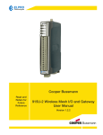
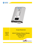
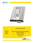
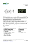
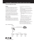
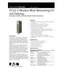
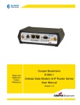
Read and
Retain for
Future
Reference
Cooper Bussmann
1050E-T
Unmanaged Ethernet Switch
User Manual
Version 1.1.5
Cooper Bussmann 1050E-T Unmanaged Ethernet Switch User Manual
Interference Issues
This Equipment has been tested and found to comply with the limits for a Class A digital device, pursuant to Part
15 of the FCC rules. These limits are designed to provide reasonable protection against harmful interference in a
commercial or industrial installation. This equipment generates, uses, and can radiate radio frequency energy. It
may cause harmful interference to radio communications if the equipment is not installed and used in accordance
with the instructions.
UL Listed Models
When operating at elevated temperature extremes, the surface may exceed +75 Celsius. For user safety, the
1050E-T should be installed in a restricted access location. The openings on the enclosure are for air convection.
Protect the equipment from overheating. DO NOT COVER THE OPENINGS.
UL Notice
The Equipment shall be powered using an external Listed Power Supply with LPS outputs or a Class 2 Power
Supply. The 1050E-T must be properly grounded for surge protection before use.
Hazardous Location Notices
This equipment is suitable for use in Class I, Division 2, Groups A, B, C, and D or non-hazardous locations only.
For Hazardous Locations operating temperature is strictly -40˚C to +60˚C only.
WARNING: EXPLOSION HAZARD
Do not disconnect equipment unless power has been removed or the area is known to be non-hazardous.
WARNING: EXPLOSION HAZARD
Substitution of any components may impair suitability for Class I, Division 2.
WARNING: EXPLOSION HAZARD
The area must be known to be non-hazardous before servicing/replacing the unit and before installing.
WARNING
Exposure to some chemicals may degrade the sealing properties of materials used in the Sealed Relay Device.
Recommendations
It is recommended to inspect the sealed relay device periodically and to check for any degradation of the materials
and to replace the complete product, not the sealed device, if any degradation is found.
Important Notice
Cooper Bussmann reserves the right to modify the equipment, its specification or this manual without prior notice,
in the interest of improving performance, reliability, or servicing. At the time of publication all data is correct for the
operation of the equipment at the voltage and/or temperature referred to. Performance data indicates typical values
related to the particular product.
No part of this documentation or information supplied may be divulged to any third party without the express
written consent of Cooper Bussmann. Products offered may contain software which is proprietary to Cooper
Bussmann. The offer or supply of these products and services does not include or infer any transfer of ownership.
Release Notice
This is the May 2013 release of the 1050E-T Unmanaged Ethernet Switch User Manual version 1.1.5.
2
www.cooperbussmann.com/wirelessresources
Rev 1.1.5
Cooper Bussmann 1050E-T Unmanaged Ethernet Switch User Manual
Follow Instructions
Read this entire manual and all other publications pertaining to the work to be performed before installing, operating, or servicing this equipment. Practice all plant and safety instructions and precautions. Failure to follow the
instructions can cause personal injury and/or property damage.
Proper Use
Any unauthorized modifications to or use of this equipment outside its specified mechanical, electrical, or other
operating limits may cause personal injury and/or property damage, including damage to the equipment. Any such
unauthorized modifications: (1) constitute “misuse” and/or “negligence” within the meaning of the product warranty,
thereby excluding warranty coverage for any resulting damage; and (2) invalidate product certifications or listings.
Rev 1.1.5
www.cooperbussmann.com/wirelessresources
3
Cooper Bussmann 1050E-T Unmanaged Ethernet Switch User Manual
CONTENTS
Chapter 1 - INTRODUCTION. . . . . . . . . . . . . . . . . . . 5
1.1 Module Identification . . . . . . . . . . . . . . . . . . . . 5
1.2 Features and Benefits. . . . . . . . . . . . . . . . . . . . 6
1.3 General Specifications. . . . . . . . . . . . . . . . . . . 6
1.4 Mechanical Specifications . . . . . . . . . . . . . . . . 7
1.5 Order Information. . . . . . . . . . . . . . . . . . . . . . . 7
Chapter 2 - GETTING STARTED. . . . . . . . . . . . . . . . 8
2.1 Package Contents . . . . . . . . . . . . . . . . . . . . . . 8
2.2 Hardware Description. . . . . . . . . . . . . . . . . . . . 8
Front Panel . . . . . . . . . . . . . . . . . . . . . . . . . . . . 8
Top View. . . . . . . . . . . . . . . . . . . . . . . . . . . . . . 8
2.3 Wiring . . . . . . . . . . . . . . . . . . . . . . . . . . . . . . . . 9
Wiring the Power Inputs. . . . . . . . . . . . . . . . . . 9
Wiring the Fault Alarm Contact . . . . . . . . . . . . 9
Grounding. . . . . . . . . . . . . . . . . . . . . . . . . . . . 10
2.4 LED Indications, Ports, and Cabling. . . . . . . . 10
LED Indicators . . . . . . . . . . . . . . . . . . . . . . . . 10
Ports. . . . . . . . . . . . . . . . . . . . . . . . . . . . . . . . 10
Cabling . . . . . . . . . . . . . . . . . . . . . . . . . . . . . . 11
2.5 Mounting Installation . . . . . . . . . . . . . . . . . . . 11
DIN-rail Mounting . . . . . . . . . . . . . . . . . . . . . . 11
Wall Mount Plate Mounting . . . . . . . . . . . . . . 12
Appendix A - GLOSSARY . . . . . . . . . . . . . . . . . . . . 13
4
www.cooperbussmann.com/wirelessresources
Rev 1.1.5
Cooper Bussmann 1050E-T Unmanaged Ethernet Switch User Manual
Chapter 1 - INTRODUCTION
The 1050E-T Ethernet Switch from Cooper Bussmann is a cost-effective solution that meets the high
reliability requirements demanded by industrial applications. The 1050E-T is a 5-port 10/100TX Slim Type Industrial
Unmanaged Switch that includes the following features.
High-Speed Transmissions
The Industrial Switch includes a switch controller that can automatically sense transmission speeds (10/100Mbps).
The RJ-45 interface can also be auto-detected, so MDI or MDIX is automatically selected and a crossover cable is
not required. All Ethernet ports have memory buffers that support the store-and-forward mechanism. This assures
that data is properly transmitted.
Dual Power Input
To reduce the risk of power failure, the Industrial Switch provides +12 Vdc to +48 Vdc dual power inputs. If there is
power failure, Industrial Switch will automatically switch to the secondary power input.
Flexible Mounting
The Industrial Switch is extremely compact and can be mounted on a DIN-rail or a wall so it is suitable for any
space-constrained environment.
Advanced Protection
The power line of the 1050E-T supports up to 3,000 Vdc EFT (Electrical Fast Transient) protection, which secures
equipment against unregulated voltage and makes systems safer and more reliable. Its 6,000 V ESD protection for
Ethernet ports makes the 1050E-T suitable for harsh environments.
Wide Operating Temperature
The operating temperature of the 1050E-T is between -40°C and 75°C. Given this wide range, you can use the
Industrial Switch in some of the harshest industrial environments.
Easy Troubleshooting
LED indicators make troubleshooting quick and easy. Each 10/100 Base-TX port has 2 LEDs that display the link
status, transmission speed and collision status. Also the three power indicators P1, P2 and Fault help you diagnose
problems immediately.
1.1 Module Identification
The module identification label can be found on the bottom of your 1050E-T device. This label contains the model
number, temperature range, power range, serial number, and all certifications.
Rev 1.1.5
www.cooperbussmann.com/wirelessresources
5
Cooper Bussmann 1050E-T Unmanaged Ethernet Switch User Manual
1.2 Features and Benefits
• IEEE 802.3 10Base-T, 802.3u 100Base-TX
• Flow control on full duplex
• RJ-45 connectors with auto MDI/MDIX functionality
• Store-and-forward switching architecture
• Relay alarm contact for system events
• UL Class I Division II for Group A,B,C, and D hazardous locations
• Supports surge protection 3,000 Vdc for power line
• Supports 6,000 Vdc Ethernet ESD protection
• Supports redundant +12 Vdc to +48 Vdc power input
• Provides flexible mounting: DIN-rail, Wall Mounting
• Supports operating temperatures from -40°C to 75°C
1.3 General Specifications
Product specifications are subject to change without notice.
Ethernet Standards/Transfer
Rate
Standards
10Base-T Ethernet (IEEE 802.3)
100Base-TX Ethernet (IEEE 802.3u)
Flow Control and Backpressure (IEEE 802.3x)
Transfer Rate
10 Mbps (IEEE 802.3)
100 Mbps with Auto-Negotiation (IEEE 802.3u)
Fault Alarm
Fault Alarm Contact
Alarm for System Events
1 Relay Output, 1A MAX @ 24 Vdc or 24 Vac
Ethernet Port
Connectors
RJ-45
Network Cabling
10Base-T: 2-pair UTP/STP Cat. 3,4,5,6 cable EIA/TIA-568 100-ohm
(100m/328)
100Base-TX: 2 pair UTP/STP Cat. 5,6 cable EIA/TIA-568 100-ohm
(100m/328)
Protocols Supported
Multiple Access Protocol – Carrier sense multiple access with
collision detection (CSMA/CD)
User Configuration
N/A
LED Indication
Power OK; Fault Condition Exists
Port LED Indication
Link Active, Full Duplex/Collision
Protocols/Configuration
LED Indication/Diagnostics
Network Management N/A
Compliance
6
EMI and EMC
FCC Part 15 – Class A; CE EN61000-4-2 (ESD),
CE EN61000-4-3 (RS), CE EN61000-4-4 (EFT),
CE EN61000-4-5 (Surge), CE EN61000-4-6 (CS),
CE EN61000-4-8, CE EN61000-4-11,
CE EN61000-4-12, CE EN61000-6-2, CE EN61000-6-4
Hazardous Area
UL Class I, Division 2
Maximum Ambient Temperature +60˚C
Safety
CE/EN60950-1
UL
UL Listed
www.cooperbussmann.com/wirelessresources
Rev 1.1.5
Cooper Bussmann 1050E-T Unmanaged Ethernet Switch User Manual
General
Power Supply
Size
30 mm x 95 mm x 140 mm (1.18” x 3.74” x 5.51”)
Housing
Painted Metal Case; IP30
Mounting
DIN Rail or Wall-mount
Terminal Blocks
Removable; Max conductor 12 AWG (2.5 sqmm)
Temperature Rating
-40°C to +75°C (-40°F to 167°F)
Humidity Rating
5% - 95% RH Non-condensing
Weight
0.43 kg (0.95 lb)
Nominal Supply
12 Vdc to 48 Vdc; Under/Over Voltage Protection and Reverse
Polarity
Maximum Current
Draw
450 mA
1.4 Mechanical Specifications
The following diagram shows the exterior dimensions of the 1050E-T Ethernet switch.
1.5 Order Information
Item
Product Code
Description
Ethernet Switch
1050E-T
Basic Ethernet Switch
Power Supply
PS-DINAC-24DC-OK
AC/DC Adapter, 24 Vdc, 2.5 A, 60 W, -20 to +70°C
Rev 1.1.5
www.cooperbussmann.com/wirelessresources
7
Cooper Bussmann 1050E-T Unmanaged Ethernet Switch User Manual
Chapter 2 - GETTING STARTED
2.1 Package Contents
• 1050E-T Ethernet Switch x 1
• Pluggable Terminal Block x 1
• Wall Mounting Plate x 2
2.2 Hardware Description
Front Panel
The front panel of the 5-port 10/100BaseTX Industrial Switch is shown below.
Top View
The top panel of the 5-port 10/100BaseTX Industrial Switch is equipped with one terminal block connector of two
power inputs.
8
www.cooperbussmann.com/wirelessresources
Rev 1.1.5
Cooper Bussmann 1050E-T Unmanaged Ethernet Switch User Manual
2.3 Wiring
Wiring the Power Inputs
Follow these steps to insert the power wire.
1. Insert the positive and negative wires into the V+ and V- contacts on the terminal block connector.
2. When using a single power supply to power the device, connect the power supply to both power inputs to
ensure that the fault alarm is not set. (Connect V+ to both pins 2 and 6, and then connect V- to both pins 1
and 5.)
3. Tighten the wire-clamp screws to prevent the wires from coming loose.
Wiring the Fault Alarm Contact
The fault alarm contact is in the middle of terminal block connector, as shown below. The contact will be closed for
normal operation, and will open in the case of a power failure from either of the two power inputs.
1. Insert the wires into the fault alarm contact (number 3 and 4).
NOTE The wire gauge for the terminal block should be in the range between 12 and 24 AWG.
Rev 1.1.5
www.cooperbussmann.com/wirelessresources
9
Cooper Bussmann 1050E-T Unmanaged Ethernet Switch User Manual
Grounding
To provide maximum surge and lightning protection, the 1050E-T should be effectively grounded via a GND screw
located on the top of the unit next to the terminal connector block. All ground (earth) wiring should be minimum
14 AWG.
2.4 LED Indications, Ports, and Cabling
LED Indicators
Three LEDs display the power status, and an additional ten LEDs display the network status. These LEDs are
located on the front panel of the switch and are described in the following table.
LED
Color
Description
P1
Green
On
Power input 1 is active
Off
Power input 1 is inactive
P2
Green
On
Power input 2 is active
Off
Power input 2 is inactive
Fault
Red
On
Power input 1 or 2 is inactive
Off
Power input 1 and 2 are both functional, or no power inputs
On
Connected to network
Flashing
Networking is active
Off
Not connected to network
On
Ethernet port full duplex
Flashing
Collision of packets occurs
Off
Ethernet port half duplex or not connect to network
Link/Active
(1~5)
Duplex/Collision
(1~5)
Green
Orange
Ports
10
www.cooperbussmann.com/wirelessresources
Rev 1.1.5
Cooper Bussmann 1050E-T Unmanaged Ethernet Switch User Manual
The RJ-45 ports (Auto MDI/MDIX) are auto-sensing for 10Base-T or 100Base-TX devices connections. Auto MDI/
MDIX means that you can connect to another switch or workstation without changing straight through or crossover
cabling (see the following schematics).
Cabling
Use the four twisted-pair Category 5 cabling for RJ-45 port connection. The cable length between the switch and
the link partner (switch, hub, or workstation) must be less than 100m (328 ft).
2.5 Mounting Installation
DIN-rail Mounting
The 1050E-T ships from the factory with the DIN-rail mount kit installed. Follow these steps to mount the 1050E-T.
1. Insert the top of DIN-rail into the track.
2. Lightly push the button of DIN-rail into the track.
Rev 1.1.5
www.cooperbussmann.com/wirelessresources
11
Cooper Bussmann 1050E-T Unmanaged Ethernet Switch User Manual
3. Check the module is firmly secured to the DIN-rail track.
To remove the Industrial Switch from the track, reverse steps above.
Wall Mount Plate Mounting
Follow these steps to mount the switch using the wall mount plate. Unscrew the screws to remove the DIN-rail
mount from the switch.
1. Fit the wall mount plates to the top and bottom ends of the switch.
2. Use the mounting screws to secure the wall mount plate to the switch.
3. Mount using the wall mount holes provided.
To remove the wall mount plate, reverse the steps above.
12
www.cooperbussmann.com/wirelessresources
Rev 1.1.5
Cooper Bussmann 1050E-T Unmanaged Ethernet Switch User Manual
Appendix A - GLOSSARY
Term
Definition
100Base-TX
100Base-TX is a Fast Ethernet cabling standard. 100Base-TX devices can transfer data at a
rate of up to 100 Mbps, and use two wire-pairs of wires inside a category 5 or above cable.
10Base-T
10Base-T is an Ethernet cabling standard. 10Base-T devices can transfer data at a rate of up
to 10 Mbps, and use twisted pairs of wires in their Ethernet cabling.
AWG
American wire gauge (AWG), also known as the Brown & Sharpe wire gauge, is a standardized wire gauge system used predominantly in the United States and Canada for the
diameters of round, solid, nonferrous, electrically conducting wire.
CSMA/CD
Carrier Sense Multiple Access/Collision Detection is the access method used on an Ethernet
network. A network device transmits data after detecting that a channel is available. However,
if two devices transmit data simultaneously, the sending devices detect a collision and
retransmit after a random time delay.
DIN rail
A DIN rail is a metal rail of a standard type widely used for mounting circuit breakers and
industrial control equipment inside equipment racks.
ESD
Electrostatic discharge (ESD) is discharge of static electricity from a outside source, such as
human hands, into an integrated circuit, often resulting in damage to the circuit.
FCC
The Federal Communications Commission (FCC) is the US agency that regulates interstate
and international wire, radio, and other broadcast trasmissions, including telephone,
telegraph, and telecommunications.
Full Duplex
A full-duplex (or double-duplex) system allows communication in both directions and, unlike
half-duplex, allows this to happen simultaneously. Land-line telephone networks are examples of full-duplex, since they allow both callers to speak and be heard at the same time.
IEEE
Institute of Electrical and Electronics Engineers, New York, www.ieee.org. A membership
organization that includes engineers, scientists and students in electronics and allied fields.
It has more than 300,000 members and is involved with setting standards for computers and
communications.
MDI/MDIX
Medium Dependent Interface (MDI) describes the interface (both physical and electrical) in
a computer network from a physical layer implementation to the physical medium used to
carry the transmission. Ethernet over twisted pair also defines a medium dependent interface
crossover (MDIX) interface. Auto-MDIX ports on newer network interfaces detect if the connection would require a crossover, and automatically chooses the MDI or MDIX configuration
to properly match the other end of the link.
RJ-45
Standard connectors used in Ethernet networks. RJ-45 connectors are similar to standard
RJ-11 telephone connectors, except that RJ-45 connectors can have up to eight wires,
whereas telephone connectors have four wires.
Switch
A type of hub that efficiently controls the way multiple devices use the same network so that
each can operate at optimal performance. A switch acts as a networks traffic cop. Rather
than transmitting all the packets it receives to all ports as a hub does, a switch transmits
packets to only the receiving port.
UL
Underwriter Laboratories (UL) is one of several companies approved to perform safety testing
by the US federal agency Occupational Safety and Health Administration (OSHA).
Rev 1.1.5
www.cooperbussmann.com/wirelessresources
13
Cooper Bussmann 1050E-T Unmanaged Ethernet Switch User Manual
Notes:
14
www.cooperbussmann.com/wirelessresources
Rev 1.1.5
Customer Assistance
North America & Latin America
Technical Support:
United States:+1 866 713 4409
Australasia.: +61 7 3352 8624
Other: +1 604 944 9247
Email: [email protected]
Website: www.cooperbussmann.com/wireless
Australasia Fax: +61 7 33528677
US Fax: +1 925 924 8502
Online Resources
Visit www.cooperbussmann.com/wirelessresources
for the following resources and more:
• User Manuals
• Installation Guides
• Configuration Software
• Datasheets
• Dimensional Drawings
5735 W. Las Positas Suite 100
Pleasanton, California 94588 USA
Telephone: +1 925 924 8500
[email protected]
Australia, New Zealand
Cooper Technology Centre
Suite 2.01, Quad 2, 8 Parkview Drive
Sydney Olympic Park, NSW, 2127, AUSTRALIA
Telephone: +61 2 8787 2777
[email protected]
China
955 Shengli Road
East Area of Zhangjiang High-Tech Park
Shanghai, 201201, CHINA
Telephone: +86 21 2899 3600
[email protected]
Southeast Asia
2 Serangoon North Avenue 5
# 06-01 Fu Yu Building, 554911, SINGAPORE
Telephone: +65 6645 9888
[email protected]
©2013 Cooper Bussmann
www.cooperbussmann.com /wireless
Your Authorized Cooper Bussmann Distributor is:
The trade names and brand names contained herein are valuable trademarks of Cooper Industries in the U.S. and other countries. You are not
permitted to use the Cooper Trademarks without the prior written consent of Cooper Industries.
Rev 1.1.5
www.cooperbussmann.com/wirelessresources