1
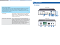
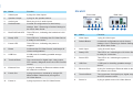
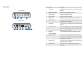
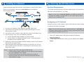
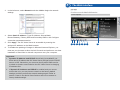
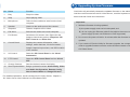
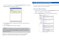
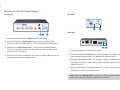
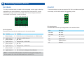
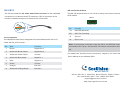
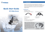
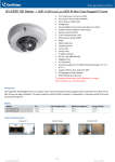
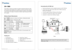
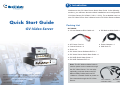
1
Introduction
Welcome to the GV-Video Server Quick Start Guide. In the following
sections, you will learn about the basic installations and configurations of the
GV-Video Server (GV-VS04H / VS11 / VS12). For a detailed user’s manual,
see GV-Video Server User’s Manual on the GV-Video Server software DVD.
Quick Start Guide
GV-Video Server
Packing List
GV-VS04H
● 3.5 mm Stereo to RCA Cable x 2
● DC Male-to-Male Cable x 1
● AC Power Cord x 1
● Power Adaptor x 1
● Conical Anchor x 4
● Wall Hook x 1
● Screw x 4
● GV-Video Server Software DVD x 1
● GV-Video Server Quick Start Guide x 1
● GV-NVR Quick Start Guide x 1
● GV-NVR Software DVD x 1
Note: The DC Male-to-Male Cable is
used to power on the camera through
the GV-Video Server. You can also
optionally purchase three more DC
Male-to-Male Cables and one DC
Thank you for purchasing GV-Video Server (GV-VS04H / VS11 / VS12). This guide is
1-Male to 4-Female Cable to power on
designed to assist the new user in getting immediate results from the GV-VS04H / VS11 /
VS12. For advanced information on how to use the GV-VS04H / VS11 / VS12, please refer
to GV-Video Server User's Manual on Software DVD.
© 2012 GeoVision Inc. All rights reserved.
2012/01
English
VS041112-QG-B
four cameras through the GV-Video
Server.
DC 1-Male to
4-Female Cable
DC Male-to-Male
Cable
GV-VS11
Options
● Power Adaptor x 1
GV-GPS Receiver
The GV-GPS Receiver is a Global Position
System receiver. With the GV-GPS Receiver,
you can perform GPS tracking and location
verification of the GV-Video Server. Two types
of interfaces are available: UART (for
GV-VS04H) and RS-232 (for GV-VS12).
GV-Relay V2
Working with the GV-Relay V2, the GV-Video
Server is capable of driving the loads of relay
outputs over 5 volts.
GV-Storage System
The iSCSI storage system allows you to record
files over the Internet.
GV-WiFi USB Adaptor
The WiFi USB Adaptor is designed to connect
the GV IP devices, such as GV-Video Server or
GV-Compact DVR, to the wireless network.
● GV-Video Server Software DVD x 1
● GV-Video Server Quick Start Guide x 1
● GV-NVR Quick Start Guide x 1
● GV- NVR Software DVD x 1
GV-VS12
● I/O Cable with RJ-45 Connector x 1
● Sticker (for positioning conical anchors) x 1
● AC Power Cord x 1
● Power Adaptor x 1
● Wall Hook x 1
● Screw x 4
● Conical Anchor x 4
● GV-Video Server Software DVD x 1
● GV-Video Server Quick Start Guide x 1
● GV-NVR Quick Start Guide x 1
● GV-NVR Software DVD x 1
GV-PA191 PoE Adaptor The GV-PA191 is designed to provide power to
the IP device through a single Ethernet cable.
The GV-PA191 is only supoprted by GV-VS04H
and GV-VS12.
GV-VR605 DC Voltage
Regulator
With the GV-VR605, you can install GV-Video
Server in the car. The GV-VR605 will supply and
maintain a 12V voltage to the GV-Video Server
and its connected cameras. The GV-VR605 is
only supported by GV-VS04H and GV-VS12.
2
Overview
GV-VS04H
Access Control Series
Front View
The GV-Video Server can work with the Wiegand-interface card reader
to send cardholder data to the central monitoring stations Center V2
and VSM, as well as GV-System (DVR). The following devices are only
supported by GV-VS04H.
GV-Reader
GV-Reader includes transmit-receive antenna
and electronics. Featured with the Wiegand
output, the unit is compatible with any standard
access control panel.
1
2
3
4
5
Rear View
GV-R1352 Card Reader The GV-R1352 is a card reader designed to
recognize identification cards. Featured with the
Wiegand output, the unit can be connected to
any standard access control panel. The
GV-R1352 comes with a weather sealed and
IP66 compliant housing for outdoor use.
9
10
11
12
13
6 7 8
No. Name
Function
1
Video Input
4 plugs for video inputs.
2
Speaker Output
A plug for the speaker device.
3
Audio Input
Each plug is for 2 audio inputs.
4
Default Button
It resets all configurations to their factory
settings. See 7 Restoring to Default Settings in
the Quick Start Guide.
5
6
Disk Full/Fault LED
Ready LED
This LED is on, indicating the hard drive is full
or faulty.
This LED is on, indicating the GV-Video Server
is ready for connection.
7
Power LED
This LED is on, indicating the power is
supplied.
8
Reset
It reboots the GV-Video Server, and keeps all
current configurations.
9
USB Port
2 USB ports for installing portable storage
devices.
10
Terminal Block
The connectors for digital input, relay output,
PTZ camera, Wiegand device and GPS module
control.
11
Ethernet Port
A plug for inserting an Ethernet cable to build
the network connection.
12
Power Out
A plug to power on cameras by using a DC
Male-to-Male Cable directly through the
GV-Video Server.
13
Power In
A plug to power on the GV-Video Server.
GV-VS11
Front View
1
2
3
Rear View
4
5
6
7
8
9
No. Name
Function
1
Video Input
1 plug for video input.
2
Default Button
It resets all configurations to their factory
settings. See 7 Restoring to Default Settings in
the Quick Start Guide.
3
Audio Input
1 plug for audio input.
4
Ready LED
This LED is on, indicating the GV-Video Server
is ready for connection.
5
Power LED
This LED is on, indicating the power is
supplied.
6
USB Port
1 USB port for installing portable storage
device.
7
Ethernet Port
A plug for inserting an Ethernet cable to build
the network connection.
8
Terminal Block
The connectors for digital input, digital output
and PTZ camera control.
9
Power In
A plug to power on the GV-Video Server.
GV-VS12
Front View
1
2
3
4
Rear View
5
6
7
8
No. Name
Function
1
USB Port
1 USB port for installing the portable storage
device.
2
Speaker Output
A plug for the speaker device.
3
Audio Input
2 plugs for audio inputs.
4
Video Input
2 plugs for video inputs.
5
Power In
A plug to power on the GV-Video Server.
6
Ethernet Port
A plug for inserting an Ethernet cable to build
the network connection.
7
USB Port
1 USB port for installing the portable storage
device.
8
I/O / PTZ Port
A port for digital input, relay output and PTZ
camera control. Insert the I/O Cable with RJ-45
Connector to this port.
9
RS-232
Terminal Block
The connectors for GPS module control.
10
Default Button
It resets all configurations to their factory
settings. See 7 Restoring to Default Settings in
the Quick Start Guide.
11
Ready LED
This LED is on, indicating the GV-Video Server
is ready for connection.
12
Power LED
This LED is on, indicating the power is
supplied.
9 10 11 12
3
4
Installing on a Network
These instructions describe the basic connections to install the GV-Video
Server on the network. Here we use GV-VS04H as an example to
demonstrate the steps.
Accessing the GV-Video Server
System Requirement
To access the Web interface of the GV-Video Server, it is required to use
Microsoft Internet Explorer 7.x or later.
Note: For the users of Internet Explorer 8, additional settings are
1
2
required. For details, see Appendix C in GV-Video Server User’s
Manual on the software DVD.
3
5
4
Assigning an IP Address
Designed for use on the network, the GV-Video Server must be assigned an
IP address to make it accessible.
1. Connect your camera’s video output to the BNC video input.
2. Connect the microphone to the RCA audio input using the 3.5 mm
Stereo to RCA Cable.
3. Connect the hub or switch on the LAN to the unit’s 10/100 Mbps port.
4. Connect power using one of the following methods:
●
Use the supplied power adapter, connect to power.
●
Use the Power over Ethernet (PoE) function. The power will be
provided over the network cable.
5. Optionally connect the DC Male-to-Male Cable to power on the camera
through the GV-Video Server.
Note: The GV-Video Server has a default address of 192.168.0.10. The
computer used to set the IP address must be under the same network
or IP sequence assigned to the unit.
1. Open your Web browser, and type the default IP address
http://192.168.0.10
2. In both Login and Password fields, type the default value admin. Click
Apply.
6. Wait until both Power and Ready LEDs are on and then you can set
the IP address for the unit. See 4. Accessing the Camera later in the
Quick Start Guide.
Note: 1. The GV-VS11 does not support PoE function.
2. The DC Male-to-Male Cable and 3.5 mm Stereo to RCA Cable
are only available for GV-VS04H.
3. The GV-Video Server cannot work with the microphone
requiring power from the unit. Use the microphone that has
external power supply.
Continued on the reverse
5
The Web Interface
3. In the left menu, select Network and then LAN to begin the network
settings.
12
11
10
9
4. Select Static IP address. Type IP Address, Subnet Mask,
Router/Gateway, Primary DNS and Secondary DNS in the Configure
connection parameters section.
5. Click Apply. The GV-Video Server is accessible by entering the
assigned IP address on the Web browser.
6. To enable the updating of images in Microsoft Internet Explorer, you
must set your browser to allow ActiveX Controls and perform a one-time
installation of GeoVision’s ActiveX component onto your computer.
Important:
1. Dynamic IP Address and PPPoE should only be enabled if you
know which IP address the GV-Video Server will get from the DHCP
server or ISP. Otherwise, you must use the Dynamic DNS service
to obtain a domain name linked to the GV-Video Server’s changing
IP address first.
2. If Dynamic IP Address and PPPoE is enabled and you cannot
access the unit, you may have to reset it to the factory default
settings and then perform the network settings again. Refer to
section 7 later in the Quick Start Guide to see how to restore to
factory default settings.
1
2
3
4
5
6
7
8
6
Upgrading System Firmware
No. Name
Function
GeoVision will periodically release the updated firmware on the website. To
1
Play
Plays live video.
load the new firmware into the GV-Video Server, read the important notes
2
Stop
Stops playing video.
3
Microphone
Talks to the surveillance area from the local
computer.
Important:
1. While the firmware is being updated,
4
Speaker
Listens to the audio around the camera.
5
Snapshot
Takes a snapshot of live video.
6
File Save
Records live video to the local computer.
7
Full Screen
Switches to full screen view. Right-click the
image to have these options: Snapshot, PIP,
PAP, Zoom In and Zoom Out.
8
Control Panel
Displays the camera information, video
settings, audio data rate, I/O device status,
images captured upon alarm, and GPS location
of the camera.
9
I/O Control
Starts the I/O Control Panel or the Visual
Automation.
10
PTZ Control
Starts the PTZ Control Panel and the Visual
PTZ.
11
Change Camera
Sets the desired camera for display.
12
Show System Menu
Brings up these functions: Alarm Notify, Video
and Audio Configuration, Remote Config,
Show Camera Name and Image Enhance.
For detailed operations, see Accessing the GV-Video Server, Chapter 3,
GV-Video Server User's Manual on the software DVD.
below and then follow the instructions.
A) the power supply must not be interrupted, and
B) do not unplug the Ethernet cable if the cable is the source of
power supply (Power over Ethernet or PoE supported).
2. Do not turn the power off within 10 minutes after the firmware is
updated.
3. If you use the IP Device Utility for firmware upgrade, the computer
used to upgrade firmware must be under the same network of the
GV-Video Server.
7
1. In the Live View window, click the Show System Menu button and select
Remote Config. This dialog box appears.
Restoring to Default Settings
You can restore the camera to factory default settings using the Web
interface or directly on the GV-Video Server.
Using the Web Interface:
1. On the left menu of Web interface, select Management and select
Tools. The Additional Tools dialog appears.
2. Click the Load Default button in the System Settings section.
2. Click the Browse button to locate the firmware file (.img) saved at your
local computer.
3. Click the Upgrade button to start the upgrade.
WARNING: The interruption of power supply during updating causes
not only update failures but also damages to the camera. In this case,
please contact your sales representative and send your device back to
GeoVision for repair.
For details on upgrading system firmware, see Advanced Applications,
Chapter 6, GV-Video Server User's Manual on the software DVD.
Directly on the GV-Video Server:
GV-VS04H
GV-VS11
2
4
GV-VS12
2 1
4
1. Press and then release the Reset button immediately.
2. Press and hold the Load Default button until all 3 LEDs (Power,
Ready and Disk Full/Fault) are on. This may take about 30 seconds.
3. Release the Load Default button. The process of loading default
values is complete, and the GV-Video Server starts rebooting itself
with all 3 LEDs turning off.
4. Wait until the Power and Ready LEDs turn on again. After this, all the
settings are returned to default values.
2
4
1. Unplug and plug the power cable to start.
2. Press and hold the Default button until the Ready LED blinks. This
may take about 30 seconds. The Ready LED will blink twice.
3. Release the Default button. The process of loading default values is
complete, and the GV-Video Server starts rebooting itself with the 2
LEDs turning off.
4. Wait until the Power and Ready LEDs turn on again. After this, all the
settings are returned to default values.
Note: Before the Ready LED is on again, do not unplug the power
cable; otherwise the loading of default values will fail.
8
Connecting Auxiliary Devices
GV-VS04H
GV-VS11
The 16-pin terminal block, located on the rear panel, can be used to develop
The terminal block on the rear panel of GV-VS11 provides one digital input
applications for motion detection, event alerts via E-mail and FTP, center
and output, an RS-485 interface and auxiliary power.
- + 5V
monitoring through Center V2 and VSM, PTZ control, Wiegand-interface
card reader and a variety of other functions.
2
4
6
8 10 12 14 16
DI DO G
1
3
5
7
9 11 13 15
Pin Assignment
The table below lists the pin assignment for the terminal block.
Pin Function
Pin Function
1
Relay Output 1
9
DC 5V Out for GV-Relay Module, or GPS Module
2
Digital Input 1
10
Ground, or GPS Ground
3
Relay Output 2 11
RS 485+
4
Digital Input 2
Wiegand D0, or GPS RX
5
Relay Output 3 13
RS 485-
6
Digital Input 3
Wiegand D1, or GPS TX
7
Relay Output 4 15
Ground
8
Digital Input 4
DC 12V Out for Wiegand Card Reader
12
14
16
Note: To connect the GPS module, use the Pin 9 for power supply, Pin
10 for ground, Pin 12 for GPS RX and Pin 14 for GPS TX.
Pin Assignment
The table below lists the pin assignment for the terminal block.
Pin
Function
RS-485-
RS-485-
RS-485+
RS-485+
5V
DC 5V Out
DI
Digital Input
DO
Digital Output
G
Ground
RS-232 Terminal Block
GV-VS12
GV-VS12 provides the I/O Cable with RJ-45 Connector for the extensible
connection to I/O devices and PTZ cameras. A RJ-45 connector and a
The RS-232 terminal block on GV-VS12 is mainly used for the connection to a
GPS module.
RS232
bundle of shielded wires are on the each end of the cable.
TX RX G 5V
Pin
Function
TX
GPS RX (Receive)
RX
GPS TX (Transmit)
Pin Assignment
G
Ground
The table below lists the pin assignment for the shielded wires of the I/O
5V
DC 5V Out
Cable with RJ-45 Connector.
Wire
Function
1
Brown
Digital Out 1
2
White with Brown Stripe
Digital Out 2
3
White with Green Stripe
Ground
4
White with Blue Stripe
Digital In 1
5
Blue
Digital In 2
6
Green
Ground
7
Orange
RS-485 -
8
White with Orange Stripe
RS-485 +
Pin
Note: To ensure the connection to the GV-VS12, the GPS RX must be
connected to the TX pin, and the GPS TX must be connected to the RX
pin.
For details, see Auxiliary Device Connectors, Chapter 9, GV-Video Server
User's Manual on the software DVD.
9F, No. 246, Sec. 1, Neihu Rd., Neihu District, Taipei, Taiwan
Tel: +886-2-8797-8376 Fax: +886-2-8797-8335
[email protected]
http://www.geovision.com.tw