1
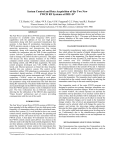
Force7 Industrial
All-in-One Cellular ,Wifi and HDTV Booster
User Guide
WARNING
This is NOT a CONSUMER device. It is designated for installation
by FCC LICENSEES and QUALIFIED INSTALLERS. You MUST
have an FCC LICENSE or express consent of an FCC Licensee to
operate this device. Unauthorized use may result in significant
forfeiture penalties, including penalties in excess of $100,000
for each continuing violation.
HAPTER 1: Introduction 1
C
1.1 - Package Contents
3
1.2 - Features & Benefits 3
1.3 - Additional Items Needed
3
1.4 - How It Works
4
CHAPTER 2: Safety
4
2.1 - Safety Warnings
4-5
CHAPTER 3: Planning
6
3.1 - Overview
6
3.2 - Exterior Antenna
7
3.3 - Interior Antennas
8
3.4 - Antenna Separation
9-10
3.5 - Calculating Signal Strength
10-11
3.6 - Booster Location
12
3.7 - Accessories
12
3.8 - Need Help?
12
CHAPTER 4: Installation
13
4.1 - Selecting the Locations
13
4.2 - Soft Installation
13
4.3 - Exterior Antenna
13-14
4.4 - Internal Antennas
15
4.5 - Mounting the Booster
16
CHAPTER 5: Configuration & Testing
17
5.1 - DIP Switches and Lights
17-18
5.2 - Initial Configuration 19
5.3 - Powering on the Booster
19
5.4 - Testing
19
5.5 - Adjusting the Booster
19-20
5.6 - Automatic Shutdown
20-21
CHAPTER 6: HDTV & Wifi Installation
21
CHAPTER 7: Warranty
21
6.1 - Warranty Periods
21
6.2 - Warranty Information
22
6.3 - Contact Information
23
Notes:15.19(a): This device complies with part 15 of the FCC Rules. Operation is subject to the following two conditions (1) This
device may not cause harmful interference, and (2) this device must accept any interference received including interference that
may cause undesired operation.
2
SureCall | 48346 Milmont Drive, Fremont CA 94538 | 1-888-365-6283 | [email protected]
Introduction
Introducing SureCall’s Force5, Industrial booster Please read this entire manual before proceeding.
with the installation. This manual applies to the Force5 Industrial model
1.1 - Package Contents
Your booster box contains the following items:
• TBD
• Mounting kit (not shown).
• DC power supply (not shown).
• Wall anchors (not shown).
1.2 - Features & Benefits
The booster offers the following features
and benefits:
• Powerful in-building booster with 31dB of adjustable gain level.
• Extends cellular signals in areas with poor coverage due to geographical location and/or building
design.
• Suitable for large areas up to approximately 80,000 square feet depending on outside signal
strength and carrier frequency.
• Maximum output power is 3 watts EIRP for cellular, 2watts EIRP for PCS and 1 watt for AWS
1710-1755 MHz bands. Fixed stations operating in the 1710-1755 MHz bands are limited to a
• Automatic oscillation detection and protection system powers down the booster to prevent harmful radio interference.
1.3 - Additional Items Needed
SC-288W
maximum antenna height of 10 meters above ground.
The booster requires the following additonal components for a
complete installation:
• External antenna (such as the SC-288W omni by SureCall).
• Lightning protector (SC-LP).
• Cable splitter if installing multiple antennas.
• Sufficient SC-400 ultra low loss interior/exterior cable of 50 ohm.
• Multiple antennas (such as the SC-222W, omnidirectional domes by SureCall).
• HDTV Antenna & HDTV Coax
• Grounded surge suppressor for DC power supply.
Note: Due to the recent change of our company name from Cellphone-Mate (CM) to SureCall (SC) we have changed the prefix on all of our
antennas, cables and accessories from CM to SC-.
SureCall | 48346 Milmont Drive, Fremont CA 94538 | 1-888-365-6283 | [email protected]
3
Safety
1.4 - How It Works
The Force5 booster amplifies cellular signals from the nearest tower to phones in
SC-222W
a building and from those phones back to the tower to compensate for weak
reception caused by distance, topography, building structure, and/or other
reasons. The booster receives the signal from an outside antenna, amplifies that
signal, and then rebroadcasts it via the interior antenna(s) where it is picked up
by cellular phones, modems, and data cards. The interior antennas also pick
up signals from cellular devices and pass them to the booster. The booster
amplifies these signals and passes them to the exterior antenna for
rebroadcast back to the tower.
CHAPTER 2: Safety
This chapter contains important safety information designed to prevent personal
injury, equipment malfunction, and/or radio interference. You are responsible for
ensuring a safe installation.
2.1 - Safety Warnings
• You are responsible for knowing and following all applicable codes and regulations and for obtaining all
required permits and inspections.
• Follow all safety precautions contained in this Installation Manual.
• The installation process may require working in high locations such as roofs and/or ladders. Follow applicable safety regulations and best practices to avoid falling. Take care not to drop objects off any high
area. Cordon off ground areas directly below roof or ladder work when possible.
• Always use appropriate personal protective equipment such as goggles, gloves, hard hat, etc. as needed
and as required.
WARNING: FAILURE TO EXERCISE CAUTION WHEN
WORKING IN HIGH AREAS COULD CAUSE A FALL
AND PERSONAL INJURY.
4
SureCall | 48346 Milmont Drive, Fremont CA 94538 | 1-888-365-6283 | [email protected]
Safety
• Some components may be heavy and/or bulky. Always use proper lifting and carrying techniques when
handling components, especially when working on a ladder, roof, or other area with a fall hazard.
• The exterior antenna must not be co-located or operating in conjunction with any other antenna.
• Always use a properly installed SureCall lightning protector between the exterior antenna and the
booster.
CAUTION: FAILURE TO PROPERLY INSTALL A
LIGHTNING PROTECTOR CAN RESULT IN DAMAGE TO THE BOOSTER, ANTENNAS, AND WIRING.
•Always power off the booster before working on the roof of the building or anywhere in close proximity
to the external antenna.
• Allow at least 24 inches (60cm) of separation between interior antennas and humans or animals.
• Allow at least 24 inches (60cm) of separation between exterior antennas and all persons.
• Comply with all antenna separation requirements to prevent signal oscillation.
CAUTION: SIGNAL OSCILLATION CAN CAUSE
RADIO INTERFERENCE WITH CELLULAR TOWERS
AND RESULT IN CIVIL AND/OR CRIMINAL
PENALTIES.
SureCall | 48346 Milmont Drive, Fremont CA 94538 | 1-888-365-6283 | [email protected]
5
Planning
CHAPTER 3: Planning
3.1 - Overview
The general booster installation process follows these steps:
1. Decide where to mount the exterior antenna. This will generally be on the wall or roof of the building in
the location with the strongest signal. You will need to decide whether to use an omnidirectional antenna
mounted vertically or a directional Yagi antenna pointed directly at the cellular tower (line of sight). You
must also consider attaching a grounded lightning protector between the exterior antenna and the
booster.
2. Decide where to mount the interior antenna(s), being sure to take separation requirements into account.
In general, long narrow spaces will benefit most from directional flat-panel antennas while more square
spaces will benefit more from omnidirectional dome antennas.
3. Decide where to mount the booster. This should be in a secure indoor location near a grounded power
source.
4. Decide where to route the cables between the exterior antenna and the booster and between the
booster and interior antennas.
5. Install the antennas as described in their respective Installation Manuals.
6. Route the cables to the booster location.
7. Install the booster as described in this manual.
8. Power on the booster and perform the configuration and testing as described in this manual.
6
SureCall | 48346 Milmont Drive, Fremont CA 94538 | 1-888-365-6283 | [email protected]
Planning
3.2 - Exterior Antenna
You may use either an omnidirectional antenna such as the SC-288W (flat area with no obstructions)
or a directional Yagi antenna such as the SC-230W (to point directly at the tower). The omnidirectional
antenna receives and transmits signals over a horizontal 360-degree circle while the Yagi antenna
receives and transmits signals over a focused area and must be aimed directly (line of sight) toward the
cellular tower that provides the best signal to the building.
The exterior antenna and mast (if any) must be
mounted in a location that meets all of the following criteria:
• Best signal strength.
• Not colocated with other antennas or used in conjunction with other antennas.
• Away from all power lines.
• 6’ from lightning rod antennas.
• 24” from all persons.
These distances are general guidelines only; refer to the applicable building and electrical codes in
your area to determine local requirements.
• The HDTV antenna can be mounted to a few feet away at this time.
SureCall | 48346 Milmont Drive, Fremont CA 94538 | 1-888-365-6283 | [email protected]
7
Planning
3.3 - Interior Antennas
You may use any combination of omnidirectional (dome) interior antennas needed to obtain optimal
signal strength throughout the building or installation area. Dome antennas such as the SC-222W
provide 360-degree hemispherical coverage suitable for mostly square areas.The following example
uses two dome antennas to provide full coverage (exterior Yagi antenna also shown):
Keep in mind that floor structures in multistory buildings can cause significant signal loss, which
means that you may need to install interior antennas on more than one floor. Here is an example of
a multistory installation:
8
SureCall | 48346 Milmont Drive, Fremont CA 94538 | 1-888-365-6283 | [email protected]
Planning
Note: You may or may not need antennas on every floor of a multistory building depending on factors
such as building material, booster gain, etc.
3.4 - Antenna Separation
Proper antenna separation is essential in order to prevent signal oscillation (feedback) that can
interfere with the cellular tower. Separation is measured in a straight line from the exterior antenna to
the closest interior antenna. The closest allowable distance depends on a number of factors such as
booster gain level, building material, etc. Recommended separation distances are:
Amplifier gain
40dB
45dB
50dB
55dB
65dB
70dB
75dB
80dB
Min. separation (ad)
5-6’
15-20’
50’
60’
75-80’
100’
100’-120’
120’-180’
Note: Vertical separation is more important than horizontal separation. If you are unable to obtain
the required separation horizontally, try raising the exterior antenna. You may also try reducing the
booster gain as described in Chapter 5 of this manual.
SureCall | 48346 Milmont Drive, Fremont CA 94538 | 1-888-365-6283 | [email protected]
9
Planning
If you are using a Yagi exterior antenna, you should normally aim it away from all interior antennas
regardless of separation to prevent oscillation.
CAUTION: SIGNAL OSCILLATION CAN CAUSE RADIO
INTERFERENCE WITH CELLULAR TOWERS AND RESULT IN CIVIL AND/OR CRIMINAL PENALTIES.
3.5 Calculating Signal Strength
You can calculate the number of antennas you will need using the following parameters (in dB):
• Outside signal level (OSL): This is the signal strength at the exterior antenna location and will
always be a negative number that will usually fall between -50 and -100dBm. Calls will drop at levels
of about -100dB and lower. A system installed in an area where the signal is -85 or worse will require
some detailed engineering to achieve an acceptable solution.
• Outside antenna gain (OAG): This is the signal boost provided by the exterior antenna and is
always a positive number with SureCall antennas.
OAG
SC-288W omni
10
Gain
+3
SureCall | 48346 Milmont Drive, Fremont CA 94538 | 1-888-365-6283 | [email protected]
Planning
• Inside antenna gain (IAG): This is the signal boost provided by an interior antenna and is always a positive
number with SureCall antennas.
IAG
SC-222W omni dome
Gain
+3
• Cable loss (CL): This is the signal loss caused by the cable and is always a negative number.
CL
20’ SC- 400/SC-240
30’ SC-400/SC-240
50’ SC-400/SC-240
100’ SC-400/SC-240
Loss
-1/-2
-2/-4
-3/-6
-4/-8
• Splitter loss (SL): This is the signal loss caused by a splitter (used if you are installing multiple antennas).
SL
Loss
2-way
3-way
4-way
-3
-5
-6
• Booster gain (AG): Number of decibels of amplification provided by the booster (rated gain less any
attenuation, as described in Chapter 5 of this manual). This is always a positive number.
The signal strength S at an interior antenna equals OSL+OAG+IAG+CL+SL+AG. To calculate the
approximate coverage distance of each antenna:
1. Calculate the signal strength S for the first interior antenna using the preceding formula.
2. Find the signal strength S for the antenna along the bottom of the graph on the following page.
3. Move straight up the signal strength line to the PCS and cellular curves. 4. Read the approximate
coverage radius on the left.
SureCall | 48346 Milmont Drive, Fremont CA 94538 | 1-888-365-6283 | [email protected]
11
Planning
3.6 - Booster Location
Select an indoor location for the booster that meets the following criteria:
• Wall or ceiling mounts are acceptable.
• Near a properly grounded 110VAC outlet.
• Not in a tightly enclosed or overly hot space.
• All power and warning lights easily visible.
• Least amount of cable to connect all antennas.
3.7 - Accessories
The final step in the planning process is to make sure you have all of the necessary accessories to
complete the installation. You will need all of the items listed in Chapter 1 of this manual plus some or
all of the following:
• Cable clips: Use these to secure the cables to interior and exterior walls/ceilings.
• Appropriately rated sealant/caulking: Use this to waterproof the opening where the cable from the
exterior antenna enters the building, if needed.
• Hand and/or power tools: As needed to complete the installation.
• Personal Equipment (PPE): Use all PPE required by local codes and/or best practices to help
ensure personal safety during installation.
Note: You may need to obtain a permit from your local building department to install the booster and
antennas. Check your local building and/or electrical codes.
CAUTION: YOU ARE RESPONSIBLE FOR ENSURING
THAT THE INSTALLATION MEETS ALL APPLICABLE
CODES.
3.8 - Need Help?
If you need help planning your installation, please contact a qualified installer, the reseller from whom
you purchased the booster, or SureCall.
12
SureCall | 48346 Milmont Drive, Fremont CA 94538 | 1-888-365-6283 | [email protected]
Installation
Chapter 4. Installation
This chapter describes how to install the booster and antennas for best results.
4.1 - Selecting the Locations
Select the locations for the exterior antenna, interior antenna(s), booster, cables, and accessories as
described in the previous chapter.
CAUTION: FAILURE TO PROPERLY PLAN THE BOOSTER INSTALLATION CAN CAUSE SIGNAL OSCILLATION
AND/OR OTHER EQUIPMENT MALFUNCTION.
4.2 - Soft Installation
Perform a “soft” installation of all components to test signal coverage and oscillation before making
the installation permanent. Avoid making holes or other permanent fixtures during this initial phase.
Please refer to Chapter 5 of this manual for configuration and testing instructions. Proceed with the
final installation once configuration and testing are complete.
4.3 - Exterior Antenna
Mount the exterior antenna in the location you selected during the planning process. Be sure to follow
all of the instructions included with the antenna to ensure a safe installation. Remember:
• An omnidirectional antenna (SC-288W, etc.) must be mounted vertically.
• A Yagi antenna (such as the SC-230W) must be mounted horizontally and be aimed at the desired
cellular tower (line of sight).
CAUTION: MOUNT THE EXTERIOR ANTENNA ON A
FIXED STRUCTURE.
SureCall | 48346 Milmont Drive, Fremont CA 94538 | 1-888-365-6283 | [email protected]
13
Installation
WARNING: FAILURE TO EXERCISE CAUTION WHEN
WORKING IN HIGH AREAS COULD CAUSE A FALL
AND PERSONAL INJURY.
WARNING: DO NOT TOUCH ANY LIVE ELECTRICAL
WIRES OR ALLOW THE ANTENNA OR CABLING TO
TOUCH ANY LIVE ELECTRICAL WIRES.
CAUTION: AVOID AIMING A YAGI ANTENNA TOWARD
ANY INTERIOR ANTENNA.
1. Mount the antenna.
2. Connect a length of SC-400 cable to the antenna and tighten until hand-tight.
3. Run the cable along the planned route.
4. Install a properly grounded SC-LP lightning protector.
5. Seal any holes you make in the outside of the building with appropriate caulking or sealant.
14
SureCall | 48346 Milmont Drive, Fremont CA 94538 | 1-888-365-6283 | [email protected]
Installation
4.4 - Internal Antennas
Mount the interior antenna(s) in the location(s) you selected during the planning process. Be sure to
follow the instructions included with the antenna(s) for a safe installation. Remember:
• Dome antennas (SC-222W) should be mounted in the ceiling as close to the center of the desired
coverage area as possible with the domed side pointing down.
CAUTION: VERIFY THAT ALL INTERIOR ANTENNAS MEET
THE SEPARATION REQUIREMENTS
DESCRIBED IN THE PREVIOUS CHAPTER AND THAT NO
ANTENNA IS AIMED TOWARD THE EXTERIOR ANTENNA.
1. Mount the antenna.
2. Connect a length of SC-400 or SC-240 cable to the antenna and tighten until hand-tight.
3. If you are installing multiple antennas, run the cable to the splitter location and connect the cable
to one of the outputs on the splitter.
4. Connect another length of SC-400 or SC-240 cable to the input side of the splitter (if used) and
run this cable to the booster location.
5. It is important to keep the cable runs equal or use taps to ensure a harmonious install.
CAUTION: DO NOT CONNECT AN INTERIOR ANTENNA TO
THE SPLITTER INPUT.
15.21 Information to user:
The users manual or instruction manual for an intentional or unintentional radiator shall caution the user that changes
or modifications not expressly approved by the party responsible for compliance could void the user’s authority to
operate the equipment. In cases where the manual is provided only in a form other than paper, such as on a computer
disk or over the Internet, the information required by this section may be included in the manual in that alternative form,
provided the user can reasonably be expected to have the capability to access information in that form.
WARNING: Changes or modifications not expressly approved by SureCall will void the user’s
authority to operate the equipment.
SureCall | 48346 Milmont Drive, Fremont CA 94538 | 1-888-365-6283 | [email protected]
15
Installation
4.5 - Mounting the Booster
Mount the booster as follows:
1. Verify that the selected location meets all of the criteria described in the previous chapter.
2. Attach the included mounting kit to the booster using the screws provided. Tighten the screws by
hand with a screwdriver until tight plus 1/4 to 1/2 turn. Do not over-tighten.
3. Mount 24” x 24”, 3⁄4” thick sheet of plywood on top of sheetrock into wall studs where the booster
is to be situated. Plywood should be flush against wall. Once mounted, screw the booster to the
plywood sheet. The top side of the booster with the lights and DIP switches should be facing away
from the wall and be plainly visible standing near the booster.
4. Connect the exterior antenna cable to the Outside Antenna port on the booster.
5. Connect the interior antenna cable to the Inside Antenna port on the booster.
6. Verify that all cable connections are tight and that the exterior and interior antennas are connected
to the proper jacks.
CAUTION: DO NOT POWER ON THE BOOSTER UNTIL
INSTRUCTED TO DO SO.
CAUTION: NEVER POWER ON THE BOOSTER WHEN
ANY ANTENNAS ARE DISCONNECTED AS THIS
COULD DAMAGE THE BOOSTER.
16
SureCall | 48346 Milmont Drive, Fremont CA 94538 | 1-888-365-6283 | [email protected]
Configuration and Testing
CHAPTER 5: Configuration & Testing
The Force5 has nine dipswitches. Below is an image of the dipswitches and the frequency bands
they utilize for attenuation. Next to the image is ageneral attenuation guide.
DIP Switches
1) AWS-UL (2100 MHz) Dip switches control AWS uplink (switch 1-5)
2) AWS-DL (2100 MHz) Dip switches control AWS downlink (switch 1-5)
3) PCS-UL (1900 MHz) Dip switches control PCS uplink (switch 1-5)
4) PCS-DL (1900 MHz) Dip switches control PCS downlink (switch 1-5)
5) LTE-UL AT&T (707 MHz) Dip switches control LTE uplink (switch 1-5)
6) LTE-DL (728-757 MHz) Dip switches control LTE downlink (switch 1-5)
7) LTE-UL Verizon (781 MHz) Dip switches control LTE uplink (switch 1-5)
8) CELLULAR-UL (800 MHz) Dip switches control Celluar uplink (switch 1-5)
9) CELLULAR-DL (800 MHz) Dip switches control Celluar downlink (switch 1-5)
Switch 1
1dB
Switch 2
2dB
Switch 3
4dB
Switch 4
8dB
Switch 5
16dB
Switch 1 (1dB) + Switch 2 (2dB) = 3dB attenuation
Switch 1 (1dB) + Switch 2 (2dB) + Switch 3 (4dB) = 7dB attenuation
Switch 1 (1dB) + Switch 2 (2dB) + Switch 3 (4dB) + Switch 4 (8dB) = 15dB attenuation
Switch 1 (1dB) + Switch 2 (2dB) + Switch 3 (4dB) + Switch 4 (8dB) + Switch 5 (16dB) = 31dB attenuation
SureCall | 48346 Milmont Drive, Fremont CA 94538 | 1-888-365-6283 | [email protected]
17
Configuration and Testing
Each bank of DIP switches contain five switches.
• Turning a switch OFF increases booster gain for the selected channel.
• Turning that switch ON decreases booster gain for the selected channel.
From left to right, the DIP switches in each bank provide 1, 2, 4, 8, and 16 dB of attenuation
(reduced amplification). These switches are cumulative, meaning that the total amount of
attenuation for a channel is equal to the combined dB of all ON DIP switches in the corresponding
bank. For example:
UPLINK
• Turning all switches OFF = 0dB attenuation
(booster is at full gain).
• Turning ON Switch #1 in a bank = 1dB
DOWNLINK
1
2
4
8
16
1
2
4
8
16
1
2
3
4
5
1
2
3
4
5
attenuation (booster maximum gain is
reduced by 1dB).
• Turning ON Switches #1, 3, and 5 in a bank = 1+4+16dB attenuation = 21dB attenuation.
For example, in an 80dB booster, this means the selected channel would be reduced to 59dB (80db -21db).
• Turning ON all switches in a bank = 1+2+4+8+16dB attenuation = 31dB attenuation
For example, in an 80 dB booster, that means that the selected channel would be reduced
to 49dB (80dB-31dB).
When the booster is powered on:
• The green Power light (5) should illuminate.
• If any of the bands are oscillating, the corresponding
Band lights (6, 7, 8 , 9, 10) will flash red and that band will flash
red and that band will shut down.
Note: When the booster is turned on,
the Band lights will flash red and yellow for approximately 10 seconds.
18
SureCall | 48346 Milmont Drive, Fremont CA 94538 | 1-888-365-6283 | [email protected]
Configuration and Testing
5.2 - Initial Configuration
By default, your booster ships with all DIP switches turned OFF to provide maximum gain in
all channels. This should always be your starting point whenever installing or reinstalling the
booster.
5.3 - Powering on the Booster
To power on the booster:
1. Make sure that exterior and interior antenna cables are firmly connected to the proper ports
on the booster.
2. Plug a surge suppressor into a grounded 110VAC wall outlet.
3. Plug the AC end of the power adapter that came with the booster into the surge suppressor.
4. Plug the DC end of the power adapter into the Power port on the booster.5. Verify that the
green Power light is illuminated.
CAUTION: ONLY USE THE POWER SUPPLY INCLUDED
WITH THE BOOSTER. USE OF ANOTHER POWER
SUPPLY COULD DAMAGE THE BOOSTER AND/OR
POWER SUPPLY.
5. Verify that the green Power light is illuminated.
CAUTION: DO NOT PROCEED BEYOND THIS POINT
UNTIL THE BOOSTER IS POWERED ON AND NO RED
WARNING LIGHTS ARE ILLUMINATED.
5.4 – Testing
Once the booster is powered on and no Warning lights are illuminated, walk around the entire
area to test the voice and/or data signal. Refine the antenna locations and/or gain levels as
needed, and then complete the permanent installation once the system is working as desired.
5.5 - Adjusting the Booster
Keep the following points in mind when adjusting the booster:
• Full power is not always your best option. Your goal is to obtain a usable cellular signal in as
many areas of the building as possible. A successful installation means that you can make calls
without dropping and/or have a reliable data connection.
SureCall | 48346 Milmont Drive, Fremont CA 94538 | 1-888-365-6283 | [email protected]
19
Configuration and Testing
• Do not expect to see 5 bars of reception everywhere in the building as this is practically impossible. Also, signal strength in dB can vary significantly without necessarily affecting the number
of bars displayed because different phone and data card manufacturers handle bars slightly
differently.
• A good rule of thumb is that increasing gain by 6dB doubles the coverage distance of the
interior antennas. Start at the lowest gain setting and increase gain gradually as needed.
• If one or more red Warning lights comes on, that indicates that there’s oscillation in that band
and the band will immediately shut down. If the dB gain is not adjusted, the Warning light will
continue flashing. The booster will power down and will then wake every 30 seconds for the
next 15 minutes to see if the problem has been resolved. If the problem has not been resolved
after 15 minutes, the booster will shut off and will need to be unplugged and plugged back in
again to reset.
• You may see oscillation in any of the bands (see Section 5.6).
• If you can’t get the system to work properly, you may need to install an additional interior
antenna and/or a different type of interior antenna and/or relocate interior antennas.
Note: In general, the uplink and downlink DIP switches should be set identically but this is
not always the case.
5.6 - Automatic Shutdown
If equipped, the Force5 booster includes an automatic shutdown feature that works in the
following sequence:
1. When oscillation is detected in the uplink and/or downlink, the appropriate Warning light(s)
will begin flashing red and the Power light (light 5 in the diagram on Page 18) remain green.
2. If oscillation occurs on any other band, lights 6 and/or 7, 8, 9, and 10 will blink as appropriate.
3. If the electrical current powering the booster is too weak or too strong, lights 6 and/or 7, 8, 9,
and 10 will blink yellow.
4. If the problem is not resolved, the affected side will shut down for 30 seconds.
5. The booster will wake back up. When this occurs, the power light will be green. If oscillation
resumes, the lights will flash as previously described. These 30-second cycles will continue for
15 minutes or until the problem is resolved.
20
SureCall | 48346 Milmont Drive, Fremont CA 94538 | 1-888-365-6283 | [email protected]
6. If the problem is not resolved within 15 minutes, the booster will shut down (all lights off except
the Power light, which is green) and must be reset by unplugging it from the power supply and
plugging it back in.
To resolve oscillation, increase the antenna separation (Section 3.4) and/or the attenuation
(Section 5.1).
7. Each band on the booster works independently from other bands. Therefore, Band lights will
react accordingly.
The Manufacturer’s rated output power of this equipment is for single carrier operation. For situations when multiple
carrier signals are present, the rating would have to be reduced by 3.5 dB, especially where the output signal is
re-radiated and can cause interference to adjacent band users. This power reduction is to be by means of input
power or gain reduction and not by an attenuator at the output of the device.
La puissance de sortie nominale indiquée par le fabricant pour cet appareil concerne son fonctionnement avec
porteuse unique. Pour des appareils avec porteuses multiples, on doit réduire la valeur nominale de 3,5 dB, surtout
si le signal de sortie est retransmis et qu’il peut causer du brouillage aux utilisateurs de bandes adjacentes. Une
telle réduction doit porter sur la puissance d’entrée ou sur le gain, et ne doit pas se faire au moyen d’un atténuateur
raccordé à la sortie du dispositif.
SureCall | 48346 Milmont Drive, Fremont CA 94538 | 1-888-365-6283 | [email protected]
21
Section 2 “ HDTV Installation
1.) Attach inside Coax cable to the HDTV1 access port on the side of the booster.
2.) Attach the other end of the cable to the Antenna port on the back of the television.
3.) Attach the outside Coax cable to the HDTV out port on the side of the booster.
4.) Connect the other end of the outside coax cable to the outside HDTV antenna.
Scanning Local Television Channels.
On your TV’s remote control press the Input or Source button, from there you’ll select “TV” or “Air”. Consult you
TV manual for detailed instructions.
After selecting “Antenna” or “Air” press the menu button. Choose the antenna option followed by Auto Program.
You may then need to select the Air button where you can start searching for local channels.
The TV will automatically search all available stations. Once the scan is complete, you can exit your TV menu
and begin watching free, high-definition television
Section 3: WiFi Connection
Installation Instructions:
1). Plug the Ethernet cable from your modem/router into the WAN port on the side of the booster.
2). Power on the booster. The WAN and WLAN lights on the Force7 status LEDs will light up.
3). On your computer, tablet or cell phone search available wireless networks and choose 11n AP, a security
password isn’t needed.
4). Enjoy enhanced WiFi throughout your workplace.
Note : To access advanced settings for the internal router contact SureCall at: 888-365-6283 and we will
send you the complete user manual for the router.
22
SureCall | 48346 Milmont Drive, Fremont CA 94538 | 1-888-365-6283 | [email protected]
WAN
SC288W
SC305W-H
ethernet cable
SC400-75
75” Coax Cable
RG6-50ft
Top View
WAN
WAN
Bottom View
RG6-75ft
RG6-50ft
SC400-30
30” Coax Cable
TV or
Television
Device
SC222W
TV or
Television
Device
SureCall | 48346 Milmont Drive, Fremont CA 94538 | 1-888-365-6283 | [email protected]
23
Warranty
CHAPTER 6: Warranty
This chapter contains the warranty information for your SureCall product and also contains
information on how to contact the company.
6.1 - Warranty Periods
Your warranty includes the following periods:
• Three-Year Product Warranty: SureCall products are covered under a three-year product
warranty from the date of purchase. This protects the customer from any defects or problems the
product may have that are solely the fault of SureCall. Incorrect installation or misuse will void this warranty. Upon the return of a defective product, SureCall will issue the customer a working replacement.
All returned packages should contain all products distributed.
• Five-Year Extended Product Warranty: A five year warranty is available for purchase on any products
sold by SureCall. A five-year warranty must be obtained at the time of purchase. This warranty adds
an additional two years to the three year warranty we provide. All regulations still apply. Insert Warranty
information from previous User’s Guide.
6.3 - Contact Information
You may consult a SureCall customer service agent directly by contacting us as follows:
• Our online support center is at www.surecall.com/HelpDeskService.aspx If needed, you can create
an online support ticket. This is the fastest and best way to get support for your product.
• Call us at (888)365-6283.
24
SureCall | 48346 Milmont Drive, Fremont CA 94538 | 1-888-365-6283 | [email protected]
Specifications
Product Name
Force5 Industrial
Uplink Frequency Range (MHz):
698-716 / 776 – 787 / 824-849
1710-1755 / 1850-1910
Downlink Frequency Range (MHz):
728-746 / 746 – 757 / 869-894
1930-1995 / 2110-2155
Supported Standards:
CDMA, WCDMA, GSM, EDGE, HSPA+, EVDO, LTE and all cellular standards
Gain Adjustment Range
31dB
Max Gain
80 dB
Input / OutputImpedance:
50 Ω
Noise Figure:
5 dB
VSWR:
≤2.0
AC Power Transfomer:
AC110V, 60 Hz IN / 19VDC OUT
Cable:
SC400
Power Consumption:
<65W
Dimensions:
14.5” x 11” x 3.5”
RF Connectors:
N Female with RP-TCN on indoor antenna port
Weight:
19.5 lbs
Three-Year Product Warranty
SureCall warrants its products for three years from the date of purchase against defects in workmanship and/or materials.
Specifications are subject to change. The three-year warranty only applies to products meeting the latest FCC Certification
Guidelines stated on 2/20/2013 and going into effect April 30, 2014. A two-year warranty applies to any products manufactured
before May 1, 2014.
Products returned by customers must be in their original, un-modified condition, shipped in the original or protective packaging
with proof-of-purchase documentation enclosed, and a Return Merchandise Authorization (RMA) number printed clearly on the
outside of the shipping container.
Buyers may obtain an RMA number for warranty returns by calling the SureCall Return Department toll-free at 1-888-3656283. Any returns received by SureCall without an RMA number clearly printed on the outside of the shipping container will
be returned to sender. In order to receive full credit for signal boosters, all accessories originally included in the signal booster
box must be returned with the signal booster. (The Buyer does not need to include accessories sold in addition to the signal
booster, such as antennas or cables.)
SureCall | 48346 Milmont Drive, Fremont CA 94538 | 1-888-365-6283 | [email protected]
25
Warranty
This warranty does not apply to any product determined by SureCall to have been subjected to misuse, abuse, neglect, or
mishandling that alters or damages the product’s physical or electronic properties.
SureCall warrants to the Buyer that each of its products, when shipped, will be free from defects in material and workmanship, and will perform in full accordance with applicable specifications. The limit of liability under this warranty is, at SureCall’s
option, to repair or replace any product or part thereof which was purchased up to THREE YEARS after May 1, 2014 or TWO
YEARS for products purchased before May 1, 2014, as determined by examination by SureCall, prove defective in material
and/or workmanship. Warranty returns must first be authorized in writing by SureCall. Disassembly of any SureCall product by
anyone other than an authorized representative of SureCall voids this warranty in its entirety. SureCall reserves the right to make
changes in any of its products without incurring any obligation to make the same changes on previously delivered products.
As a condition to the warranties provided for herein, the Buyer will prepay the shipping charges for all products returned to
SureCall for repair, and SureCall will pay the return shipping with the exception of products returned from outside the United
States, in which case the Buyer will pay the shipping charges.
The Buyer will pay the cost of inspecting and testing any goods returned under the warranty or otherwise, which are found to
meet the applicable specifications or which are not defective or not covered by this warranty.
Products sold by SureCall shall not be considered defective or non-conforming to the Buyer’s order if they satisfactorily fulfill the
performance requirements that were published in the product specification literature, or in accordance with samples provided
by SureCall. This warranty shall not apply to any products or parts thereof which have been subject to accident, negligence,
alteration, abuse, or misuse. SureCall makes no warranty whatsoever in respect to accessories or parts not supplied by it.
Limitations of Warranty, Damages and Liability:
EXCEPT AS EXPRESSLY SET FORTH HEREIN, THERE ARE NO WARRANTIES, CONDITIONS, GUARANTEES, OR REPRESENTATIONS AS TO MERCHANTABILITY, FITNESS FOR A PARTICULAR PURPOSE, OR OTHER WARRANTIES, CONDITIONS,
GUARANTEES, OR REPRESENTATIONS, WHETHER EXPRESSED OR IMPLIED, IN LAW OR IN FACT, ORAL OR IN WRITING.
SURECALL AGGREGATE LIABILITY IN DAMAGES OR OTHERWISE SHALL NOT EXCEED THE PAYMENT, IF ANY, RECEIVED
BY CELLPHONE-MATE, INC. FOR THE UNIT OF PRODUCT OR SERVICE FURNISHED OR TO BE FURNISHED, AS THE CASE
MAY BE, WHICH IS THE SUBJECT OF CLAIM OR DISPUTE. IN NO EVENT SHALL SURECALL BE LIABLE FOR INCIDENTAL,
CONSEQUENTIAL, OR SPECIAL DAMAGES, HOWSOEVER CAUSED.
All matters regarding this warranty shall be interpreted in accordance with the laws of the State of California, and any controversy that cannot
be settled directly shall be settled by arbitration in California in accordance with the rules then prevailing of the American Arbitration Association, and judgment upon the award rendered may be entered in any court having jurisdiction thereof. If one or more provisions provided
herein are held to be invalid or unenforceable under applicable law, then such provision shall be ineffective and excluded to the extent of
such invalidity or unenforceability without affecting in any way the remaining provisions hereof.
WARNING: E911 location information may not be provided or may be inaccurate for calls served BY USING THIS DEVICE.
48346 Milmont Drive
Fremont, California 94538
USA
888.365.6283
Fax: 510.996.7250
www.surecall.com
SureCall has made a good faith effort to ensure the accuracy of the information in this document and disclaims the implied warranties of
merchantability and fitness for a particular purpose and makes no express warranties, except as may be stated in its written agreement with
and for its customers.SureCall shall not be held liable to anyone for any indirect, special or consequential damages due to omissions or
errors. The information and specifications in this document are subject to change without notice. © 2014. All Rights Reserved. All
trademarks and registered trademarks are the property of their respective owners.
26
SureCall | 48346 Milmont Drive, Fremont CA 94538 | 1-888-365-6283 | [email protected]