1
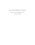
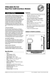
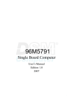
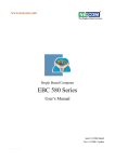
Jaemi Hubo (KHR4) Users Manual Daniel M. Lofaro October 7, 2009 1 1 Overview Welcome to the Hubo KHR4 reference manual. Through out this manual you will find information regarding the mechanical, electrical, and software operation of the Hubo KHR4 system. 1.1 Mechanical The Hubo KHR4 has the following mechanical specifications: Page 15 • 6 DOF Per Leg • 41 DOF Total • Aluminum Frame • High Gear Ratio Harmonic Drive Gear Boxes • Maxon Brushless DC Motors The gear ratios for the harmonic drive gear boxes can be found in Table 1. Table 1: Harmonic Drive Gear Ratios Joint Harmonic Drive No Hip Yaw SHD 17 - 100:1 Hip Roll SHD 20 - 160:1 Hip Pitch SHD 20 - 160:1 Knee SHD 20 - 160:1 Ankle Pitch SHD 17 - 100:1 Ankle Roll SHD 17 - 100:1 Trunk Yaw SHD 14 - 100:1 Please refer to Appendix A.1 for the dimensions of the Hubo HKR4. 1.2 Electrical Hubo KHR4 contains two primary x86 based computers, denoted as the Head Computer and the Body Computer, and multiple smart motor controllers. The Body Computer tells all of the motor controllers where to move 2 Figure 1: Hubo KHR4 Joint Direction 3 via communication over two 1MB/s CAN Buses, gathers sensor data from the Inertial Measurement Unit (IMU) and Force-Torque (FT) sensors. The Body Computer will then do all of the calculations to keep the Hubo KHR4 balanced properly. 1.2.1 Main Computers Table 2 contains some of the specifications for the Hubo KHR4 Body Computer. Further Specifications can be found in Appendix A.3. Table 2: Hubo HKR4 Body Computer Specifications Name PCM-3370 CPU Pentium III 933MHz Cache 512Kb Chip Set TwisterT + VT82C686B BIOS AWARD 256kb Flash BIOS System Memory 512MB SDRAM Watchdog Timer 1.6sec Expantion 104-pin PC/104 and 120-pin PCI PC/104-Plus Table 3 contains some of the specifications for the Hubo KHR4 Head Computer. Further Specifications can be found in Appendix A.2. Table 3: Hubo HKR4 Head Computer Specifications Name PCM-3372 CPU Pentium III 1.0GHz Cache 128Kb Chip Set VIA CX700 BIOS AWARD 4Mbit Flash BIOS System Memory 1024Mb DD2533 Watchdog Timer 255 levels interval timer Expantion 104-pin PC/104 and 120-pin PCI PC/104-Plus 4 1.2.2 Motor Controllers The Hubo KHR4 motor controllers consists of three separate motor controllers. • Single Channel Motor Controller/Driver • Dual Channel Motor Controller/Driver • Five Channel Motor Controller/Driver Each of the motor drivers have the same basic firmware on them and take the same basic command however the single channel controller only supports a single motor with quadrature encoder and is used only for the waste. The dual channel supports two motors with quadrature encoders (2x200W) and is used for all of the leg joints and some of the upper body joints. The five channel supports five smaller motors each with a quadrature encoder which is used for the fingers on the right and left hands. All of the motor controllers support current feedback. 1.3 Software Hubo KHR4’s Body Computer and Head Computer both run full versions of Windows XP updated to Service Pack 2. WARNING: Both systems must NOT be updated to Service Pack 3 for the time being due to the Wireless N drivers incompatibility with Service Pack 3. 1.3.1 Body Computer The Body Computer’s main operating system is Windows XP SP2 and the control is compiled using Visual Studios 6 (VS6) and Real Time Extensions 6.5 (RTX 6.5) by Ardence. The RTX system will be explained in greater detail in Section 3.1. The purpose of the Body Computer is to give Hubo KHR4 a dedicated environment for its balancing controller. The Body Computer does not have any .NET framework installed. 1.3.2 Head Computer The Head Computer’s main operating system is Windows XP SP2. The .NET framework 3.5 is currently installed. The purpose of this is so users 5 programing with Microsoft’s Visual Studio 2008 can easily upload custom software. The purpose of the Head Computer is to allow users to add human interaction without risking damaging the stability controller, i.e. the Body Computer. 6 2 Communication The Hubo KHR4 has multiple communication methods. In short the Body Computer communicates with the motor drivers via two 1Mbps CAN Bus networks. The Body Computer can talk to the Head Computer via a serial RS232 level signal. Both of the Body and Head Computers talk to the Base Station Computer via a wireless 802.11n network connection. 2.1 Base Station Computer The Base Station Computer connects to the Body and Head Computers via a Wireless 802.11n connection where the Base Station Computer is connected to the wireless router via a CAT-5e cable the Body and Head Computers are connected to the network via the 802.11n connection. The Base Station Computer also acts as the network storage device for both the Body and Head Computers. The ”Shared Documents” folder on the Base Station Computer is setup as the Z: drive on both the Body and Head Computers. 2.2 Body Computer The Body Computer is the main computer for the Hubo KHR4. This computer communicates with all of the motor drivers via two 1Mbps CAN Buses. All of the lower body joints are located on one CAN Bus and all of the upper body joints are located on the other CAN Bus. The Body Computer is a PCM-3370 PC/104 computer. More information on the PCM-3370 can be found in Appendix A.3. All of the communication methods available on the Body Computer can be found in Table 4. 2.2.1 CAN Bus The CAN Bus is a PCM-3680 Rev A.1 PC/104 Dual Port CAN Interface Module. Information regarding the PCM-3780 Rev A.1 CAN card can be found in Table 5 and in Appendix A.4. 2.2.2 RS232 The Body Computer contains two serial ports, COM1 and COM2. COM1 and COM2 are by default both connected to the Head Computer through 7 Table 4: Hubo KHR4 Body Number of Ports 2x 1x 1x 1x 1x 1x 1x 2x Computer On Board Communication Port Type USB1.1 EIDE LPT RS-232/422/485 (COM1) RS232 (COM2) K/B Mouse CAN internal connections. 2.2.3 Wireless The Body Computer communicates with the Hubo network, called HuNet, via an 802.11n connection. The wireless configuration for the Body Computer can be found in Table 6. 2.2.4 Wired The Body Computer can be plugged directly in to a 10/100 network and accessed. The Body Computer has a Static IP so it can be connected to via a network hub or directly via a crossover cable. The connection information can be found in Table ??. 2.2.5 2.3 Digital I/O Head Computer 2.3.1 RS232 2.3.2 Wireless 2.3.3 Wired The Head Computer can be plugged directly in to a 10/100 network and accessed. The Head Computer has a Static IP so it can be connected to via 8 Table 5: PCM-3680 Rev A.1 PC/104 CAN Card Specifications Ports 2 CAN controller 82C200 CAN transceiver 82C250 Signal support CAN-L, CAN-H Memory address From C800H to EF00H IRQ 3, 4, 5, 6, 7, 9, 10, 11, 12, 15 Isolation voltage 1000 VDC Power consumption +5 V @ 400 mA typical, 950 mA max. Connectors Dual DB-9 male connectors Operating temperature 32 to 122 F (0 to 50 C) PC/104 form factor 3.6” x 3.8” (90 mm x 96 mm) Shipping weight 0.9 lb (0.4 kg) a network hub or directly via a crossover cable. The connection information can be found in Table ??. 2.3.4 Digital I/O 9 Table 6: Body Computer SSID Frequency Standard WPA2 Passkey IP Mask Gateway Domain Wireless Configuration HuNet 2.4Ghz 802.11n dasl1234 192.168.0.102 255.255.255.0 192.168.0.1 Hunet Table 7: Body Computer Wired Configuration Network HuNet Standard 10/100 IP (Static) 192.168.0.112 Mask 255.255.255.0 Gateway 192.168.0.1 Domain Hunet Table 8: Head Computer SSID Frequency Standard WPA2 Passkey IP Mask Gateway Domain 10 Wireless Configuration HuNet 2.4Ghz 802.11n dasl1234 192.168.0.103 255.255.255.0 192.168.0.1 Hunet Table 9: Head Computer Wired Configuration Network HuNet Standard 10/100 IP (Static) 192.168.0.113 Mask 255.255.255.0 Gateway 192.168.0.1 Domain Hunet 11 3 Timing 3.1 RTX 3.2 Body Computer 3.2.1 Hardware 3.2.2 Software 3.3 Head Computer 3.3.1 Hardware 3.3.2 Software 12 4 Sensors 4.1 IMU 4.2 Force-Torque 4.3 Encoders 4.4 Current Sensing 5 Motor Drivers 6 How To 6.1 Upper Body Example: Raise Arm 6.2 Lower Body Example: Raise Leg 13 A Appendix 14 A.1 Hubo KHR4 Dimensions 15 4 3 1 181.87 214.50 D 181.59 289.47 107.00 179.14 230.00 120.00 88.43 79.50 303.87 D 2 C 300.03 C B 94.97 300.38 B 130.00 220.00 DRAWN RJG 9/23/2009 Drexel Autonomous Systems Lab CHECKED TITLE QA A MFG A JAEMI HUBO DIMENSIONS APPROVED SIZE C SCALE 4 3 2 REV DWG NO HUBO KHR-4 Rev_01 SHEET 1 1 OF 1 A.2 Head Computer Specifications 17 PCM-3370 36-bit TFT LV Intel® Pentium® III PC/104-Plus CPU Module Features PC/104+ ULV Intel® Celeron® 400/650 MHz Fanless, LV Pentium® III 800/933 MHz Inverter Power Chipset: VIA® VT8606/TwisterT and VT82C686B Fan IR VGA/LCD controller with optimized Shared Memory Architecture (SMA) LAN 4 x AGP VGA/LCD & LCD controller up to 1024 x 768 422/485 CRT USB IDE +5 V and +12 V power supply required 10/100Mbps PCI Ethernet interface, supports wake-on-LAN COM2 (5 V) supports power line connected on pin 9 COM2 LPT PC/104 and PC/104-Plus expansion connector Power Support for CompactFlash® Card (CFC) Type I Socket COM1 1.6 sec – interval Watchdog timer PC/104 KB/Mouse 1 SODIMM socket supports up to 512 MB SDRAM ATX Standby power Specifications Mechanical and Environmental General CPU 2nd Cache Memory System Chipset BIOS System Memory Power Management SSD Watchdog Timer Expansion Interface Onboard ULV Intel Celeron 400/650 MHz Fanless, or LV Pentium III 933 (800 MHz optional) 256 KB on ULV Celeron/512 KB on Pentium III VIA VT8606/TwiserT + VT82C686B AWARD® 256 KB Flash BIOS 1 x SODIMM socket, supports up to 512 MB SDRAM Supports Advanced Power Management Supports CompactFlash Card Type I 1.6 sec – interval Watchdog timer, set up by software, jumperless selection, generates system reset or IRQ11 104-pin 16-bit PC/104 module connector and 120-pin PCI PC/104-Plus module connector I/O I/O Interface USB IrDA I/O Expansion 1 x EIDE, 1 x LPT, 1 x RS-232/422/485, 1 x RS232, 1 x K/B, 1 x Mouse 2 Universal Serial Bus 1.1 compliant ports Share with COM2, transfer rate up to 1.15 Mbps Support for + 5 V FAN, speed detect connector, Heat, Fan speed Ethernet Chipset Speed Interface Realtek RTL8139D 10/100 Mbps 10/100Base-T 1 x RJ-45 Display Chipset *VIA VT8606 4X AGP controller, supporting CRT PCM-3370F: 18/24/36 bit TTL interface PCM-3370E: 18/24 bit TTL interface and 36 bit dual channel LVDS Dimension (L x W) Weight Operating Temperature Operating Humidity 96 x 115 mm 0.162 kg (with heat sink) 0 ~ 60° C 0% ~ 90% relative humidity, non-condensing Power Power Supply Voltage +5 V ±5%, +12 V ±5% Power Consumption Typical: 2.43 A @ +5 V (ULV Celeron 400 MHz CPU) 2.83 A @ +5 V (ULV Celeron 650 MHz CPU) 3.50 A @ +5 V (LV Pentium III 933 MHz CPU) 0.02 A @ +12 V (ULV Celeron 400 MHz CPU) 0.02 A @ +12 V (ULV Celeron 650 MHz CPU) 0.02 A @ +12 V (LV Pentium III 933 MHz CPU) Max: 2.47 A @ +5 V (ULV Celeron 400 MHz CPU) 2.97 A @ +5 V (ULV Celeron 650 MHz CPU) 3.99 A @ +5 V (LV Pentium III 933 MHz CPU) 0.06 A @ +12 V (ULV Celeron 400 MHz CPU) 0.06 A @ +12 V (ULV Celeron 650 MHz CPU) 0.08 A @ +12 V (LV Pentium III 933 MHz CPU) Packing List 1 x PCM-3370 SBC 1 x KB/Mouse Y-Cable 1 x Y-Cable external cable 1 x VGA Cable 1 x Ethernet RJ-45 Conn. conversion cable 1 x IDE Cable 1 x COM Port Cable 1 x LPT port cable 1 x Wire ATX Power 1 x Startup manual 1 x CD-ROM (Manual, Driver, Utility) (p/n:1700060202) (p/n:1703060053) (p/n:1701160150) (p/n:1701100202) (p/n:1701440350) (p/n:1700100250) (p/n:1700260250) (p/n:1703200380) Online Download www.advantech.com/products All product specifications are subject to change without notice Last updated : 20-Mar-2006 PCM-3370 Board Diagram Intel ULV/LV Processor VGA Connector VIA VT8606 TTL Panel Connector SDRAM SODIMM IDE PC-104 connector PCI Bus COM VIA VT82C686B COM CF ISA LAN Connector USB 1.1 KB/MS PC/104 connector LPT Audio Ordering Information Part No. PCM-3370F-R0A1E PCM-3370F-M0A1E PCM-3370F-J0A1E PCM-3370Z-J0A1E PCM-3370Z1-J0A1E PCM-3370E-R0A1E PCM-3370E-M0A1E PCM-3370E-J0A1E CPU LV Pentium III 933 Mhz ULV Celeron 650 Mhz ULV Celeron 400 Mhz ULV Celeron 400 Mhz ULV Celeron 400 Mhz LV Pentium III 933 Mhz ULV Celeron 650 Mhz ULV Celeron 400 Mhz L2 Chipset Cache VIA8606+ 256 KB 686B VIA8606+ 256 KB 686B VIA8606+ 256 KB 686B VIA8606+ 256 KB 686B VIA8606+ 256 KB 686B VIA8606+ 256 KB 686B VIA8606+ 256 KB 686B VIA8606+ 256 KB 686B CRT LVDS TTL 10/100 Yes -- 36 bit 1 2 2 *Option Yes Yes Yes Yes Yes Active 0 ~ 60°C Yes -- 36 bit 1 2 2 *Option Yes Yes Yes Yes Yes Passive 0 ~ 60°C Yes -- 36 bit 1 2 2 *Option Yes Yes Yes Yes Yes Passive 0 ~ 60°C Yes -- 36 bit 1 2 2 *Option Yes Yes Yes Yes Yes Passive -20 ~ 80°C Yes -- 36 bit 1 2 2 *Option Yes Yes Yes Yes Yes Passive -30 ~ 70°C Yes 36 bit 24 bit 1 2 2 *Option Yes Yes Yes Yes Yes Active 0 ~ 60°C Yes 36 bit 24 bit 1 2 2 *Option Yes Yes Yes Yes Yes Passive 0 ~ 60°C Yes 36 bit 24 bit 1 2 2 *Option Yes Yes Yes Yes Yes Passive 0 ~ 60°C Optional Accessories RS-422/485 cable 12cm USB cable 26cm USB cable (p/n:1703040257) (p/n:1703100121) (p/n:1703100261) PC/104 Modules Thermal Operation USB PCI-104 PC/104 RS-232 RS-422/485 LPT CF KB/MS 1.1 connector connector Solution Temp. A.3 Body Computer Specifications 20 PCM-3372 NEW VIA Eden™ (V4) + CX700 PC/104-Plus CPU Module Features PS_ON -5/-12 input Reset Clear CMOS ATX Power FAN Power USB1-6 VIA Eden™ (V4) 400/600 MHz and ULV1.0 GHz processor; VIA C7 2.0 GHz processor KB/MS Supports DDR2 memory CF LVDS-I LVDS-E COM1-2 Supports 10/100 Base-T Ethernet IDE 48-bit TFT LCD LVDS interface Audio Supports one RS-232, one RS-232/422/485, and six USB 2.0 ports LAN PC/104 and PC/104-Plus expansion connector Support audio function compliant with HD SA1 SA2 RS-422/485 Inverter-E Inverter-I LVDS-E Power SEL LVDS-I Power SEL PCI VIO Sel DIO Support for CompactFlash® card type I 422/485 SEL Specifications Mechanical and Environmental General CPU 2nd Cache Memory System Chipset BIOS System Memory Power Management SSD Watchdog Timer Expansion Interface Battery VIA Eden (V4) processor for 400/600 MHz and ULV1.0 GHz; VIA C7 2.0 GHz processor 128 KB on Processor VIA CX700 AWARD® 4 Mbit Flash BIOS 200-pin SODIMM socket, supports DDR2 SDRAM, to 128/256/512/1024Mb. DDR2 533/400 SDRAM ACPI supported, APM1.2 Supports CompactFlash Card Type I 255 levels interval timer, setup by software. 104-pin 16-bit PC/104 module connector and 120-pin PCI PC/104-Plus module connector Lithium 3 V/196 mAH I/O I/O Interface USB Audio GPIO 1 x EIDE, 1 x RS-232/422/485, 1 x RS232, 1 x K/B, 1 x Mouse. 2 x SATA 6 x USB 2.0 Supports HD Audio stereo sound 8-bit general purpose (4 Input/4 Output) Ethernet Chipset Speed Interface Intel 82551ER 10/100Base-T 1 x internal box header Display Chipset Memory Size Resolution Dimension (L x W) Weight Operating Temperature Operating Humidity 96 mm x 115 mm 0.162 kg (with heat sink) 0 ~ 60° C (32 ~ 140° F) 0% ~ 90% relative humidity, non-condensing Power Power Supply Voltage AT/ATX, +5 V ± 5%, +12 V ± 5% (Optional) (5 V only, 12 V optional for PC104 add on card and LCD inverter) Power Consumption Typical: +5 V 1.45 A +12 V 0.02 A MAX: +5 V 2.63 A +12 V 0.03 A (Eden ULV1.0GHz with 512M RAM) Packing List 1 x PCM-3372 SBC 1 x Wire AT Power cable 1 x Audio cable 1 x Wire ATX power 1 x Two COM cable 1 x RS-422/485 COM cable 1 x Keyboard/Mouse cable 1 x Y cable (for KB/MS extention) 1 x Ethernet RJ-45 Conn. conversion cable 1 x IDE cable 1 x VGA cable 1 x USB cable (bracket type with two USB ports) 1 x SATA cable 1 x Startup manual 1 x CD-ROM (Manual, Driver, Utility) (p/n:1703080104) (p/n:1703100152) (p/n:1703200380) (p/n:1701200180) (p/n:1703040157) (p/n:1703060053) (p/n:1700060202) (p/n:1701100202) (p/n:1701440350) (p/n:1700000898) (p/n:17000000897) (p/n:1700071000) VIA CX700 Optimized Shared Memory Architecture, supports 64 MB frame buffer using system memory CRT display Mode pixel resolution up to 1920 x 1440 x 32 bpp at 85 Hz 1600 x 1200 x 16 bpp at 100 Hz and, up to 1024 x 768 x 32 bpp at 60 Hz for TFT LCD LCD Interface 24/48 bit LVDS interface Dual Independent Display CRT + LVDS, LVDS+LVDS (optional) Online Download www.advantech.com/products All product specifications are subject to change without notice Last updated : 7-Feb-2007 PCM-3372 Board Diagram IMVP4.0 EDEN V4 PG3,4 LVDS Channel LVDS BUS FSB PG10 Strapping SW PG30 400/533 PG18 DDR2 SODIMM x1PG11,12 DDR400 / DDR533 LVDS Connector PG17 Transmitter VT1636 PG26~28 Clock Gen D VO( D VP1) 10/100/1000 LAN Intel 82551ER RJ-45 PG21 PG17 Frequenc y Analog CRT GPIO PG13 PG22 PCI BUS SMBus PCA9554 PG13 6 USB Port CX700 PCI to ISA Bridge IT888G PG19 PC104+ Connector PG19,20 PG22 LPC PG5~9 1 EIDE Channel PG15 Super I/O (I) SMSC3114 BIOS PG14 On board Flash PG16 PG13 COM1~2 PG24 LPT PG25 PS/2 KB/MS PG23 HW Monitoring PG13 2 SATA Port PG8 Ordering Information Part No. CPU VIA Eden (V4) 400 MHz VIA Eden (V4) PCM-3372F-M0A1E 600 MHz VIA Eden (V4) PCM-3372F-S0A1E ULV 1.0 GHz U0A1E VIA PCM-3372F-U0A1E C7 2.0GHz PCM-3372F-J0A1E Chipset L2 Cache CRT TTL LVDS 10/100 USB2.0 RS-232 RS-232/ 422/485 LPT/KB/ MS SATA CF CX700 128 KB Yes -- 48-bit 1 6 1 1 Yes 2 Yes Yes Yes Passive 0 ~ 60° C optional CX700 128 KB Yes -- 48-bit 1 6 1 1 Yes 2 Yes Yes Yes Passive 0 ~ 60° C optional CX700 128 KB Yes -- 48-bit 1 6 1 1 Yes 2 Yes Yes Yes Passive 0 ~ 60° C optional CX700 128 KB Yes -- 48-bit 1 6 1 1 Yes 2 Yes Yes Yes Passive 0 ~ 60° C optional Stackable SBCs Audio PC/104+ Thermal Operation Embedded connector Solution Temp. OS A.4 CAN Card Specifications 23 E S 4 L E EM B PC 0 /1 M O DU • Operates 2 separate CAN networks at the same time • High speed transmission up to 1 Mbps • 16 MHz CAN controller frequency • Takes a 4 KB address space, 40 base address adjustable in steps from C800H up to EF00H • Optical isolation protection of 1000 VDC ensures system reliability • Wide IRQ selection for each port includes: IRQ 3, 4, 5, 6,7, 9, 10, 11, 12, 15 • LED indicates Transmit/Receive status on each port • Direct memory mapping enables speedy access to the CAN controllers • C library and examples included Control Area Network Jumper & Switch Locations Ports: 2 • CAN controller: 82C200 • CAN transceiver: 82C250 • Signal support: CAN-L, CAN-H • Memory address: From C800H to EF00H • IRQ: 3, 4, 5, 6, 7, 9, 10, 11, 12, 15 • Isolation voltage: 1000 VDC • Power consumption: +5 V @ 400 mA typical, 950 mA max. • Connectors: Dual DB-9 male connectors • Operating temperature: 32 to 122° F (0 to 50° C) • PC/104 form factor: 3.6" x 3.8" (90 mm x 96 mm) • Shipping weight: 0.9 lb (0.4 kg) PCM-3680 User's Manual PC/104 and the PC/104 logo are trademarks of the PC/104 Consortium JP6 TR2 On-board optical isolators protect your PC and equipment against damage from ground loops, increasing system reliability in harsh environments. • CH#2 3 4 5 6 7 9 10 11 12 15 Optical Isolation Protection Specifications CH#1 TR1 DIPSW IRQ JP5 A17 A16 A15 The PCM-3680 is assigned with memory address, which allows direct access to the CAN controller. This is the simplest and fastest way of programming any board in a PC because the board is regarded as standard RAM. A14 A13 A12 Direct Memory Mapping RX1 TX2 RX2 CH#1 TX1 CH#1 The CAN (Control Area Network) is a serial bus system especially suited for networking "intelligent" I/O devices as well as sensors and actuators within a machine or plant. Characterized by its multi-master protocol, real-time capability, error correction, high noise immunity, and the existence of many different silicon components, the CAN serial bus system, originally developed by Bosch for use in automobiles, is increasingly being used in industrial automation. CH#2 The PCM-3680 is a special purpose communication card that brings the Control Area Network to your PC. With the built-in CAN controller, the PCM-3680 provides bus arbitration and error detection with automatic transmission repeat function. This drastically avoids data loss and ensures system reliability. The on-board CAN controllers are located at different positions in the memory. You can run both CAN controllers at the same time, independently. The PCM-3680 operates at baud rates up to 1 Mbps and can be installed directly into the expansion slot of your PC. Features CH#2 IJumper Settingntroduction B1 A1 PCM-3680 PC/104 Dual Port CAN Interface Module PCM-3680 PC/104 Dual Port CAN Interface Module ED-PC DD B32 A32 C20 D20 C1 D1 PCM-3680 REV. A1 1 Part no. 2000368000 1st Edition Printed in Taiwan May 1996