Transcript
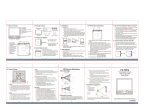
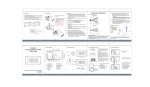
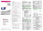
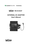
Setting
Name and Parts
Removing the front case
1. Power switch
2. USB port
3. MicroSD card slot
4. VGA/HD switch
5. Record/Photo switch
6. Power LED
7. Record/Photo LED
8. Charge LED
9. Microphone
10. Camera
11. PIR sensor
5
4
11
Place the unit on a flat surface with the PIR sensor
facing upwards. Place your fingers on top and
bottom edge of the unit, with another hand to gently
press the fake switch to remove the front case from
the device.
Charging the battery
3
2
10
9
1
7
6
8
Package Content
USB cable
European adapter
Regular charging
1. Connect the charger to a wall outlet.
2. Connect the charger to the device. When
the battery is fully charged the green indicator
goes out.
MicroSD card (4GB)
Double-side tape
USB charging
You can use USB charging when a wall outlet
is not available.
1. Connect a compatible USB device to
the DVR using the supplied USB cable.
2. The green indicator lights on when the
device is being charged and goes out
when battery is fully charged.
Insert the memory card
Format the memory card
PIR Sensor Illustration
X
5m
16.404ft
00
190
2m
5.562ft
0
110
2.5
8.202
2.5m
8.202ft
5m
16.404ft
00
110
1.25
4.101
2m
5.562ft
Wall Switch DVR
Quick Guide
<2>Cases where it is difficult to detect the heat source.
(1) When an object made of glass acrylic or other subject which far
infrared rays have difficult passing through is located between
the sensor and what is to be detected.
3.Installation Suggestion
Y
1.25
4.101
DVR253
(2) When the heat source inside the detection range hardly moves or
when is moves at high speed.
5m
16.404ft
SIDE VIEW
2.5
8.202
(1) When a small animal enters the detection range.
(3) When the temperature inside the detection range has changed
suddenly due to the entry of cold or warm air from an
air-conditioning or heating unit, water vapor from a humidifier, etc.
190
1.25
4.101
2.5m
8.202ft
<1>Cases where a heat source other than a human being is detected
(2) When the sensor is directly exposed to sunlight, a vehicle’s
headlights, an incandescent light or some other source or far
infrared rays.
TOP VIEW
1.25
4.101
(3)
(2)
1.Detection Range
2.5
8.202
Retrieving video footage from DVR
1. Video file is stored in the memory card.
2. There are two methods to retrieve video files.
2.1 Using USB cable to connect to computer.
2.2 Using memory card reader to read and write folder directory
3. Computer detects the storage and user may browse and
operate the storage as typical folder directory.
1. Press and hold the round shape format button
then power on the device.
2. The red indicator will flash when the memory card
is being formatted. The red light will go out when
memory card format completed.
(1)
0
Installation
1. Clean the backside surface of the device before applying
the double-side adhesive tape.
2. Clean the area of the wall you intend to install the device, peel
the film from double-side adhesive tape on the device
then pasting the device onto the wall.
3. Under standby status the battery can last
about 5-6 days.
1. Insert a compatible memory card in the slot.
Ensure that the contact area on the card is facing
down and towards the slot.
2. Push the card in. You can hear a click when the
card locks into place.
Charger
2.5
8.202
1. Select operation mode by sliding Photo/Rec switch to place.
1.1 Video: Whenever the PIR sensor is triggered, the DVR automatically
starts recording. Please note the length of video varies from 5 seconds
to 2 minutes depending on the movement detection.
1.2 Photo: The device takes 3 photos whenever the PIR sensor is triggered.
2. Resolution setting by sliding VGA/HD switch to place.
2.1 Video resolution: VGA(640X480@30fps)
HD(1280X720@30fps)
2.2 Photo resolution: 2MP (1600X1200 .JPG)
3. LED indicator
3.1 Blue(Power): Blue indicator lights on when the device is powered on.
3.2 Red(Rec): Red indicator lights on when recording video or taking photo.
3.3 Green(Charge): Green indicator lights on when charging and goes out
when battery is fully charged.
5m
16.404ft
Definition:
O - the height of object
H - the height of sensor
from the ground
D - the distance between
object and sensor
Formula:
H-O/2
D-Ox2
180CM
H
2.Detection concerns
They may fail to detect successfully if a heat source other than a human
being is detected or if there are no temperature changes in or movement of
a heat source. Care must generally be taken in the following cases.
The performance and reliability of the sensors must be checked out under
conditions of actual use.
(4)
O
90CM
3.6M
D
For example: To film a man at 180cm height in the video, the sensor
should be placed at 90cm height above the ground and the man is 3.6m
away from the sensor.
(5)
Law Enforcement Product Manufacturer
V1.0