1
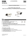
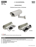
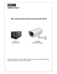
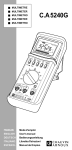
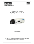
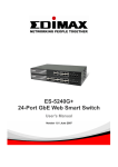
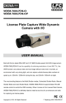
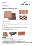
Please read the Operational Manual before attempting to use this product. Operational Manual Super Power IR LED Illuminator & Professional Camera Housing HI7-TKHBL FEATURES 7 IR LED 7 Super Power IR LED, 4pc x 25o / 3pc x 45o IR Distance up to 250ft / 80m IP66 Rating User Adjustable IR LED Intensity (VR), Factory Default 80% Fully-Cable Managed Mounting Bracket Uses professional rust-proof stainless steel screws Heater & Blower 24V AC, 60VA, Power Ready Plug for 12V DC Camera HI11-TKHBL FEATURES 11 IR LED 11 Super Power IR LED, 6pc x 25o / 5pc x 45o IR Distance up to 395ft / 120m IP66 Rating User Adjustable IR LED Intensity (VR), Factory Default 80% Fully-Cable Managed Bracket Uses professional rust-proof stainless steel screws Heater & Blower 24V AC, 60VA, Power Ready Plug for 12V DC Camera * UL certification only refers to the power converter and the power module Please see page 6 1 HI7-TKHBL_HI11-TKHBL_rev042709 PART DESCRIPTION 2 HI7-TKHBL_HI11-TKHBL_rev042709 1. Lens Cap with Heater 2. Temper Glass 3. IR LED: 7pcs or 11pcs Super Power IR LED with Refractor 4. IR Board and IR Board Bracket 5. Universal IR Control Circuit Board: When the IR light turns on, it automatically adjusts the color to monochromatic through the universal IR control circuit. 6. Camera Bracket 7. Power Supply Unit: 24V AC input, 60VA 8. Blower and Blower Bracket 9. Thermostat Switch 10. Video Input BNC Male Connector: Connect to camera 11. Video Out BNC Female Connector: Connect to monitor 12. Terminal Board 13. Fuse Holder: With 250V / 3.15A fuse 14. AC IN Terminal block: 24V AC external power input 15. OUTPUT_1 Terminal block: Plug and fix the power cable of camera 16. OUTPUT_2 Terminal block: To power supply unit 17. VR: Adjust VR to set Infrared LED activation level Factory default 80% -- If there is not enough IR light, adjust the level to maximum 100% 18. Thermostat Switch: Turns on at 35C / 95F and turns off at 25C / 77F for Blower 19. Ground wire: To top cover 20. 12V DC Power-in jack: To camera / center+, outerWhen using a camera which requires a 24V AC power input, please run a separate power line to the camera 21. Flying Bare Lead Wire: When the wire is not in use, cover it with the screw-on connector or tape the tip with tape to prevent damages caused by the bare lead wire. 3 HI7-TKHBL_HI11-TKHBL_rev042709 INSTALLATION 1. 2. 3. 4. Loosen two screws on both sides of the camera bracket first. Use the provided screw to fix the camera (not included) on the camera bracket. Adjust zoom, focus and iris of the lens on the camera. Adjust the direction of the camera for proper position, after finished tighten all screws. How to install cables through the mounting bracket: 4 HI7-TKHBL_HI11-TKHBL_rev042709 EXTERNAL POWER INPUT CONNECTION NOTE: When using two-cord power cable, please connect them to “Live” and “Neutral.” DIMENSIONS (mm) HI7-TKHBL / HI11-TKHBL: Fully-Cable Managed Bracket: Max Load: 3500g Material: Die-cast aluminum alloy with light ivory powder coated and stove finish Scan Angle: 180° Tilt Angle: 90° Net Weight: 900g Fixing: 3 Screws with bushings 5 HI7-TKHBL_HI11-TKHBL_rev042709 GENERAL SPECIFICATIONS Model LED Quantity IR LED Beam Angle IR Wave Length IR Distance IR Light On/Off Heater Control Blower Control IP Rating Temper Glass Thickness Mounting Bracket Construction Coating Required Power Supply / Transformer * Power Consumption Dimension Camera Space Weight HI7-TKHBL 7 Super Power IR LEDs 4pc x 25o / 3pc x 45o HI11-TKHBL 11 Super Power IR LEDs 6pc x 25o / 5pc x 45o 850nm 250ft / 80m 395ft / 120m Auto Light Sensor Control 18C / 64F (on); 28C / 82F (off) 35C / 95F (on); 25C / 77F (off) IP66 4mm Full-Cable Management Die-Cast Aluminum Alloy Ivory Powder Stove 24V AC (+/-10%), 60VA 9 Watts 16 Watts 16.73”(L) x 6.30”(W) x 6.50”(H) / 425mm(L) x 160mm(W) x 165mm(H) 7.87”(L) x 4.33”(W) x 4.53”(H) / 200mm(L) x 110mm(W) x 115mm(H) 7.72 lbs / 3500g (w/out bracket) 7.72 lbs / 3500g (w/out bracket) 11.55 lbs / 5240g (with bracket) 11.75 lbs / 5330g (with bracket) * Power supply / transformer not included NOTE 1: IR light distances are entirely dependant upon environmental site conditions and the location at which the unit is situated. The type of camera being used is also very important. NOTE 2: Factory default for the IR LED activation level is 80%. If there is not enough IR light, adjust the VR level to maximum 100%. Please see #17 in the Part Description section on page 1. PACKAGE CONTENTS One One One One One (1) HI7-TKHBL or HI11-TKHBL IR Illuminator & Professional Camera Housing (1) Fully-Cable Managed Bracket (1) Operational Manual (1) Main Accessories Pack Three (3) Rust-proof Stainless Steel Wall Screws Three (3) Rust-proof Stainless Steel Mounting Screws Three (3) Stainless Steel Washers Three (3) Plastic Washers One (1) Allen Wrench (1) Secondary Accessories Pack Three (3) Screw-on Connectors One (1) Rubber Pad One (1) Rust-proof Stainless Steel Camera Screw One (1) Plastic Washer * For any returns, please include all components listed above with original packaging in Resalable Condition. Absolutely No Returns will be accepted if any component is missing/damaged or if any cable is cut or tampered with. 6 HI7-TKHBL_HI11-TKHBL_rev042709 WARRANTY OKINA USA Products are covered under warranty for one year from the date of purchase. The warranty will automatically be voided if any of the following occurs: 1. Product sticker is removed If the product sticker is removed, we will not be able to confirm any information regarding when and where the product was purchased. We have no other way to verify the purchase record without the serial number on the product sticker; therefore, it should not be removed. 2. Product is modified in any way If the product is scratched, damaged, or modified in a manner not described in this manual, the warranty will be voided immediately. It is the customer’s responsibility to keep the product in good condition. 3. Power cable is cut The power cable and any other cable should not be tampered with. Cutting or modifying of the cables will result in termination of the warranty. IMPORTANT NOTE 1. Read and follow instructions All operating and user instructions should be read and followed before the unit is to be operated. 2. Secure all screws Please make sure all rust-proof stainless steel screws are installed securely to ensure a waterproof seal. 3. Electrical connections Only a qualified electrician should be allowed to make electrical connections. 4. Do not disassemble the product Do not disassemble the product as it is dangerous and may cause damage to the product. Refer all servicing to qualified service personnel. 5. Handle the product with care Be careful when handling the product. Do not drop it or subject it to strong shock or vibrations in order to prevent any damage to the product. Do not handle the product in a wet environment or when your hands are wet. 6. Reducing risk To reduce risk of fire or electric shock, do not remove cover. Do not open product in wet weather. No user serviceable parts inside. Refer servicing to qualified service personnel. 7. Unpacking Unpack carefully. Electronic components can be damaged if improperly handled or dropped. If an item appears to have been damaged during shipment, please place it properly in its carton and notify the shipper. 8. Installation notice Tropical, coastal salt water environment: If you plan to install this product into a tropical, sea, coastal salt water or corrosive industrial water/mist environment, please seal each stainless screw and fitting with a silicon grease compound. This will help prevent electrolysis corrosion occurring and extend the lifespan of the product and housing and prevent premature deterioration. 9. Voltage If you are using a camera which requires a 24V AC power input, please run a separate power line to the camera. 7 HI7-TKHBL_HI11-TKHBL_rev042709 8 HI7-TKHBL_HI11-TKHBL_rev042709