1
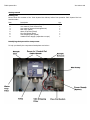
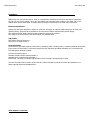
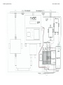
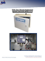
TVOC User Manual Supplement
System Plus User Guide V 1.1
TVOC System Plus
Ion Science Ltd
Declaration of Conformity
Manufacturer: Ion Science Ltd, The Way, Fowlmere, Cambridge, England. SG8 7UJ
Product: TVOC System Plus
Product description: Continuous Pumped Air System built around the Ion Science TVOC Product
Directive 2004/108EC
Electrical Equipment – Electromagnetic Compatibility (EMC)
BS EN 61326-1:2006
Electrical equipment for measurement, control and laboratory use – EMC
Requirements (Class B and General Immunity)
Other Standards
BS EN ISO 9001:2000
Quality Management Systems – Requirements
BS EN 61010-1:2001
Safety requirements for electrical equipment or measurement, control and
Laboratory use – General requirements
On behalf of Ion Science Ltd, I declare that, on the date this product accompanied by this declaration is placed on the
market, the product conforms to all technical and regulatory requirements of the above listed directives.
Name: Mark Stockdale
Signature:
Date: 28th May 2012
Position: Technical Director
TVOC System Plus
Contents
Frontpage
.
.
.
Declaration of conformity .
.
Contents
.
.
.
Principle of Operation
.
.
Quality Assurance .
.
.
Disposal
.
.
.
Responsibility for Use
.
.
Getting Started .
.
.
Packing List
.
.
.
System Plus Components Identification
Installation
.
.
.
Top-down overview
.
.
DIN Terminals
.
.
.
Service & Maintenance
.
.
Spare Parts
.
.
.
Maintenance
.
.
.
Ion Science Ltd
.
.
.
.
.
.
.
.
.
.
.
.
.
.
.
.
.
.
.
.
.
.
.
.
.
.
.
.
.
.
.
.
Page
1
2
3
4
4
4
4
5
5
5
6
7
8
9
9
10
TVOC System Plus
Ion Science Ltd
Principle of Operation
System Plus is an environmentally sealed (IP66) continuously pumped air system built around the Ion
Science TVOC product and can operate as a field portable or fixed operation system utilising different power
supply options to enhance the measurement capabilities of the TVOC Photo Ionisation Detector for
measuring VOC gases.
Gas flow in is connected to the Sample Inlet via a 6mm push fit connector, the integral Mini Pump,
working at a flow rate of 2 litres per minutes, draws the sample from the Sample Inlet, through a Water
Trap Filter, across the TVOC detectors’ sensor and through a Flow Fail Switch, the sampled gas then
exits the system via a VOC Stripping Filter to the Sample Exhaust.
Detected gas will be displayed on the TVOC’s LCD display and a measured output can be obtained via the
TVOC 4/20mA output (see TVOC manual for details). Also, as a safety precaution, any VOC gas passing
through the system will be absorbed into a VOC Stripping Filter before exiting the system via the Sample
Exhaust as clean air.
The System Plus option for TVOC is designed to be mounted in non-intrinsically safe areas only and allow a
gas sample to be drawn from a remote location up to a maximum of 30M away via 6mm PTFE tubing.
Ensure PTFE (or similar) sampling tubing is used so that any VOC’s are not absorbed into the tubing walls.
The 4-20mA analogue output is wired directly from the TVOC instrument to a DIN rail mounted connector
for ease of access for signal integration into a DCS for process control, BMS for warning alarms or used as a
data logging function. The System Plus box has multiple power input options (12V dc, 24V dc, 110/115V ac,
230/240V ac) allowing it to be utilised in both fixed and portable operations. Two additional cable glands are
provided on the top of the System Plus box to enable Power In and Control Out cabling.
PLEASE NOTE:
THIS MANUAL SHOULD BE READ IN CONJUNCTION WITH THE LATEST VERSION OF THE TVOC
INSTRUMENT MANUAL FOR INSTALLATION AND OPERATING PURPOSES:
Quality Assurance
System Plus has been designed in compliance with ISO9001:2008. This ensures that the equipment supplied
to our customers has been assembled reproducibly, and from traceable components.
Disposal
Dispose of the TVOC System+ and its components, in accordance with all local and national safety and
environmental requirements.
Responsibility For Use
The System Plus option for the TVOC instrument allows detection of a large range of Volatile Organic
Compound (VOC) gases which are dangerous from both a toxicological and explosive perspective. Ion
Science Ltd accepts no responsibility for the incorrect adjustment of features that cause harm or damage to
persons or property.
TVOC System Plus
Ion Science Ltd
Getting started
Packing List
Please check the contents of the TVOC System Plus delivery before first operation. Each System Plus box
should include:Item
1.
2.
3.
4.
5.
6.
7.
8.
Description
TVOC instrument complete (fitted)
User manual (TVOC Instrument)
User manual (System Plus Supplement)
Mini Pump (fitted)
Water Trap Filter (fitted)
Flow Fail Switch (fitted)
VOC Stripping Filter (fitted)
Variable Power Supply (Dependant on spec)
Identifying the System Plus Components
To help you identify the components listed please see below:-
Qty.
1
1
1
1
1
1
1
1
TVOC System Plus
Ion Science Ltd
Installation
System Plus can be wall mounted or used as a stand-alone instrument as all input and output connections
are via the top of the cabinet. There are pre-drilled wall mounting holes located in the back wall of the
cabinet which should have gland or stopper fitted if using the System Plus as a stand-alone instrument.
Electrical Installation
System Plus has been designed to work from a 24V DC 1A supply, an optional mains supply can be used (see
optional extras). Space has been provided on the din rail to install an optional mains power supply.
The external 24V DC supply must be fused at 1A before entering the cabinet.
The supply is connected to the internal terminals, see drawing below
24V power
24V positive terminal number 8
24V zero to terminal number 7
Flow Fail Switch
A flow switch is provided to detect a flow failure, caused by either a faulty pump or completely blocked inlet/outlet,
In the event of a flow failure, a fail relay operates the flow fail switch providing indication via a red led and volt
free changeover terminal contacts.
Common terminal number 1
Normally Closed Contact terminal number 2
Normally Open Contact terminal number 3
Please note. The relay is a failsafe type operation and is normally energised with no fault.
The flow fail switch can be used in series with the TVOC mA output to provide a remote fault indication or to
switch external visual and audible alarms.
TVOC System+ Overview
TVOC System Plus
Ion Science Ltd
TVOC System Plus
DIN Rail Terminations
Ion Science Ltd
TVOC System Plus
Ion Science Ltd
Service & Maintenance
Service Intervals
The TVOC instrument housed in the System Plus enclosure should be serviced in accordance with the guide
lines in the current TVOC Operating Manual.
Important note for service of the TVOC;
The TVOC is fitted with a surge detecting circuit which will blow the TVOC supply fuse when the TVOC’s supply is
connected with a fast DC rise time, as with an ON OFF switch, to prevent this problem it is advised to switch the
DC supply off from the mains supply, this will provide a slow rise of the DC when the mains supply is returned .
Service intervals for the System Plus components will depend mainly on the external factors affecting its
operation such as concentration of gas being sampled, moisture content of sampled gas, length of sample
line being used, etc., etc.
As a guide we would recommend the following Service and Maintenance program:
Weekly
Water Trap Filter - check and remove any water in the unit. To disassemble remove the tubing from either end
and remove the filter by pulling out of the spring clip, drain water and
Biannually
Lamp & Stack – Replace the TVOC lamp and stack.
Water Trap Filter - fit a new filter assembly
Annually
Mini Pump – replace with a new pump - the pump’s polarity should be observed, Positive wire to terminal
number 10, Negative wire to terminal number 6. The pump is fitted onto a spring clip.
It is important when fitting the flexible tubing to the pump to observe correct flow.
Water Trap Filter - fit a new filter assembly.
Lamp & Stack – Replace the TVOC lamp and stack.
VOC Stripping Filter - replace with a new filter. Replacement is simply removing the tubing from either end and
fitting a new one in place
Tubing
If tubing needs to be replaced (discoloured/contaminated) this can be cut to length and supplied accordingly.
Spare Parts List
Part
Mini Pump
Water Trap Filter
VOC Stripping Filter
Lamp and stack
Flow Fail Switch
PTFE Tubing (available
in 1 metre lengths)
Description
Pump 24V DC 31/Min Brey
Polycap 36TF Filter
Zeroing in-line Filter
Replacement PID Sensor & lamp
Flow Switch Range 1000 ml/min
PTFE tubing 6mm OD 4mmID
Order Number
150-175
600-101
150-173
1/EO-02
901-000
TUBE-06
TVOC System Plus
Ion Science Ltd
Maintenance
Flow Fail Switch
The flow switch is factory pre-set to fail at 200cc’s. This setting can be checked with a Multimeter using the SET
terminal on the flow switch which should give a reading of 2.6V at the 200cc rate. The SET terminal is marked ‘S’
on the drawing below and is located between the DC Supply terminals
The flow failure rate can be changed if required depending on
the circumstances of the sampling regime.
For example an adjusted reading of 3.5V will give an
approximate flow fail at 500cc’s..
When adjusting the flow fail rate the results should be verified
for accuracy with a calibrated air sampling pump.