1
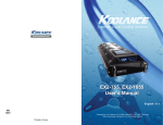
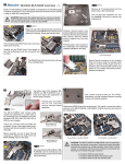
®
Superior Liquid Cooling Systems
www.koolance.com
ICM-PC30, ICM-PC54
User’s Manual
English v1.0
ISO
9001
Printed in Korea
This User Manual is updated regularly. Please be sure to check our support page for a newer
version of this guide: www.koolance.com
GENERAL PRECAUTION
Please read this manual carefully before beginning the installation of your Koolance system.
This manual assumes the user has basic experience in building and configuring computer
systems. Information referring to traditional hardware assembly is intentionally brief.
ABOUT SIGNS
Throughout this document, critical information is highlighted in gray-colored boxes. The
following symbols are intended to help prevent any situation which may cause personal
injury and/or damage to equipment:
!
WARNING: Indicates a potentially hazardous situation which, if not avoided,
could result in personal injury or be life-threatening.
!
CAUTION: Indicates a potentially hazardous situation which, if not avoided,
may result in damage to equipment or property.
PROHIBITED: Indicates a prohibited action.
PROHIBITED USE
This product is designed, developed and manufactured as contemplated for general use,
including without limitation: general office use, personal use and household use, but is not
designed, developed and manufactured as contemplated for use accompanying fatal risks or
dangers that, unless extremely high safety is secured, could lead directly to death, personal
injury, severe physical damage or other loss, including without limitation: nuclear power core
control, airplane control, air traffic control, mass transport operation control, life support,
or weapon launching control. If these products are used in such hazardous environments,
Koolance Incorporated does not warrant them.
TRADEMARKS
The Koolance name and logo are trademarks or registered trademarks of Koolance, Inc.
Other company and product names used in this publication are for identification purposes
only and may be trademarks or registered trademarks of their respective companies.
COPYRIGHT
All rights reserved. Copyright (C) Koolance Incorporated.
User Manual
1
!
WARNING: The Koolance liquid coolant contains chemicals which may
be harmful or fatal if swallowed. KEEP THIS AND ALL DANGEROUS
CHEMICALS OUT OF THE REACH OF CHILDREN. Please refer to
the coolant MSDS available on our website: www.koolance.com
Table of Contents
Unit Diagram ................................................................................................... 4
Positioning the Cooling Unit ............................................................................ 5
Attaching Fittings and Tubing.......................................................................... 9
!
CAUTION: Installation of third-party cooling products is done at the
user’s own risk. Koolance Inc. assumes no responsibility for damage
or loss due to the installation or use of this product. Additionally, adding
liquid coolers and other components to computer hardware may void
the hardware manufacturer’s original warranty. If you have any specific
questions on warranty coverage, please contact your component or
computer manufacturer. If there is any point of installation that you do
not understand, please contact our Technical Support Staff at: tech@
koolance.com, or visit our website at: www.koolance.com/support
Coolant Filling and Powering-On .................................................................... 7
Filling the Unit ............................................................................................... 12
Installing the CPU Water Block ..................................................................... 13
Mounting the Cooling Unit............................................................................. 17
Limited Warranty ........................................................................................... 18
KOOLANCE CONTACT INFORMATION
Koolance Incorporated (USA)
Address:
Telephone:
Fax:
Sales Email:
Tech Email:
Web:
2
2840 W. Valley Hwy. N., Auburn, WA, USA 98001
+01-253-249-7669
+01-253-249-7453
[email protected]
[email protected]
www.koolance.com
User Manual
3
Unit Diagram
Positioning the Cooling Unit
The cooling unit must remain upright during operation. The pump will not operate
properly if mounted in other directions and might burn-out.
Adjustable
Bracket
Radiator (Size
depends on
ICM Model)
Radiator Inlet
Reservoir and
Fill Port
Pump Outlet
OK!
NO!
NO!
Test-fit the cooling unit by holding it within the chassis in its mounting location.
Check for any physical conflicts from the computer chassis, tall motherboard heat
sinks, video cards, or other components which might prevent the unit from fitting
properly.
Pump
Radiator Fans
(Quantity depends
on ICM Model)
4
CPU Water Block
(Type depends on
ICM Model)
User Manual
5
In some computer chassis, the fan grill is at the very top or just below the power
supply, requiring the radiator and pump to be lowered.
Use the included self-adhesive pad to cover
this opening in the bracket.
If radiator adjustment is necessary, loosen the 2 screws on each side of the
bracket. Slide the radiator and pump assembly up or down to the desired height,
and retighten all 4 bracket screws.
Temporarily slide the adhesive pad between
the radiator and bracket.
Trim the pad so it’s no larger than
the area needed to cover the bracket
opening.
Loosen bracket screws (2 per side)
Slide radiator/pump to desired height and
retighten 4 bracket screws
Remove the backing from the adhesive pad.
If the radiator is lowered on the bracket,
the exposed area above it must be
sealed. This is to properly direct airflow
through the radiator.
6
There are flanges around
the bracket designed for
the adhesive pad. Push the
sticky pad onto these wider
areas of the bracket.
User Manual
7
Attaching Fittings and Tubing
The CPU water block must be connected to the radiator and pump with tubing. Use
the materials included with this DIY kit to complete assembly.
If the adjustable bracket is not
needed for your computer chassis,
it can be optionally removed. This
can make the cooling unit more
compact.
Insert the straight hose barb into the radiator
inlet location.
Start by completely removing the
bracket screws (2 per side).
This type of Koolance fitting is a “swivel/
lock barb”. It must be pushed toward the
thread when tightening or loosening.
This design allows the barb to swivel during
normal use without accidentally unscrewing
the fitting.
Insert swivel/lock barb by pushing
down and tightening by hand.
Cut the pump outlet
tubing where the CPU
block will connect.
Allow for extra length to the CPU water
block! There must be enough slack in
the tubing to mount the CPU block
before installing the cooling unit.
Remove all 4 screws on the
radiator-side bracket.
Remember, it’s always possible to
shorten tubing later if needed.
Remove all 4 screws on the fan-side bracket.
Put aside the fan and its mounting screws for
now. They will be used to mount the cooling unit
to the chassis later during installation.
8
Use only the largest clamps provided with
this DIY kit. If smaller clamps are included,
discard them.
Using pliers, squeeze the tabs together
on a clamp and slide it over the tubing
segment just removed from the pump. This
piece will connect the radiator to the CPU
block.
User Manual
9
Push this tubing segment completely
onto the radiator barb. It can help
to temporarily dip the tubing end in
water to lubricate it.
Insert the angled swivel fittings into the CPU water block. For lack
of leverage, pliers might be needed to tighten the second fitting. Do
not overtighten fittings, or the black plastic top may become
stripped!
(Note: this piece of tubing should not
be connected to the pump.)
Keep in mind for parallel threads (G 1/4 BSPP), sealing is performed by the oring and not the threads themselves. Excessive torque is unnecessary and could
damage components.
Cut the other end of the tubing to the
same point as the pump’s tubing.
Both ends of tubing (from pump
and radiator) will connect with the
CPU water block. Extra slack is
recommended.
Clamp
Push unattached tubing onto radiator barb
The hose from the pump should go to
the CPU block’s “inlet” (white arrowhead pointing toward the thread).
Using pliers, move the hose clamp onto
the the radiator barb and release it.
Place a clamp onto both open tubing
ends and push tubing onto the CPU
barbs. As before, water can be used to
help with lubrication.
Move clamp onto radiator barb
Move hose clamps onto the fittings just
behind the barbed areas, then release.
Clamps can be rotated later if needed.
Barbed
Area
Correct placement of the clamp is
important to prevent leaks. It should
rest just behind the barbed portion of
the fitting.
Barbed
Area
Correct location of a hose clamp to left of
barbed area
10
User Manual
11
Filling the Unit
Installing the CPU Water Block
The radiator and CPU block should now be connected with tubing, and there
should be no open tubing ends. Place the assembly on a table with the reservoir
fill port facing up. It may help to have another person hold the reservoir during this
step to avoid spilling coolant.
(CPU-380A only) Some processors, like AMD
sockets AM2/AM2+/AM3, may require removal of
the motherboard’s existing retention frame in order
to install the Koolance water block.
If present, remove this retention frame by unscrewing
its screws, or if plastic tabs are used, pulling out these
locking tabs.
Unscrew the reservoir fill
port.
Place the rubber insulation pad against the
rear Koolance bracket. Push four mounting
posts through the back plate and insulation
pad. The posts and bracket holes are keyed
to prevent spinning when tightened later.
Refer to the rear bracket images on the next
page for the correct hole locations based on
your CPU socket.
Carefully pour coolant (sold separately)
into the reservoir. Add coolant slowly and
allow time for air from the tubing to enter
the reservoir.
From beneath the CPU socket, carefully insert the
back plate posts through the motherboard mounting
holes. The insulating pad will be sandwiched
between the back plate and motherboard.
It can help to temporarily replace the fill
port screw before lifting and tilting the
reservoir and CPU block separately. The
goal is to help move air pockets along so
they enter the reservoir or radiator.
As air escapes the fill port, more coolant
will be needed.
Above the motherboard, place a plastic washer around
each mounting post. Hand-tighten a metal nut onto
each post above the washer to hold the rear bracket
in place.
Don’t worry about small air pockets or
bubbles remaining in the lines. The pump
will push these into the reservoir. If more
coolant is necessary after the pump is
powered, it can be added later.
Metal Nut
12
Plastic Washer
User Manual
13
One or two back plates may be included with your water block. Use the picture below
to determine which hole location your mounting posts should use:
Intel Socket
LGA 1150,
1155, 1156
Intel Socket
LGA 775
Over each mounting post above the top bracket, place a plastic washer, then a
spring, and lastly a thumb nut. Tighten thumb nuts gradually in a cross-shape
pattern.
!
AMD Socket AM2, AM2+, AM3,
AM3+, FM1, FM2
Intel Socket LGA 1366
Intel socket LGA 2011 does not use a back plate.
Instead, use the included mounting posts, which
screw directly into the existing motherboard’s CPU
back plate.
Intel Socket 2011 Posts
The CPU water block can be opened (for
cleaning, etc.) by carefully unscrewing the
four assembly screws with the included wrench. It is
extremely important to reassemble this product properly.
1.
Apply thermal paste to the CPU directly. Spread the
paste so that it evenly and thinly covers the CPU. A
piece of thick paper (such as a business card) works
well for this.
Remove the
protective film
from the bottom
of the cold plate.
CAUTION: Do not overtighten thumb nuts or damage to the water
block, processor, or motherboard could result. If the water block is
opened for any reason, carefully hand-tighten assembly screws during
reassembly to prevent stripping or damaging the threads.
1. Make sure both o-rings are
smoothly in their grooves. These
should never become warped or
damaged.
2. The center impingement plate
has notched corners to align it
with tabs on the top cover.
3.
4.
3. The cold plate microfins
must run perpendicular to the
impingement plate center slot!
4. When the block is assembled,
look into the outlet hole to confirm
proper fin direction. The microfins
should run towards the inlet
hole.
Place the water
block over the
mounting posts.
14
2.
User Manual
15
Mounting the Cooling Unit
With the CPU water block mounted to the motherboard socket, it’s time to install
the pump and radiator assembly.
Using the 4 fan mounting screws,
assemble the cooling unit to the
computer chassis.
Connect the included PWM (3 to 4pin) adapter to the pump plug.
This adapter allows most PWMenabled BIOS to read the
approximate pump RPM. This can
be useful for enabling shutdown
and alarm events from within BIOS
or through 3rd-party software.
If the fan mounting screws
are too short for your chassis,
longer ones (35mm) are also
included.
For dual-fan models (ICMPC54), a 3-pin harness is
included to combine both
radiator fans into one plug.
If the harness will not be used,
each fan must be connected
to separate headers on the
motherboard.
Attach the pump connector to the “CPU FAN” header on the motherboard.
Attach the radiator fan connector to an available “FAN” header on the motherboard
(chassis fan or another).
Temporarily remove the 4 mounting
screws on the rear of the fan.
Connect pump to “CPU Fan” header
16
User Manual
Connect radiator fan to any extra
available fan header
17
Limited Warranty
Koolance Incorporated (“Koolance”) warrants each new Koolance liquid-cooled
system (“the system”), against defects in materials or workmanship for a period of
one year from the date of purchase, and agrees to repair or replace any defective
Koolance system without charge. Shipping costs are non-refundable.
This warranty is non-transferable. All warranty claims must be accompanied by the original
proof of purchase.
THIS WARRANTY DOES NOT COVER DAMAGE RESULTING FROM ACCIDENT,
MISUSE OR ABUSE, LACK OF REASONABLE CARE, SHIPPING DAMAGE,
MODIFICATIONS, THE AFFIXING OF ANY ATTACHMENT NOT PROVIDED WITH
THE PRODUCT, LOSS OF PARTS, OR OPERATING COMPONENTS AT SPEEDS OR
FUNCTIONS OTHER THAN THOSE SPECIFIED BY THEIR MANUFACTURERS.
Use of unauthorized replacement parts or liquids will void this warranty. Koolance
Incorporated will not pay for warranty service performed by a non-authorized repair
or diagnostic service and will not reimburse the consumer for damage resulting from
warranty service performed by a non-authorized repair service. No responsibility is
assumed for any special incidental or consequential damages due to a defective Koolance
product.
In order to obtain warranty service, contact our RMA department for information. The
product must be shipped postage prepaid to an authorized Koolance service location. It
is suggested that, for your protection, you return shipments of product by insured mail,
insurance prepaid. Damage occurring during shipment is not covered by this warranty.
Shipping costs are non-refundable. No other warranty, written or oral, is authorized by
Koolance Incorporated.
Disclaimer
IN NO EVENT SHALL KOOLANCE INCORPORATED OR ITS EMPLOYEES, AGENTS,
SUPPLIERS, MANUFACTURERS, OR CONTRACTORS BE LIABLE FOR ANY
DAMAGES OF ANY KIND OR CHARACTER, INCLUDING WITHOUT LIMITATION
ANY COMPENSATORY, INCIDENTAL, DIRECT, INDIRECT, SPECIAL, PUNITIVE, OR
CONSEQUENTIAL DAMAGES, LOSS OF USE, LOSS OF DATA, LOSS OF INCOME OR
PROFIT, LOSS OF OR DAMAGE TO PERSONS OR PROPERTY, CLAIMS OF THIRD
PARTIES, OR OTHER LOSSES OF ANY KIND OR CHARACTER, AND WHETHER
OR NOT THE POSSIBILITY OF SUCH LOSS OR DAMAGE HAS BEEN NOTIFIED TO
KOOLANCE INCORPORATED.
18