1
USER MANUAL
Push Back Gateway
U9920-GPB(EU)
(P/N: 40993G-02)
19541P-71 (06-12)
2012 DAVID CLARK COMPANY INCORPORATED
Cautions and Warnings
READ AND SAVE THESE INSTRUCTIONS. Follow the instructions in this installation
manual. These instructions must be followed to avoid damage to this product and
associated equipment. Product operation and reliability depends on proper usage.
DO NOT INSTALL ANY DAVID CLARK COMPANY PRODUCT THAT
APPEARS DAMAGED. Upon unpacking your David Clark product,
inspect the contents for shipping damage. If damage is apparent,
immediately file a claim with the carrier and notify your David Clark
product supplier.
ELECTRICAL HAZARD - Disconnect electrical power when making any
internal adjustments or repairs. All repairs should be performed by a
representative or authorized agent of the David Clark Company.
STATIC HAZARD - Static electricity can damage components.
Therefore, be sure to ground yourself before opening or installing
components.
LI-POLYMER - This product is used with Li-Polymer batteries. Do not
incinerate, disassemble, short circuit, or expose the battery to high
temperatures. Battery must be disposed of properly in accordance
with local regulations.
1 of 9
19541P-71 (06-12)
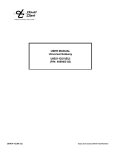
Overview
The U9920-GPB(EU) (40993G-02) Push Back Gateway is a portable wireless communication
device that when used in conjunction with one or more U9910-BSW(EU) (40992G-03) or U9912BSW(EU) Wireless Belt Stations provides communication for up to four users as well as an
interface to an aircraft intercom system. Only one gateway is required per system. Up to four
belt stations can be connected to one gateway.
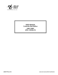
Hook
Lanyard
Rx Adjust
RE
M
T
R
E FLIGH
Power
Button
Link
Button
Status
LED
Banner
Model U9920-GPB(EU)
Push Back Gateway
P/N 40993G-02
Battery
Compartment
Battery Release
Screw
Figure 1: Overview of Gateway
2 of 9
19541P-71 (06-12)
Aircraft
Connector
Linking
Before a belt station and a gateway can be connected, they must first be linked. As a security
measure, the close-link feature requires devices to be in proximity of about 1 to 3 ft (0.3 to 0.9m)
in order to successfully link. This ensures that the units are not inadvertently linked with other
units on the premises.
Linking procedure:
1. Ensure power is on for both U9920-GPB(EU) and belt station (see Power-up/Powerdown)
2. Ensure units are within 1 to 3 ft (0.3 to 0.9m) of each other.
3. Simultaneously (within 1-2 sec) press and release the PTT button on the U9920-GPB(EU)
and the belt station to link with.
4. Amber LED’s will flash on both devices. A momentary red LED indicates a successful
close-link.
5. Upon successful link the U9920-GP(EU) will attempt to establish a connection with the
belt station.
6. Upon successfully establishing connection the LED on the gateway will flash a green
pattern corresponding to the number of belt stations connected.
Tip:
Once linked, the devices will not need to be linked again unless they are purged (see
Purging).
Each belt station is able to be linked to only one gateway at a time. A gateway can have up to six
belt stations linked and be connected to four of those six at one time.
Status Indications
The power button has a multi-color LED in the center which serves as a status indication for the
gateway. Table 1 below lists these states.
Table 1: LED Status Indications
LED Color
Red
Red
Red
Red
Orange
Orange
Orange
Green
Blink Rate
Solid
Once
Once
Any
Slow
Fast
Solid
Slow
3 of 9
19541P-71 (06-12)
Status
Initializing/power up
Connection Dropped
Connection Established
Low battery (approx. 1 hr remaining)
Idle/Disconnected
Link/Connection in Progress
PTT asserted
Connected (pattern indicates
number of belt stations connected)
Operation
Power-Up/Power-Down
To power up the U9920-GPB(EU) Push Back Gateway, press and hold the POWER button for
approximately two seconds. The LED will turn red and then begin flashing orange. If there are
linked belt stations within range, they will automatically connect to the gateway in a few seconds
after power up.
To power down the U9920-GPB(EU), press and hold the POWER button for approximately two
seconds. The LED will turn red and then turn off. The gateway is now powered down.
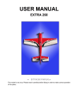
Aircraft Interface
•
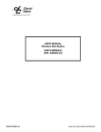
The U9920-GPB(EU) is designed for airport push back operations and can be connected to an
aircraft intercom system. Once connected, up to four belt station [U9910-BSW(EU)] users can
communicate to the pilot of the aircraft by pressing the PTT button on the belt station. A Push
Back Cable is required between the U9920-GPB(EU) and the aircraft (see below: Figure 2 –
connection illustration, and Table 2 – Push Back Cable matrix.)
Line up
Orange Dots and Twist
Figure 2: Push Back Cable Connection
Table 2: Push Back Gateway Interface Cable Matrix
Part Number
41035G-02
41035G-03
41035G-04
41035G-05
Configuration
PJ-051 Plug (1/4”)
U-174/U Plug (Civilian Only)
Dual G.A. Plugs (PJ-055/PJ-068)
U-174/U Plug (Military Only)
The included lanyard, hook, and Remove Before Flight banner (see Figure 1) facilitate the
temporary mounting of the U9920-GPB(EU) to an aircraft. The hook position on the lanyard is
adjustable to accommodate a variety of different mounting techniques. In addition, the belt clip
can be used to clip the gateway to an access door. Care and judgment should be exercised when
clipping or hooking to any part of the aircraft so that damage does not occur to the aircraft or the
gateway.
4 of 9
19541P-71 (06-12)
If possible, orient the gateway in such a way that it is as far away from any metal parts as
possible. This will increase the wireless range and robustness of communications.
WARNING:
ALWAYS REMOVE THE GATEWAY AND ALL ASSOCIATED ITEMS FROM THE AIRCRAFT
WHEN OPERATIONS ARE COMPLETE!
Aircraft Level Adjustment
Audio levels can vary between aircraft. To compensate for this, the U9920-GPB(EU) has a receive
level adjust knob (see Figure 1). Turning this knob will increase or decrease the audio level
coming from the aircraft and into the wireless intercom. By adjusting this knob, optimum
performance can be achieved.
Receive Level Adjustment Procedure
1. Connect at least one belt station to the U9920-GPB(EU) gateway and ensure sidetone
is present (see belt station User Manual).
2. Press and hold PTT
3. While holding PTT, begin speaking and slowly turn Receive Level Adjust knob on the
U9920-GPB(EU) gateway clockwise until you hear an echo of your own voice.
4. Turn the Receive Level Adjust knob slightly counter-clockwise until the echo stops.
5. Release PTT.
6. You may wish to verify communication with the pilot or someone hard-wired to the
aircraft’s intercom.
Communication
Note: It is highly recommended for wireless push-back systems that each headset user interface
through a non-VOX belt station [U9912-BSW(EU)], as extremely high and varying noise levels
within this environment can become challenging to the VOX feature, resulting in unwanted ramp
noise being present in a VOX belt station user's headset and causing him/her to frequently adjust
the VOX setting. VOX belt stations may be desired in more stable and less extreme noise
environments.
All connected belt stations will be able to communicate with each other through the U9920GPB(EU) while in range. Additionally, all belt station users will always hear any traffic on the
aircraft intercom. To speak over the aircraft intercom, the belt station user must press and hold
his/her PTT button. Multiple belt station users may PTT and thus speak over the aircraft intercom
simultaneously. Wireless intercom for all connected belt station users is also achieved in this
manner. For more information consult the user manual for the belt station.
5 of 9
19541P-71 (06-12)
Range
The range of a belt station and a gateway can be up to 300 ft (100m). If you are in an
environment with metal or concrete walls, this range could be reduced. If the belt station enters
into a "fringe" reception area, a brief sequence of three beeps will be heard in the headset. This
is to serve as a warning of a possible disconnection if conditions are not improved. When
possible, the user should attempt to regain line-of-sight contact with the controller. When the
belt station travels out of range of the gateway, a voice alert will indicate that the connection has
been lost. To reconnect, simply move back into range and connection with the gateway will
automatically be reestablished, also noted by a voice alert.
Low Battery
Under typical conditions, the battery in the gateway will last up to 24 hours or longer. The Status
LED turns red to indicate that the battery is running low. Additionally, a voice alert ("Gateway
Low Battery") is transmitted to all connected belt stations. This alert is not heard by the pilot of
the aircraft. At this point, approximately 1 hour of operation remains.
Auto Shut Off
The U9920-GPB(EU) will automatically shut off 30 minutes after the last belt station is
disconnected.
Purging
In some circumstances it may be necessary to “purge” the U9920-GPB(EU) of some of its linked
belt stations. Typically purging is not necessary unless there are multiple gateways in the same
vicinity and you wish to remove a belt station from this gateway and link to a different gateway.
A gateway can link up to six belt stations where a belt station can be linked to only one gateway
at a time.
Full Purge
A full purge is a purge method which clears all links in the gateway. After this procedure no belt
stations will automatically connect to this gateway until linked.
Full Purge procedure
1.
2.
3.
4.
5.
6.
Power down gateway (see Power-up/Power-down).
Press and hold PTT button. Do not release.
Power up the gateway (see Power-up/Power-down).
Release POWER button.
Release PTT button.
Status LED will flash red to indicate successful purge.
Smart Purge
A smart purge is a purge in which only unwanted links are removed from the gateway. When this
procedure is complete, only belt stations that are connected to the gateway remain linked. All
other belt station links will have been removed (see the belt station User Manual for the
individual belt station purging procedure when remaining link purging may be necessary.)
6 of 9
19541P-71 (06-12)
Smart Purge procedure
1. Ensure gateway is powered on and functioning.
2. Disconnect all belt stations to be purged (power off the belt stations).
3. Verify the number of green LED flashes on the gateway matches the number of
belt stations to be kept linked.
4. Press and hold LINK button on the gateway for 30 seconds until LED quickly
flashes red.
5. Release LINK button.
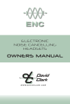
Battery Removal & Charging
All David Clark 9900-series wireless belt stations and battery operated controllers/gateways use a
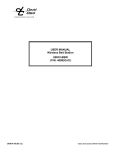
3.7V Li-Polymer rechargeable battery. This battery is removed by loosening the battery release
screw (See Figure 1). The batteries are charged with the A99-04CRG 4-bay battery charger
(41034G-01). When installing a battery, take care to align the battery properly and fully tighten
the screw (see Figure 3).
Lift Door
Insert Battery
with Contacts
Down
Figure 3: Battery Insertion/Removal
Troubleshooting
Table 2: Troubleshooting
Problem
Gateway will not turn on
Cannot link a belt station
Cannot speak to aircraft
Solution
Review Power-up/Power-down procedure
Ensure a fresh battery is installed
Review Registration procedure
Ensure units are within 1 to 3ft (0.3 to 0.9m) of
each other
Try a Full Purge
PTT not pressed
7 of 9
19541P-71 (06-12)
Replacement Parts
•
•
•
•
•
•
Battery (P/N: 40688G-90)
Protective skin, orange (A99-02SKN, P/N: 40796G-03)
Aircraft Interface Cord, PJ-051 {1/4" plug} (P/N: 41035G-02)
Aircraft Interface Cord, U-174/U plug {Civilian Only} (P/N: 41035G-03)
Aircraft Interface Cord, dual General Aviation plugs {Saab, others} (P/N: 41035G-04)
Aircraft Interface Cord, U-174/U Plug {Military Only} (P/N: 41035G-05)
Care and Maintenance
The U9920-GPB(EU) is not user serviceable. Do not attempt to open the enclosure. If this
product requires service, please contact the David Clark Co. Inc. Customer Service department:
•
Phone:
800.298.6235
•
E-Mail:
[email protected]
•
By Mail:
Customer Service
David Clark Company
360 Franklin Street
Worcester, MA 01604
If necessary, the U9920-GPB(EU) may be wiped down with a mild soap and water mixture.
Although it is a sealed device designed to withstand submersion in water to 1 meter, do not
unnecessarily submerse this product in water.
Avoid storage of this product in direct sunlight or high temperature environments.
Specifications
Frequency Range
Average RF Power Output
1880 MHz - 1900 MHz (EU)
10 mW (250 mW peak) (EU)
Range
300 ft (100m) line-of-sight (nominal)
Battery Life
24 hrs continuous use (nominal)
Operating Temperature
-14°F to 113°F (-10°C to +45°C)
Storage Temperature
-4°F to 140°F (-20°C to +60°C)
Power Requirements
3.7V @ 100mA nominal
Battery Type
3.7V 2000mAh Li-Polymer
8 of 9
19541P-71 (06-12)
Unauthorized Changes
Changes or modifications not expressly approved by David Clark Company, Inc. could void the
users’ authority to operate the equipment.
Usage Restrictions
Due to the DECT frequencies used, this product is licensed for operation only in the European
Union countries.
9 of 9
19541P-71 (06-12)