1
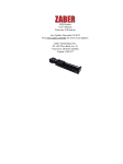
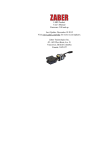
M-LSM Product
User's Manual
Firmware 5.00 and up
Last Update: December 10 2015
Visit www.zaber.com/wiki for more recent updates.
Zaber Technologies Inc.
#2 - 605 West Kent Ave. N.
Vancouver, British Columbia
Canada, V6P 6T7
Table of Contents
Disclaimer...........................................................................................................................................................1
General Description...........................................................................................................................................2
Installation..........................................................................................................................................................3
Mounting.................................................................................................................................................3
Installing a M-LSM with a flat base.......................................................................................................3
Installing a M-LSM to an Optical Post...................................................................................................3
Powering up an M-LSM.........................................................................................................................4
Operation............................................................................................................................................................6
Controller Connection.............................................................................................................................7
Pinout for D-sub 15 Connectors (A-series and X-Series controllers and peripherals)...........................7
Alternate Controllers...............................................................................................................................8
Warranty and Repair........................................................................................................................................9
Standard products....................................................................................................................................9
Custom products.....................................................................................................................................9
How to return products...........................................................................................................................9
Email Updates..................................................................................................................................................10
Contact Information........................................................................................................................................11
Appendix A: Default Settings.........................................................................................................................12
Appendix B: Device Specifications.................................................................................................................13
Appendix C: Device Drawings........................................................................................................................14
i
Disclaimer
Zaber’s devices are not intended for use in any critical medical, aviation, or military applications or situations
where a product's use or failure could cause personal injury, death, or damage to property. Zaber disclaims
any and all liability for injury or other damages resulting from the use of our products.
Disclaimer
1
General Description
Zaber's M-LSM series of Micromanipulators are used to position probes under a microscope with a joystick or
computer. They can be mounted to either metric or imperial optical breadboards. An adjustable probe holder
allows mounting of probe diameters between 2 and 13 mm. The controller connects to the RS-232 or USB
port of any computer.
General Description
2
Installation
Mounting
The M-LSM micromanipulator is specified either with a flat base or an adaptor plate to mount to an optical
post.
Installing a M-LSM with a flat base
•
Right hand M-LSM that mounts to a flat base. Ships assembled as shown above.
•
Bracket to mount to flat base shown for clarity, but remains assembled during installation.
•
Using either four M6 screws on a 50mm grid or 1/2" screws on a 2" grid attach M-LSM
micromanipulator to a flat base.
Installing a M-LSM to an Optical Post
Installation
3
•
Left hand post mounted M-LSM. Ships assembled as shown above, excluding the optical post.
•
Bracket to mount to an optical post for either a 1/2" or 12.7mm optical post.
•
Slide bracket over optical post into desired position and tighten M6 screw with 5 mm allen key to lock
M-LSM in position.
•
Ensure that the optical post doesn't extend too far, or it will interfere. The above image shows
incorrect installation where the optical post will obstruct the movement.
Powering up an M-LSM
•
Main components of M-LSM
Installing a M-LSM to an Optical Post
4
•
Cables required to connect the devices are labelled. Note: there are extra cables that are not required
during normal operation.
•
The X-MCB1 is connected to the X-MCB2 with a X-DC02 cable. Note: Power is only required to the
X-MCB1 or X-MCB2 since power is daisy chained to both the other controller and the joystick.
•
The X-JOY3 is connected to the X-MCB2 through the X-DC06 cable
Once the system has been installed, verify that each axis is working correctly by moving the joystick. Please
note that each stage needs to be homed before it is able to move the full length of travel. Homing the devices
is done by using the joystick to move each axis to the end of travel on the side of the motor.
Should you wish to mount alternative probes to the M-LSM custom adaptor plates are available upon request.
Please contact Zaber technical support at 1-888-276-8033 or [email protected] for more information.
Powering up an M-LSM
5
Operation
The joystick is pre-programmed with the following settings.
•
Default axes are setup with X as 1, Y as 2 and Z as 3
Key
Event 1
1
Event 2
Joystick Settings
Event 3
Stop
2
3
4
5
Set active axis 3 (Z)
Set Reference Position
Set Reference Position
Set Reference Position
Set Reference Position
Set active axis 1 Set axis velocity scale
6
(X)
3000
Set active axis 2 Set axis velocity scale
7
(Y)
3000
Set active axis 3 Set axis velocity scale
8
(Z)
3000
Button 8 reactivates the Z-axis.
Event 4
Set axis velocity scale 0
(Deactivate Z)
Go to Reference Position
Go to Reference Position
Go to Reference Position
Go to Reference Position
Set axis velocity scale
80000
Set axis velocity scale
80000
Set axis velocity scale
80000
•
Diagram of the event path for each key. The events are numbered from 1-4. This diagram shows what
events are issued depending on how long you hold the key.
Event 1
Event 2
Press
Quick release of button, less
button
than 2 seconds
Operation
Accessing key events
Event 3
Event 4
Hold button longer than 2 Release button after holding longer
seconds
than 2 seconds
6
The orange led will flash after about 2 seconds to signify that event 3 has been triggered.
If you would like to change the settings of the joystick refer to the X-JOY3 user manual.
Most of the information you will need to operate the stage using the X-MCB1 and X-MCB2 controller can be
found in the X-MCB1 user manual and here X-MCB2 user manual.
Controller Connection
The stages of the M-LSM series micromanipulators are controlled with X-MCB1 and X-MCB2 chopper drive
controllers. The stages used are LSM025A-M02T4 which have a peripheral ID of 43111 for each axis. If you
ever need to restore the correct settings for your M-LSM micromanipulator, verify that the peripheralid
settings for each axis are correct and send the /system restore↵ command to the X-MCB2 controller.
For reference, the pinout for the motor cable connectors is shown below:
Pinout for D-sub 15 Connectors (A-series and X-Series
controllers and peripherals)
A- or X-series controller (female)
T3 Peripheral (male)
T4 Peripheral (male)
Pin #
Function
1
+5V
2
Encoder Error ****
Controller Connection
7
3
reserved
4
Away Sensor ***
5
Home Sensor
6
Ground
7
Motor B1
8
Motor A1
9
+5V *
10
Encoder A *
11
Encoder B *
12
Encoder Index **
13
Ground *
14
Motor B2
15
Motor A2
* encoder embedded peripherals only
** devices with encoders with index only
*** devices with away sensors only
**** devices with linear or direct-reading encoders only
Alternate Controllers
The M-LSM may be controlled by any 2-phase stepper motor controller with limit sensor input. We do not
recommend using your own controller unless you are familiar with how to control a stepper motor with
hall sensor limit switches. Damage to the stage due to incorrect wiring is not covered by warranty.
Pinout for D-sub 15 Connectors (A-series and X-Seriescontrollers and peripherals)
8
Warranty and Repair
For Zaber's policies on warranty and repair, please refer to the Ordering Policies
Standard products
Standard products are any part numbers that do not contain the suffix ENG followed by a 4 digit number.
Most, but not all, standard products are listed for sale on our website. All standard Zaber products are backed
by a one-month satisfaction guarantee. If you are not satisfied with your purchase, we will refund your
payment minus any shipping charges. Goods must be in brand new saleable condition with no marks. Zaber
products are guaranteed for one year. During this period Zaber will repair any products with faults due to
manufacturing defects, free of charge.
Custom products
Custom products are any part numbers containing the suffix ENG followed by a 4 digit number. Each of these
products has been designed for a custom application for a particular customer. Custom products are
guaranteed for one year, unless explicitly stated otherwise. During this period Zaber will repair any products
with faults due to manufacturing defects, free of charge.
How to return products
Customers with devices in need of return or repair should contact Zaber to obtain an RMA form which must
be filled out and sent back to us to receive an RMA number. The RMA form contains instructions for packing
and returning the device. The specified RMA number must be included on the shipment to ensure timely
processing.
Warranty and Repair
9
Email Updates
If you would like to receive our periodic email newsletter including product updates and promotions, please
sign up online at www.zaber.com (news section). Newsletters typically include a promotional offer worth at
least $100.
Email Updates
10
Contact Information
Contact Zaber Technologies Inc by any of the following methods:
Phone 1-604-569-3780 (direct)
1-888-276-8033 (toll free in North America)
Fax 1-604-648-8033
Mail #2 - 605 West Kent Ave. N., Vancouver, British Columbia, Canada, V6P 6T7
Web www.zaber.com
Email Please visit our website for up to date email contact information.
The original instructions for this product are available at http://www.zaber.com/wiki/Manuals/M-LSM.
Contact Information
11
Appendix A: Default Settings
see our website
Appendix A: Default Settings
12
Appendix B: Device Specifications
For complete device specifications for the M-LSM micromanipulator, please see our website.
Appendix B: Device Specifications
13
Appendix C: Device Drawings
For complete drawings and CAD models of the M-LSM micromanipulator, please see our website
Appendix C: Device Drawings
14
Specification
Microstep Size (Default Resolution)
Recommended Controller
Travel Range
Accuracy (unidirectional)
Repeatability
Backlash
Maximum Speed
Minimum Speed
Speed Resolution
Encoder Type
Communication Interface
Communication Protocol
Guide Type
Vertical Runout
Horizontal Runout
Pitch
Roll
Yaw
Probe Diameter Range
Probe Angle Range
Linear Motion Per Motor Rev
Motor Steps Per Rev
Motor Type
Inductance
Motor Connection
Default Resolution
Mechanical Drive System
Limit or Home Sensing
Axes of Motion
Appendix C: Device Drawings
Value
0.047625 µm
X-MCB2 (24 V) and X-MCB1 (24 V)
25.4 mm
8 µm
< 1 µm
< 3 µm
14 mm/s
0.00022 mm/s
0.00022 mm/s
None
RS-232
Zaber Binary or Zaber ASCII
Needle roller bearing
< 8 µm
< 12 µm
0.02 degrees
0.005 degrees
0.02 degrees
2-13 mm
360 degrees
0.6096 mm
200
Stepper (2 phase)
1.7 mH/phase
D-sub 15
1/64 of a step
Precision lead screw
Magnetic hall sensor
3
Alternate Unit
1.000 "
0.000315 "
< 0.000039 "
< 0.000118 "
0.551 "/s
0.00001 "/s
0.00001 "/s
< 0.000315 "
< 0.000472 "
0.349 mrad
0.087 mrad
0.349 mrad
0.079 "
6.283 rad
0.024 "
15
Vacuum Compatible
Operating Temperature Range
Stage Parallelism
RoHS Compliant
CE Compliant
Weight
Joystick Control
Appendix C: Device Drawings
No
0 to 50 degrees C
< 25 µm
Yes
Yes
0.952 kg
Velocity Mode
< 0.000984 "
16